Page 2902 of 6020

Engine Mechanical – V6 Page 6A1–125
Page 6A1–125
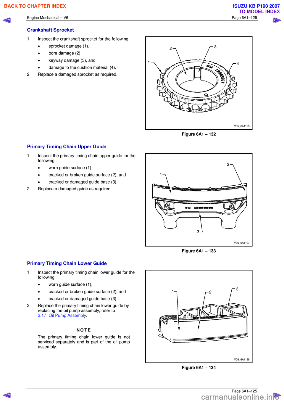
Crankshaft Sprocket
1 Inspect the crankshaft sprocket for the following:
• sprocket damage (1),
• bore damage (2),
• keyway damage (3), and
• damage to the cushion material (4).
2 Replace a damaged sprocket as required.
Figure 6A1 – 132
Primary Timing Chain Upper Guide
1 Inspect the primary timing chain upper guide for the following:
• worn guide surface (1),
• cracked or broken guide surface (2), and
• cracked or damaged guide base (3).
2 Replace a damaged guide as required.
Figure 6A1 – 133
Primary Timing Chain Lower Guide
1 Inspect the primary timing chain lower guide for the following:
• worn guide surface (1),
• cracked or broken guide surface (2), and
• cracked or damaged guide base (3).
2 Replace the primary timing chain lower guide by replacing the oil pump assembly, refer to
3.17 Oil Pump Assembly .
NOTE
The primary timing chain lower guide is not
serviced separately and is part of the oil pump
assembly.
Figure 6A1 – 134
BACK TO CHAPTER INDEX
TO MODEL INDEX
ISUZU KB P190 2007
Page 2908 of 6020
Engine Mechanical – V6 Page 6A1–131
Page 6A1–131
3 Install Tool No. EN 46105-1 (1) onto the rear of the
left-hand cylinder head camshafts (2), and Tool No.
EN 46105-2 onto the rear of the right-hand cylinder
head camshafts.
4 Ensure that Tool No. EN 46105 is fully seated onto the camshafts.
CAUTION
All camshafts must be locked in place before
installation of any timing chains.
Figure 6A1 – 147
5 Using Tool No. EN46111 (1), rotate the crankshaft in a clockwise direction until the crankshaft sprocket
timing mark (2) is aligned with the indexing mark (3)
on the oil pump housing.
Figure 6A1 – 148
6 Install the left-hand secondary timing chain (1) aligning the chain in the following manner:
Figure 6A1 – 149
BACK TO CHAPTER INDEX
TO MODEL INDEX
ISUZU KB P190 2007
Page 2917 of 6020
Engine Mechanical – V6 Page 6A1–140
Page 6A1–140
CAUTION
In order to install Tool No. EN 46105 onto the
camshafts, rotate the camshafts in an anti-
clockwise direction. There should be no
need to rotate the camshaft more than 45
degrees.
Figure 6A1 – 173
3 Install Tool No. EN 46105-1 (1) onto the rear of the
left-hand cylinder head camshafts (2).
CAUTION
All camshafts must be locked in place before
installation of any timing chains.
4 Ensure that Tool No. EN 46105 is fully seated onto the camshafts.
Figure 6A1 – 174
5 Using Tool No. EN46111 (1), rotate the crankshaft in a clockwise direction until the crankshaft sprocket
timing mark (2) is aligned with the indexing mark (3)
on the oil pump housing.
Figure 6A1 – 175
BACK TO CHAPTER INDEX
TO MODEL INDEX
ISUZU KB P190 2007
Page 2926 of 6020

Engine Mechanical – V6 Page 6A1–149
Page 6A1–149
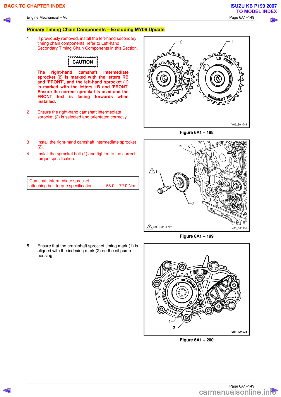
Primary Timing Chain Components – Excluding MY06 Update
1 If previously removed, install the left-hand secondary
timing chain components, refer to Left-hand
Secondary Timing Chain Components in this Section.
CAUTION
The right-hand camshaft intermediate
sprocket (2) is marked with the letters RB
and ‘FRONT’, and the left-hand sprocket (1)
is marked with the le tters LB and 'FRONT'
Ensure the correct sprocket is used and the
FRONT text is facing forwards when
installed.
2 Ensure the right-hand camshaft intermediate sprocket (2) is selected and orientated correctly.
Figure 6A1 – 198
3 Install the right-hand camshaft intermediate sprocket (2).
4 Install the sprocket bolt (1) and tighten to the correct torque specification.
Camshaft intermediate sprocket
attaching bolt torque spec ification ........... 58.0 – 72.0 Nm
Figure 6A1 – 199
5 Ensure that the crankshaft sprocket timing mark (1) is aligned with the indexing mark (2) on the oil pump
housing.
Figure 6A1 – 200
BACK TO CHAPTER INDEX
TO MODEL INDEX
ISUZU KB P190 2007
Page 2929 of 6020
Engine Mechanical – V6 Page 6A1–152
Page 6A1–152
NOTE
Do not remove the primary timing chain lower
guide (1). The primary timing chain lower guide
is not serviced separately. If the primary timing
chain lower guide must be replaced, the oil
pump assembly (2) must be replaced.
Figure 6A1 – 207
12 Ensure the primary timing chain upper guide is selected and orientated correctly.
Figure 6A1 – 208
13 Install the primary ti ming chain upper guide (1).
14 Install the primary timing chain upper guide bolts (2) and tighten to the correct torque specification.
Primary timing chain upper guide
attaching bolt torque spec ification ........... 20.0 – 26.0 Nm
Figure 6A1 – 209
BACK TO CHAPTER INDEX
TO MODEL INDEX
ISUZU KB P190 2007
Page 2934 of 6020
Engine Mechanical – V6 Page 6A1–157
Page 6A1–157
3 Install the right-hand camshaft intermediate
sprocket (2).
4 Install the sprocket bolt (1) and tighten to the correct torque specification.
Camshaft intermediate sprocket
attaching bolt torque spec ification ........... 58.0 – 72.0 Nm
Figure 6A1 – 220
5 Ensure that the crankshaft sprocket timing mark (1) is aligned with the indexing mark (2) on the oil pump
housing.
Figure 6A1 – 221
6 Install the primary timing chain (1).
Figure 6A1 – 222
BACK TO CHAPTER INDEX
TO MODEL INDEX
ISUZU KB P190 2007
Page 2937 of 6020
Engine Mechanical – V6 Page 6A1–160
Page 6A1–160
NOTE
Do not remove the primary timing chain lower
guide (1). The primary timing chain lower guide
is not serviced separately. If the primary timing
chain lower guide must be replaced, the oil
pump assembly (2) must be replaced.
Figure 6A1 – 228
12 Ensure the primary timing chain upper guide is selected and orientated correctly.
Figure 6A1 – 229
13 Install the primary ti ming chain upper guide (1).
14 Install the primary timing chain upper guide bolts (2) and tighten to the correct torque specification.
Primary timing chain upper guide
attaching bolt torque spec ification ........... 20.0 – 26.0 Nm
Figure 6A1 – 230
BACK TO CHAPTER INDEX
TO MODEL INDEX
ISUZU KB P190 2007
Page 2941 of 6020
Engine Mechanical – V6 Page 6A1–164
Page 6A1–164
Right-hand Secondary Timing Chain Components – Excluding MY06 Update
1 Install the primary timing chain components, refer to Primary Timing chain Components in this Section.
2 Using Tool No. EN46111 (1), rotate the crankshaft in a clockwise direction until the crankshaft sprocket
timing mark (2) is aligned with the indexing mark (3)
on the oil pump housing.
Figure 6A1 – 240
CAUTION
In order to install Tool No. EN 46105 onto the
camshafts, rotate the camshafts. There
should be no need to rotate the camshaft
more than 45 degrees.
Figure 6A1 – 241
3 Install Tool No. EN 46105–1 (1) onto the rear of the right-hand cylinder head camshafts (2).
Figure 6A1 – 242
BACK TO CHAPTER INDEX
TO MODEL INDEX
ISUZU KB P190 2007