Page 2878 of 6020

Engine Mechanical – V6 Page 6A1–101
Page 6A1–101
Clean and Inspect
1 Using a suitable non-corrosive cleaning solvent and a soft bristled parts cleaning brush, clean the crankshaft
balancer assembly.
Safety glasses must be worn when using
compressed air.
2 Dry the crankshaft balancer assembly using compressed air.
3 Inspect the crankshaft balancer assemb ly for the following fault conditions:
• Hub to crankshaft inner surface for wear or damage,
• Sealing surface for wear, grooving or scoring,
• Rubber ring between the hub and the pulley for wear, chunking and general deterioration, and
• Drive belt ribs of the pulley for damage.
Reinstall
CAUTION
Do not lubricate the crankshaft front oil seal
or crankshaft balancer sealing surfaces. The
crankshaft balancer must be installed onto a
dry seal.
1 Lubricate the crankshaft balancer assembly hub bore.
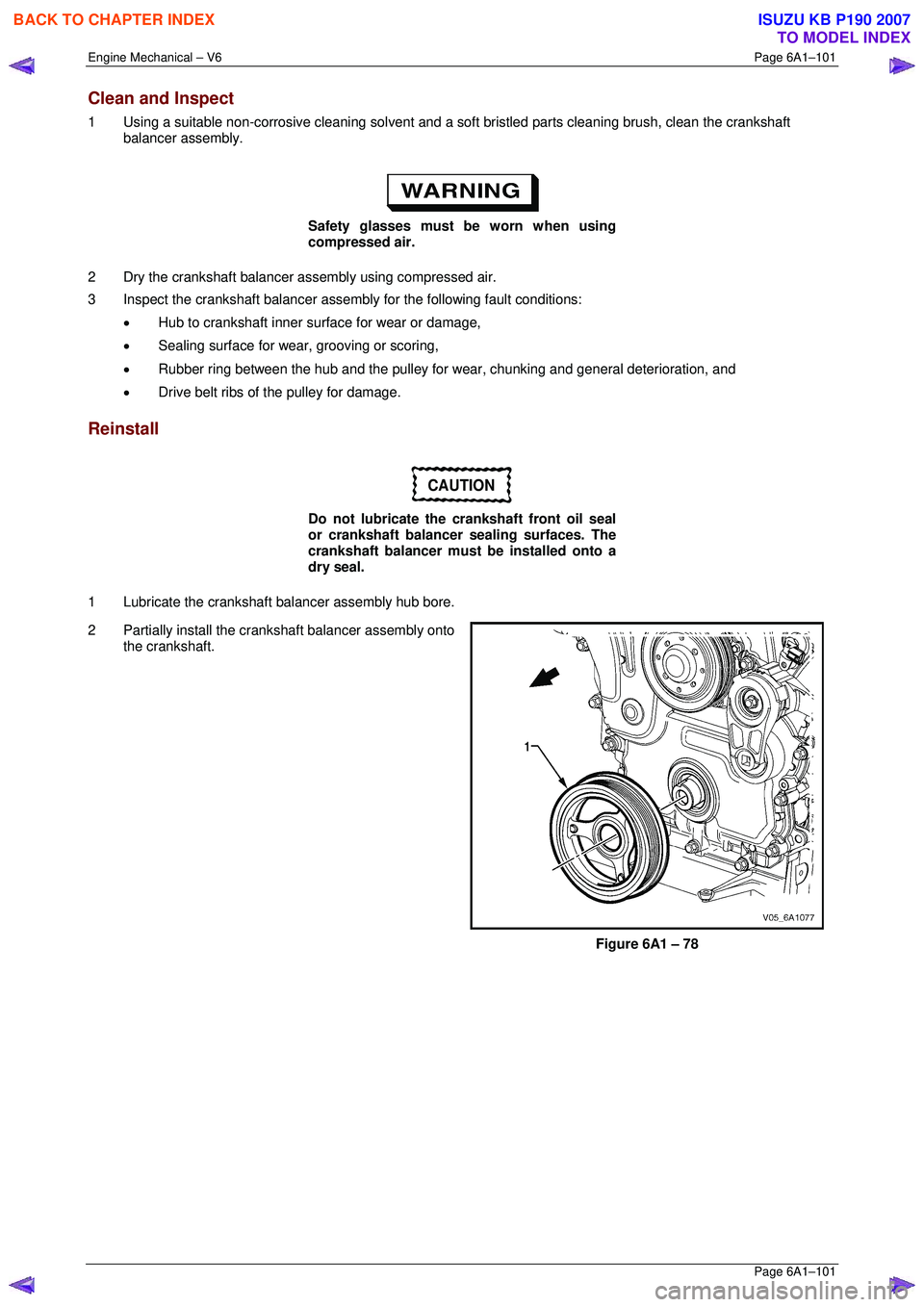
2 Partially install the crankshaft balancer assembly onto the crankshaft.
Figure 6A1 – 78
BACK TO CHAPTER INDEX
TO MODEL INDEX
ISUZU KB P190 2007
Page 2880 of 6020
Engine Mechanical – V6 Page 6A1–103
Page 6A1–103
3.14 Crankshaft Front Seal
Replace
1 Remove the crankshaft balancer assembly, refer to 3.13 Crankshaft Balancer Assembly .
2 Using a flat bladed tool (2) or seal remover, Tool No. E-308, carefully remove the crankshaft front seal (1)
from the front cover.
Figure 6A1 – 81
3 Using crankshaft front seal installer, Tool No. J-29184 (2) and a suitable hammer, install a new crankshaft
front seal (1) until fully s eated against the front cover
housing.
4 Install the crankshaft balanc er assembly, refer to
3.13 Crankshaft Balancer Assembly .
CAUTION
Do not lubricate the crankshaft front oil seal
or crankshaft balancer sealing surfaces. The
crankshaft balancer is installed into a dry
seal.
Figure 6A1 – 82
BACK TO CHAPTER INDEX
TO MODEL INDEX
ISUZU KB P190 2007
Page 2882 of 6020
Engine Mechanical – V6 Page 6A1–105
Page 6A1–105
11 Remove the front cover assembly (1).
Figure 6A1 – 85
Disassemble
1 Remove the crankshaft front oil seal (1) from the engine front cover (2) using a flat bladed tool or seal
remover, Tool No. E-308. Discard the seal.
Figure 6A1 – 86
2 Remove the camshaft position actuator valve oil seals (1) from the engine front cover (2). Discard the
seals.
Figure 6A1 – 87
BACK TO CHAPTER INDEX
TO MODEL INDEX
ISUZU KB P190 2007
Page 2883 of 6020
Engine Mechanical – V6 Page 6A1–106
Page 6A1–106
3 Remove the coolant pump seal (1) from the engine
front cover (2). Discard the seal.
Figure 6A1 – 88
Clean
4 Remove any RTV sealant (1) from the engine front cover using a plastic or wood scraper.
CAUTION
• Insert a piece of cardboard between the
front of the oil pan and oil pump to
prevent any contaminants from falling
into the oil pan.
• Do not use a sharp or metal gasket
scraper to clean the sealing surfaces.
5 Clean out any debris from the bolt holes.
6 Clean the front cover with a suitable cleaning solvent.
7 Dry the front cover with compressed air.
Safety glasses must be worn when using
compressed air.
Figure 6A1 – 89
8 Use compressed air to remove any engine coolant from the engine cooling passages and from the top of the oil
pan oil deflector.
BACK TO CHAPTER INDEX
TO MODEL INDEX
ISUZU KB P190 2007
Page 2884 of 6020

Engine Mechanical – V6 Page 6A1–107
Page 6A1–107
Inspect
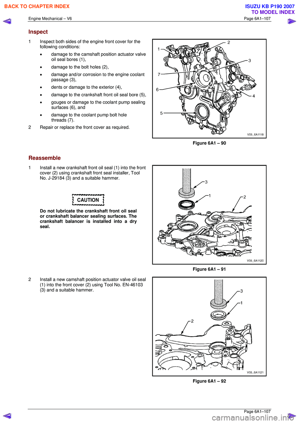
1 Inspect both sides of the engine front cover for the
following conditions:
• damage to the camshaft position actuator valve
oil seal bores (1),
• damage to the bolt holes (2),
• damage and/or corrosion to the engine coolant
passage (3),
• dents or damage to the exterior (4),
• damage to the crankshaft front oil seal bore (5),
• gouges or damage to the coolant pump sealing
surfaces (6), and
• damage to the coolant pump bolt hole
threads (7).
2 Repair or replace the fr ont cover as required.
Figure 6A1 – 90
Reassemble
1 Install a new crankshaft front oil seal (1) into the front cover (2) using crankshaft front seal installer, Tool
No. J-29184 (3) and a suitable hammer.
CAUTION
Do not lubricate the crankshaft front oil seal
or crankshaft balancer sealing surfaces. The
crankshaft balancer is installed into a dry
seal.
Figure 6A1 – 91
2 Install a new camshaft positi on actuator valve oil seal
(1) into the front cover (2) using Tool No. EN-46103
(3) and a suitable hammer.
Figure 6A1 – 92
BACK TO CHAPTER INDEX
TO MODEL INDEX
ISUZU KB P190 2007
Page 2886 of 6020
Engine Mechanical – V6 Page 6A1–109
Page 6A1–109
4 Place the front cover onto the special tools and slide
into position.
5 Remove the special tools from the cylinder block.
Figure 6A1 – 96
6 Hand start the front cover bolts (1).
Figure 6A1 – 97
7 Tighten the engine front cover bolts to the correct torque specification, in the sequence shown.
Engine front cover assembly attaching
bolt torque specificat ion .......................... 20.0 – 26.0 Nm
8 Fill the cooling system, refer to Section 6B1 Engine
Cooling – V6 .
9 Change the engine oil, refer to 3.1 Engine Oil.
Figure 6A1 – 98
BACK TO CHAPTER INDEX
TO MODEL INDEX
ISUZU KB P190 2007
Page 2891 of 6020
Engine Mechanical – V6 Page 6A1–114
Page 6A1–114
Remove
Right-hand Secondary Timing Chain
CAUTION
After removing the upper intake manifold, and
spark plugs, plug any openings to prevent dirt
and other contaminants from entering.
1 Remove the engine front cover assembly, refer to 3.15 Front Cover Assembly.
2 Remove the spark plugs to aid crankshaft/engine rotation, refer to Section 6C1-3 Engine Management – V6 –
Service Operations .
3 Install Tool No. EN46111 (1) onto the crankshaft (2).
Figure 6A1 – 103
4 Using Tool No. EN46111 (1), rotate the crankshaft in a clockwise direction until the crankshaft sprocket
timing mark (2) is aligned with the indexing mark (3)
on the oil pump housing.
NOTE
Graphic shows 'Early Type' crankshaft sprocket,
'Late Type' similar.
Figure 6A1 – 104
BACK TO CHAPTER INDEX
TO MODEL INDEX
ISUZU KB P190 2007
Page 2896 of 6020
Engine Mechanical – V6 Page 6A1–119
Page 6A1–119
NOTE
Do not remove the primary timing chain lower
guide (1). The primary timing chain lower guide
is not serviced separately. If the primary timing
chain lower guide requires replacement, the oil
pump assembly (2) must be replaced.
Figure 6A1 – 117
6 Remove the primary timing chain (1). NOTE
For ease of removal, remove the chain from the
crankshaft sprocket, bef ore attempting to
remove from the camshaft intermediate
sprockets.
Figure 6A1 – 118
7 If required, remove the right-hand camshaft intermediate sprocket bolt (1) and remove the
sprocket (2).
Figure 6A1 – 119
BACK TO CHAPTER INDEX
TO MODEL INDEX
ISUZU KB P190 2007