2007 INFINITI QX56 sensor
[x] Cancel search: sensorPage 2638 of 3061
SB-4
< SERVICE INFORMATION >
SEAT BELTS
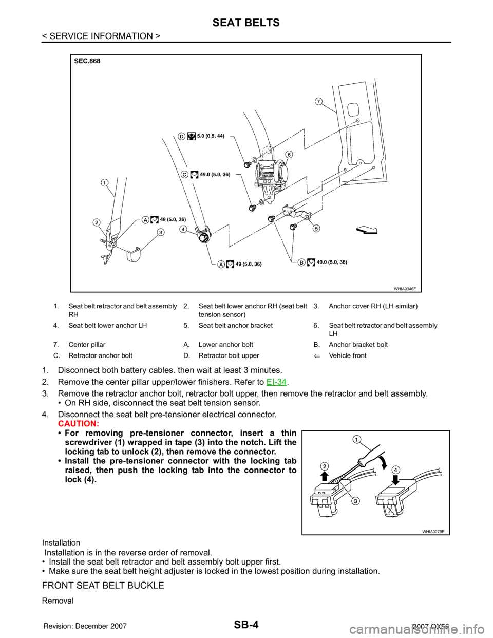
1. Disconnect both battery cables. then wait at least 3 minutes.
2. Remove the center pillar upper/lower finishers. Refer to EI-34
.
3. Remove the retractor anchor bolt, retractor bolt upper, then remove the retractor and belt assembly.
• On RH side, disconnect the seat belt tension sensor.
4. Disconnect the seat belt pre-tensioner electrical connector.
CAUTION:
• For removing pre-tensioner connector, insert a thin
screwdriver (1) wrapped in tape (3) into the notch. Lift the
locking tab to unlock (2), then remove the connector.
• Install the pre-tensioner connector with the locking tab
raised, then push the locking tab into the connector to
lock (4).
Installation
Installation is in the reverse order of removal.
• Install the seat belt retractor and belt assembly bolt upper first.
• Make sure the seat belt height adjuster is locked in the lowest position during installation.
FRONT SEAT BELT BUCKLE
Removal
1. Seat belt retractor and belt assembly
RH2. Seat belt lower anchor RH (seat belt
tension sensor)3. Anchor cover RH (LH similar)
4. Seat belt lower anchor LH 5. Seat belt anchor bracket 6. Seat belt retractor and belt assembly
LH
7. Center pillar A. Lower anchor bolt B. Anchor bracket bolt
C. Retractor anchor bolt D. Retractor bolt upper⇐Vehicle front
WHIA0346E
WHIA0279E
Page 2650 of 3061
SC-2
< SERVICE INFORMATION >
PRECAUTIONS
SERVICE INFORMATION
PRECAUTIONS
Precaution for Supplemental Restraint System (SRS) "AIR BAG" and "SEAT BELT
PRE-TENSIONER"
INFOID:0000000003533312
The Supplemental Restraint System such as “AIR BAG” and “SEAT BELT PRE-TENSIONER”, used along
with a front seat belt, helps to reduce the risk or severity of injury to the driver and front passenger for certain
types of collision. This system includes seat belt switch inputs and dual stage front air bag modules. The SRS
system uses the seat belt switches to determine the front air bag deployment, and may only deploy one front
air bag, depending on the severity of a collision and whether the front occupants are belted or unbelted.
Information necessary to service the system safely is included in the SRS and SB section of this Service Man-
ual.
WARNING:
• To avoid rendering the SRS inoperative, which could increase the risk of personal injury or death in
the event of a collision which would result in air bag inflation, all maintenance must be performed by
an authorized NISSAN/INFINITI dealer.
• Improper maintenance, including incorrect removal and installation of the SRS, can lead to personal
injury caused by unintentional activation of the system. For removal of Spiral Cable and Air Bag
Module, see the SRS section.
• Do not use electrical test equipment on any circuit related to the SRS unless instructed to in this
Service Manual. SRS wiring harnesses can be identified by yellow and/or orange harnesses or har-
ness connectors.
Precaution for Power Generation Variable Voltage Control SystemINFOID:0000000003533313
CAUTION:
For this model, the battery current sensor that is installed to the negative battery cable measures the
charging/discharging current of the battery and performs various engine controls. If an electrical com-
ponent is connected directly to the negative battery terminal, the current flowing through that compo-
nent will not be measured by the battery current sensor. This condition may cause a malfunction of
the engine control system and battery discharge may occur. Do not connect an electrical component
or ground wire directly to the battery terminal.
Page 2663 of 3061

CHARGING SYSTEM
SC-15
< SERVICE INFORMATION >
C
D
E
F
G
H
I
J
L
MA
B
SC
N
O
P
CHARGING SYSTEM
System DescriptionINFOID:0000000003533323
The generator provides DC voltage to operate the vehicle's electrical system and to keep the battery charged.
The voltage output is controlled by the IC regulator.
Power is supplied at all times to generator terminal 3 through
• 10A fuse (No. 30, located in the fuse and fusible link box).
Terminal 1 supplies power to charge the battery and operate the vehicle's electrical system. Output voltage is
controlled by the IC regulator at terminal 3 detecting the input voltage. A pulse width modulated (PWM) signal
is sent from terminal 37 of the IPDM E/R to terminal 4 of the generator. The ECM determines the duty cycle of
the power generation variable voltage control system. The charging circuit is protected by the 140A fusible link
[letter a, located in the fusible link box (battery)].
The generator is grounded through the engine.
With the ignition switch in the ON or START position, power is supplied
• through 10A fuse [No. 14, located in the fuse block (J/B)]
• to combination meter terminal 24 for the charge warning lamp.
Ground is supplied to terminal 13 of the combination meter through terminal 2 of the generator. With power
and ground supplied, the charge warning lamp will illuminate. When the generator is providing sufficient volt-
age with the engine running, the ground is opened and the charge warning lamp will go off. If the charge warn-
ing lamp illuminates with the engine running, a fault is indicated. The IC regulator warning function activates to
illuminate “CHARGE” warning lamp, if any of the following symptoms occur while generator is operating:
• Excessive voltage is produced.
• No voltage is produced.
POWER GENERATION VARIABLE VOLTAGE CONTROL SYSTEM
NOTE:
Power generation variable voltage control system has been adopted. By varying the voltage to the generator,
engine load due to power generation of the generator is reduced and fuel consumption is decreased.
Operation
• The battery current sensor detects the charging/discharging current of the battery. ECM judges the battery
condition based on this signal.
• ECM judges whether to control voltage according to the battery condition.
• ECM calculates the target power generation voltage according to the battery condition and sends the calcu-
lated value, through CAN lines, as the power generation command value to IPDM E/R.
• IPDM E/R converts the received power generation command value into the power generation command sig-
nal (PWM signal) and sends it to the IC regulator.
• The IC regulator performs final control over the power generation voltage.
• When there is no power generation command signal, the generator performs the normal power generation
according to the characteristic of the IC regulator.
NOTE:
When any malfunction is detected in the power generation variable voltage control system, power generation
is performed according to the characteristic of the IC regulator in the generator.
PKIB4908E
Page 2664 of 3061
SC-16
< SERVICE INFORMATION >
CHARGING SYSTEM
Component
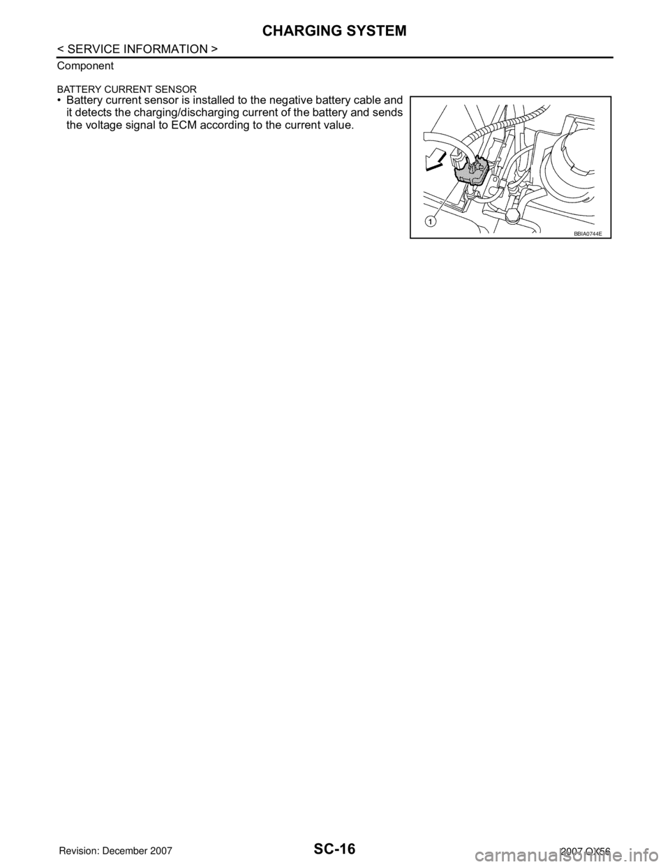
BATTERY CURRENT SENSOR
• Battery current sensor is installed to the negative battery cable and
it detects the charging/discharging current of the battery and sends
the voltage signal to ECM according to the current value.
BBIA0744E
Page 2666 of 3061
SC-18
< SERVICE INFORMATION >
CHARGING SYSTEM
Before starting, perform the preliminary inspection. Refer to "PRELIMINARY INSPECTION".
1. Stop the operation of the power generation variable voltage control system using either of the following
procedures.
• Using the CONSULT-II, select "ENGINE" from "SELECT SYSTEM" and set the "ALT DUTY" to 0%.
Keep "ALT DUTY" at 0% until the end of the inspection. When the "ALT DUTY" value is 0% or 100%,
normal power generation is performed according to the characteristic of the IC regulator in the genera-
tor.
• Turn the ignition switch off, and disconnect the battery current sensor connector. Disconnecting the bat-
tery current sensor may cause DTC (P1550 - P1554) to set. After finishing the inspection, connect the
battery current sensor connector and erase the self-diagnostic results history of the engine using CON-
SULT-II.
2. Turn off all loads on the vehicle electrical system.
3. Perform battery and starting system test with Battery/Starting/
Charging system tester.
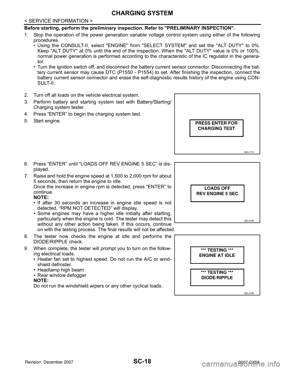
4. Press “ENTER” to begin the charging system test.
5. Start engine.
6. Press “ENTER” until “LOADS OFF REV ENGINE 5 SEC” is dis-
played.
7. Raise and hold the engine speed at 1,500 to 2,000 rpm for about
5 seconds, then return the engine to idle.
Once the increase in engine rpm is detected, press “ENTER” to
continue.
NOTE:
• If after 30 seconds an increase in engine idle speed is not
detected, “RPM NOT DETECTED” will display.
• Some engines may have a higher idle initially after starting,
particularly when the engine is cold. The tester may detect this
without any other action being taken. If this occurs, continue
on with the testing process. The final results will not be affected.
8. The tester now checks the engine at idle and performs the
DIODE/RIPPLE check.
9. When complete, the tester will prompt you to turn on the follow-
ing electrical loads.
• Heater fan set to highest speed. Do not run the A/C or wind-
shield defroster.
• Headlamp high beam
• Rear window defogger
NOTE:
Do not run the windshield wipers or any other cyclical loads.
SEL417X
SEL418X
SEL419X
Page 2673 of 3061
SE-1
BODY
C
D
E
F
G
H
J
K
L
M
SECTION SE
A
B
SE
N
O
P
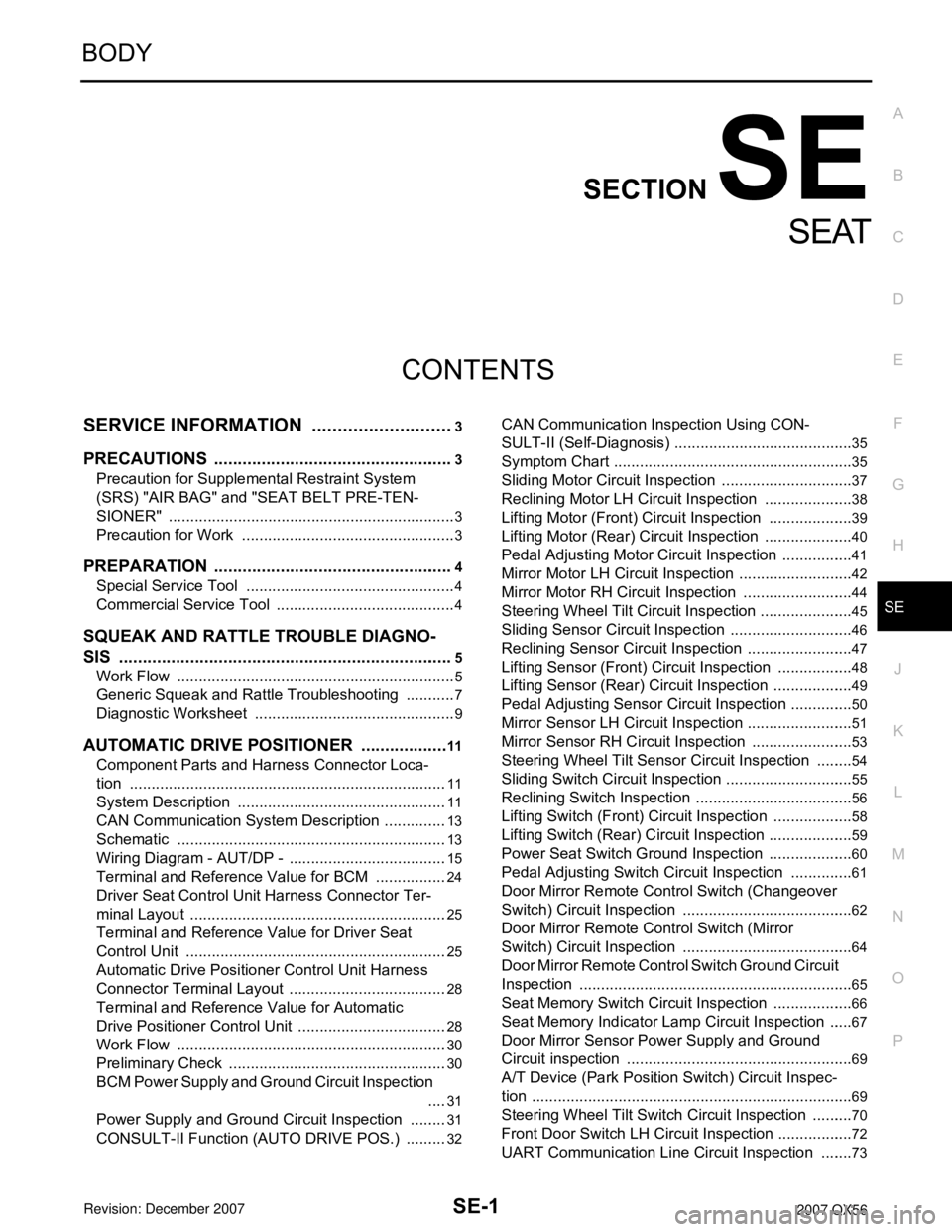
CONTENTS
SEAT
SERVICE INFORMATION ............................3
PRECAUTIONS ...................................................3
Precaution for Supplemental Restraint System
(SRS) "AIR BAG" and "SEAT BELT PRE-TEN-
SIONER" ...................................................................
3
Precaution for Work ..................................................3
PREPARATION ...................................................4
Special Service Tool .................................................4
Commercial Service Tool ..........................................4
SQUEAK AND RATTLE TROUBLE DIAGNO-
SIS .......................................................................
5
Work Flow .................................................................5
Generic Squeak and Rattle Troubleshooting ............7
Diagnostic Worksheet ...............................................9
AUTOMATIC DRIVE POSITIONER ...................11
Component Parts and Harness Connector Loca-
tion ..........................................................................
11
System Description .................................................11
CAN Communication System Description ...............13
Schematic ...............................................................13
Wiring Diagram - AUT/DP - .....................................15
Terminal and Reference Value for BCM .................24
Driver Seat Control Unit Harness Connector Ter-
minal Layout ............................................................
25
Terminal and Reference Value for Driver Seat
Control Unit .............................................................
25
Automatic Drive Positioner Control Unit Harness
Connector Terminal Layout .....................................
28
Terminal and Reference Value for Automatic
Drive Positioner Control Unit ...................................
28
Work Flow ...............................................................30
Preliminary Check ...................................................30
BCM Power Supply and Ground Circuit Inspection
....
31
Power Supply and Ground Circuit Inspection .........31
CONSULT-II Function (AUTO DRIVE POS.) ..........32
CAN Communication Inspection Using CON-
SULT-II (Self-Diagnosis) ..........................................
35
Symptom Chart ........................................................35
Sliding Motor Circuit Inspection ...............................37
Reclining Motor LH Circuit Inspection .....................38
Lifting Motor (Front) Circuit Inspection ....................39
Lifting Motor (Rear) Circuit Inspection .....................40
Pedal Adjusting Motor Circuit Inspection .................41
Mirror Motor LH Circuit Inspection ...........................42
Mirror Motor RH Circuit Inspection ..........................44
Steering Wheel Tilt Circuit Inspection ......................45
Sliding Sensor Circuit Inspection .............................46
Reclining Sensor Circuit Inspection .........................47
Lifting Sensor (Front) Circuit Inspection ..................48
Lifting Sensor (Rear) Circuit Inspection ...................49
Pedal Adjusting Sensor Circuit Inspection ...............50
Mirror Sensor LH Circuit Inspection .........................51
Mirror Sensor RH Circuit Inspection ........................53
Steering Wheel Tilt Sensor Circuit Inspection .........54
Sliding Switch Circuit Inspection ..............................55
Reclining Switch Inspection .....................................56
Lifting Switch (Front) Circuit Inspection ...................58
Lifting Switch (Rear) Circuit Inspection ....................59
Power Seat Switch Ground Inspection ....................60
Pedal Adjusting Switch Circuit Inspection ...............61
Door Mirror Remote Control Switch (Changeover
Switch) Circuit Inspection ........................................
62
Door Mirror Remote Control Switch (Mirror
Switch) Circuit Inspection ........................................
64
Door Mirror Remote Control Switch Ground Circuit
Inspection ................................................................
65
Seat Memory Switch Circuit Inspection ...................66
Seat Memory Indicator Lamp Circuit Inspection ......67
Door Mirror Sensor Power Supply and Ground
Circuit inspection .....................................................
69
A/T Device (Park Position Switch) Circuit Inspec-
tion ...........................................................................
69
Steering Wheel Tilt Switch Circuit Inspection ..........70
Front Door Switch LH Circuit Inspection ..................72
UART Communication Line Circuit Inspection ........73
Page 2697 of 3061
AUTOMATIC DRIVE POSITIONER
SE-25
< SERVICE INFORMATION >
C
D
E
F
G
H
J
K
L
MA
B
SE
N
O
P
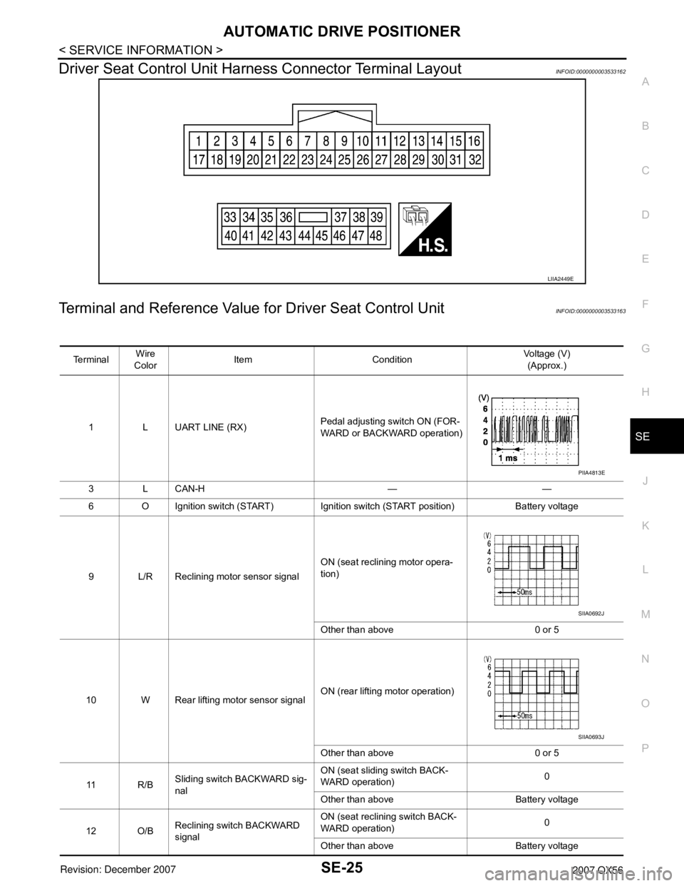
Driver Seat Control Unit Harness Connector Terminal LayoutINFOID:0000000003533162
Terminal and Reference Value for Driver Seat Control UnitINFOID:0000000003533163
LIIA2449E
Te r m i n a lWire
ColorItem ConditionVoltage (V)
(Approx.)
1 L UART LINE (RX)Pedal adjusting switch ON (FOR-
WARD or BACKWARD operation)
3 L CAN-H — —
6 O Ignition switch (START) Ignition switch (START position) Battery voltage
9 L/R Reclining motor sensor signalON (seat reclining motor opera-
tion)
Other than above 0 or 5
10 W Rear lifting motor sensor signalON (rear lifting motor operation)
Other than above 0 or 5
11 R / BSliding switch BACKWARD sig-
nalON (seat sliding switch BACK-
WARD operation)0
Other than above Battery voltage
12 O/BReclining switch BACKWARD
signalON (seat reclining switch BACK-
WARD operation)0
Other than above Battery voltage
PIIA4813E
SIIA0692J
SIIA0693J
Page 2698 of 3061
SE-26
< SERVICE INFORMATION >
AUTOMATIC DRIVE POSITIONER
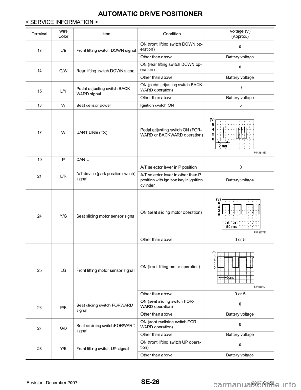
13 L/B Front lifting switch DOWN signalON (front lifting switch DOWN op-
eration)0
Other than above Battery voltage
14 G/W Rear lifting switch DOWN signalON (rear lifting switch DOWN op-
eration)0
Other than above Battery voltage
15 L/YPedal adjusting switch BACK-
WARD signalON (pedal adjusting switch BACK-
WARD operation) 0
Other than above Battery voltage
16 W Seat sensor power Ignition switch ON 5
17 W UART LINE (TX)Pedal adjusting switch ON (FOR-
WARD or BACKWARD operation)
19 P CAN-L — —
21 L/RA/T device (park position switch)
signalA/T selector lever in P position 0
A/T selector lever in other than P
position with ignition key in ignition
cylinderBattery voltage
24 Y/G Seat sliding motor sensor signalON (seat sliding motor operation)
Other than above 0 or 5
25 LG Front lifting motor sensor signalON (front lifting motor operation)
Other than above. 0 or 5
26 P/BSeat sliding switch FORWARD
signalON (seat sliding switch FOR-
WARD operation)0
Other than above Battery voltage
27 G/BSeat reclining switch FORWARD
signalON (seat reclining switch FOR-
WARD operation)0
Other than above Battery voltage
28 Y/B Front lifting switch UP signalON (front lifting switch UP opera-
tion)0
Other than above Battery voltage Te r m i n a lWire
ColorItem ConditionVoltage (V)
(Approx.)
PIIA4814E
PIIA3277E
SIIA0691J