2007 INFINITI QX56 sensor
[x] Cancel search: sensorPage 1941 of 3061
FL-10
< SERVICE INFORMATION >
FUEL TANK
FUEL TANK
Removal and InstallationINFOID:0000000003532207
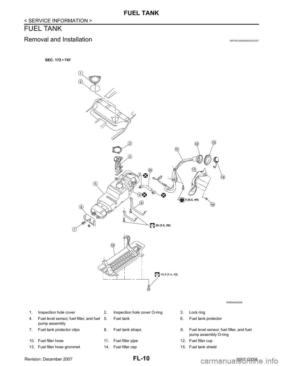
1. Inspection hole cover 2. Inspection hole cover O-ring 3. Lock ring
4. Fuel level sensor, fuel filter, and fuel
pump assembly5. Fuel tank 6. Fuel tank protector
7. Fuel tank protector clips 8. Fuel tank straps 9. Fuel level sensor, fuel filter, and fuel
pump assembly O-ring
10. Fuel filler hose 11. Fuel filler pipe 12. Fuel filler cup
13. Fuel filler hose grommet 14. Fuel filler cap 15. Fuel tank shield
AWBIA0522GB
Page 1943 of 3061
FL-12
< SERVICE INFORMATION >
FUEL TANK
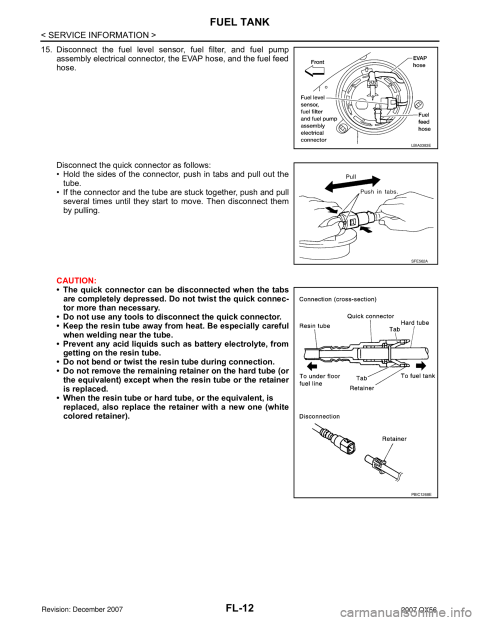
15. Disconnect the fuel level sensor, fuel filter, and fuel pump
assembly electrical connector, the EVAP hose, and the fuel feed
hose.
Disconnect the quick connector as follows:
• Hold the sides of the connector, push in tabs and pull out the
tube.
• If the connector and the tube are stuck together, push and pull
several times until they start to move. Then disconnect them
by pulling.
CAUTION:
• The quick connector can be disconnected when the tabs
are completely depressed. Do not twist the quick connec-
tor more than necessary.
• Do not use any tools to disconnect the quick connector.
• Keep the resin tube away from heat. Be especially careful
when welding near the tube.
• Prevent any acid liquids such as battery electrolyte, from
getting on the resin tube.
• Do not bend or twist the resin tube during connection.
• Do not remove the remaining retainer on the hard tube (or
the equivalent) except when the resin tube or the retainer
is replaced.
• When the resin tube or hard tube, or the equivalent, is
replaced, also replace the retainer with a new one (white
colored retainer).
LBIA0383E
SFE562A
PBIC1268E
Page 1944 of 3061
FUEL TANK
FL-13
< SERVICE INFORMATION >
C
D
E
F
G
H
I
J
K
L
MA
FL
N
P O
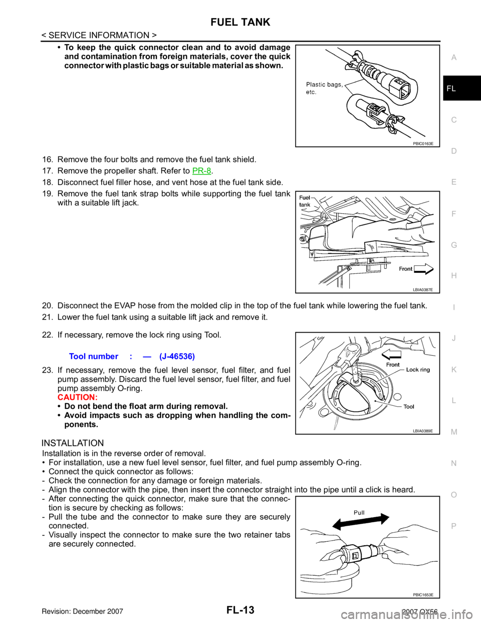
• To keep the quick connector clean and to avoid damage
and contamination from foreign materials, cover the quick
connector with plastic bags or suitable material as shown.
16. Remove the four bolts and remove the fuel tank shield.
17. Remove the propeller shaft. Refer to PR-8
.
18. Disconnect fuel filler hose, and vent hose at the fuel tank side.
19. Remove the fuel tank strap bolts while supporting the fuel tank
with a suitable lift jack.
20. Disconnect the EVAP hose from the molded clip in the top of the fuel tank while lowering the fuel tank.
21. Lower the fuel tank using a suitable lift jack and remove it.
22. If necessary, remove the lock ring using Tool.
23. If necessary, remove the fuel level sensor, fuel filter, and fuel
pump assembly. Discard the fuel level sensor, fuel filter, and fuel
pump assembly O-ring.
CAUTION:
• Do not bend the float arm during removal.
• Avoid impacts such as dropping when handling the com-
ponents.
INSTALLATION
Installation is in the reverse order of removal.
• For installation, use a new fuel level sensor, fuel filter, and fuel pump assembly O-ring.
• Connect the quick connector as follows:
- Check the connection for any damage or foreign materials.
- Align the connector with the pipe, then insert the connector straight into the pipe until a click is heard.
- After connecting the quick connector, make sure that the connec-
tion is secure by checking as follows:
- Pull the tube and the connector to make sure they are securely
connected.
- Visually inspect the connector to make sure the two retainer tabs
are securely connected.
PBIC0163E
LBIA0387E
Tool number : — (J-46536)
LBIA0389E
PBIC1653E
Page 1953 of 3061
ON-VEHICLE SERVICE
FSU-7
< SERVICE INFORMATION >
C
D
F
G
H
I
J
K
L
MA
B
FSU
N
O
P
• Check with the manufacturer of your specific alignment machine for their recommended Service/Cali-
bration Schedule.
THE ALIGNMENT PROCESS
IMPORTANT: Use only the alignment specifications listed in this Service Manual. Refer to FSU-19, "Wheel
Alignment (Unladen*1) *6".
1. When displaying the alignment settings, many alignment machines use “indicators”: (Green/red, plus or
minus, Go/No Go). Do NOT use these indicators.
• The alignment specifications programmed into your alignment machine that operate these indicators
may not be correct.
• This may result in an ERROR.
2. Some newer alignment machines are equipped with an optional “Rolling Compensation” method to “com-
pensate” the sensors (alignment targets or head units). Do NOT use this “Rolling Compensation”
method.
• Use the “Jacking Compensation” method. After installing the alignment targets or head units, raise the
vehicle and rotate the wheels 1/2 turn both ways.
• See Instructions in the alignment machine you are using for more information.
CAMBER AND CASTER
1. Measure camber and caster of both the right and left wheels
with a suitable alignment gauge and adjust as necessary to
specification.
NOTE:
Some vehicles may be equipped with straight (non-adjustable)
lower link bolts and washers. In order to adjust camber and
caster on these vehicles, first replace the lower link bolts and
washers with adjustable (cam) bolts and washers.
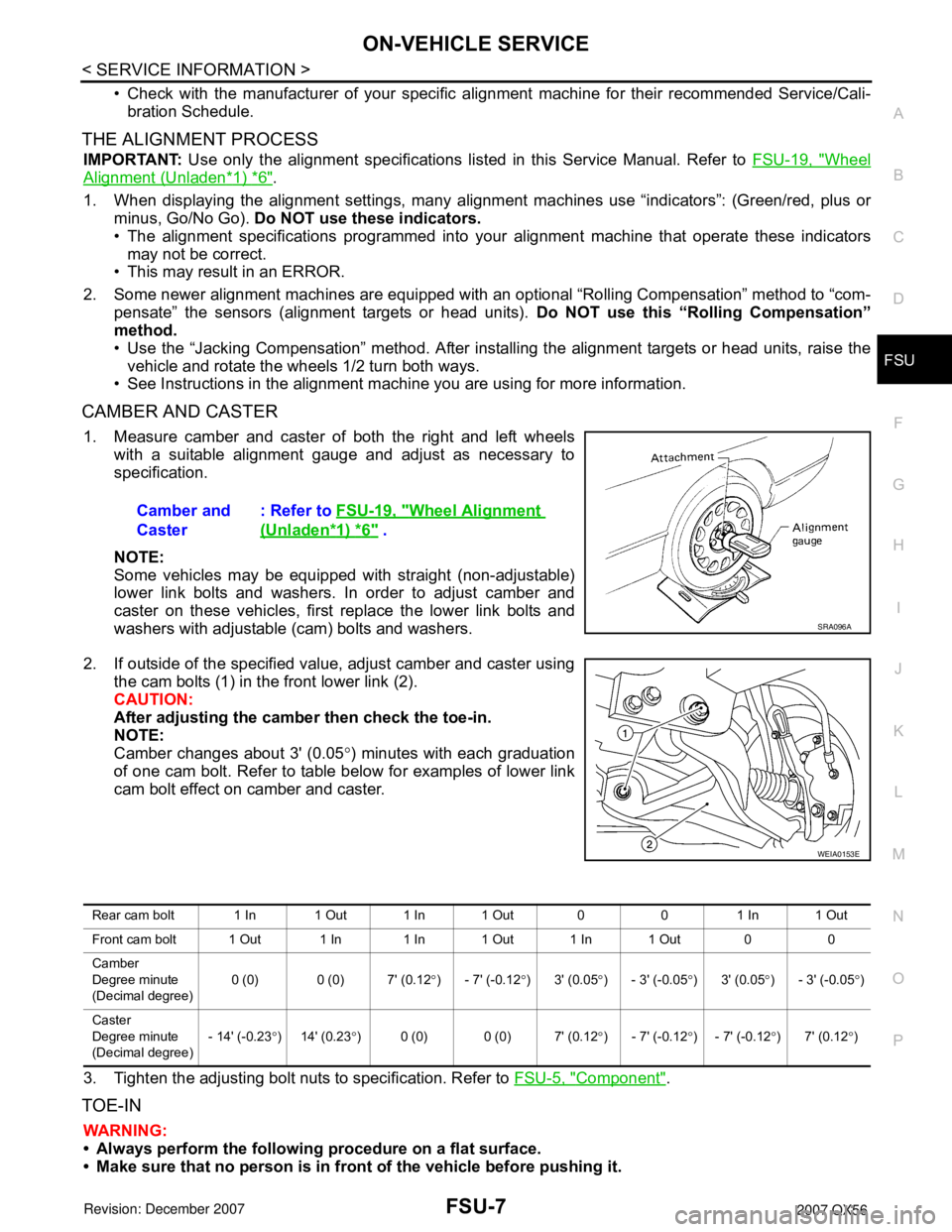
2. If outside of the specified value, adjust camber and caster using
the cam bolts (1) in the front lower link (2).
CAUTION:
After adjusting the camber then check the toe-in.
NOTE:
Camber changes about 3' (0.05°) minutes with each graduation
of one cam bolt. Refer to table below for examples of lower link
cam bolt effect on camber and caster.
3. Tighten the adjusting bolt nuts to specification. Refer to FSU-5, "
Component".
TOE-IN
WARNING:
• Always perform the following procedure on a flat surface.
• Make sure that no person is in front of the vehicle before pushing it.Camber and
Caster: Refer to FSU-19, "
Wheel Alignment
(Unladen*1) *6" .
SRA096A
WEIA0153E
Rear cam bolt 1 In 1 Out 1 In 1 Out 0 0 1 In 1 Out
Front cam bolt 1 Out 1 In 1 In 1 Out 1 In 1 Out 0 0
Camber
Degree minute
(Decimal degree)0 (0) 0 (0) 7' (0.12°) - 7' (-0.12°)3' (0.05°) - 3' (-0.05°)3' (0.05°) - 3' (-0.05°)
Caster
Degree minute
(Decimal degree)- 14' (-0.23°)14' (0.23°) 0 (0) 0 (0) 7' (0.12°) - 7' (-0.12°) - 7' (-0.12°)7' (0.12°)
Page 1963 of 3061
KNUCKLE
FSU-17
< SERVICE INFORMATION >
C
D
F
G
H
I
J
K
L
MA
B
FSU
N
O
P
KNUCKLE
On-Vehicle Inspection and ServiceINFOID:0000000003532645
Make sure the mounting conditions (looseness, backlash) of each component and component status (wear,
damage) are within specifications. Refer to FSU-20, "
Ball Joint" .
Removal and InstallationINFOID:0000000003532646
REMOVAL
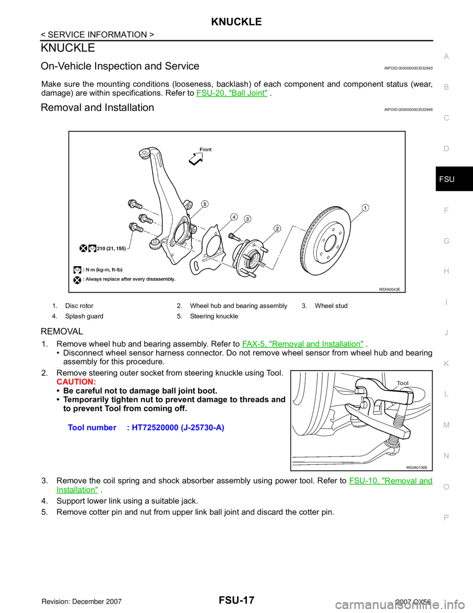
1. Remove wheel hub and bearing assembly. Refer to FAX-5, "Removal and Installation" .
• Disconnect wheel sensor harness connector. Do not remove wheel sensor from wheel hub and bearing
assembly for this procedure.
2. Remove steering outer socket from steering knuckle using Tool.
CAUTION:
• Be careful not to damage ball joint boot.
• Temporarily tighten nut to prevent damage to threads and
to prevent Tool from coming off.
3. Remove the coil spring and shock absorber assembly using power tool. Refer to FSU-10, "
Removal and
Installation" .
4. Support lower link using a suitable jack.
5. Remove cotter pin and nut from upper link ball joint and discard the cotter pin.
1. Disc rotor 2. Wheel hub and bearing assembly 3. Wheel stud
4. Splash guard 5. Steering knuckle
WDIA0043E
Tool number : HT72520000 (J-25730-A)
WGIA0130E
Page 1971 of 3061
PRECAUTIONS
GI-5
< SERVICE INFORMATION >
C
D
E
F
G
H
I
J
K
L
MB
GI
N
O
P
Precaution for Multiport Fuel Injection System or Engine Control SystemINFOID:0000000003531474
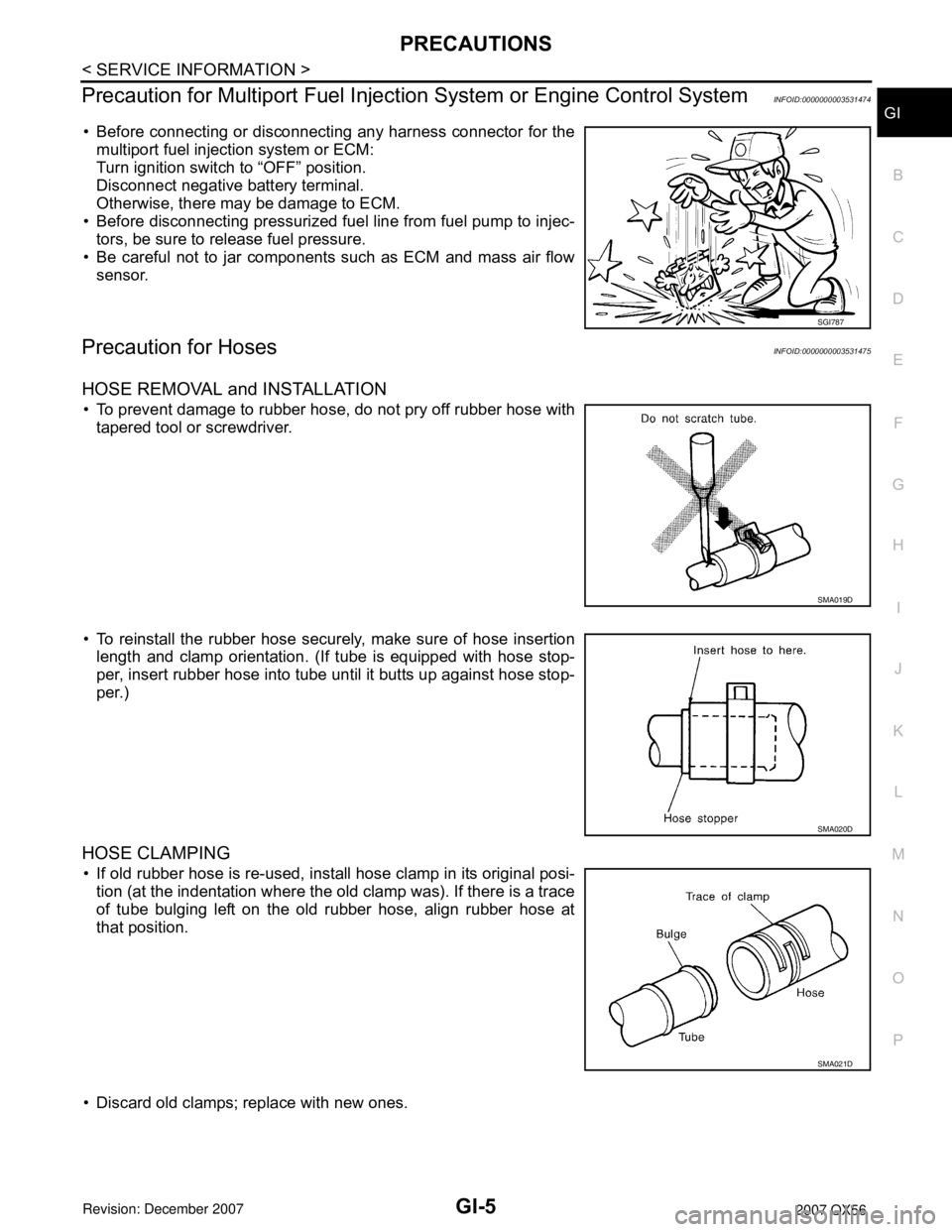
• Before connecting or disconnecting any harness connector for the
multiport fuel injection system or ECM:
Turn ignition switch to “OFF” position.
Disconnect negative battery terminal.
Otherwise, there may be damage to ECM.
• Before disconnecting pressurized fuel line from fuel pump to injec-
tors, be sure to release fuel pressure.
• Be careful not to jar components such as ECM and mass air flow
sensor.
Precaution for HosesINFOID:0000000003531475
HOSE REMOVAL and INSTALLATION
• To prevent damage to rubber hose, do not pry off rubber hose with
tapered tool or screwdriver.
• To reinstall the rubber hose securely, make sure of hose insertion
length and clamp orientation. (If tube is equipped with hose stop-
per, insert rubber hose into tube until it butts up against hose stop-
per.)
HOSE CLAMPING
• If old rubber hose is re-used, install hose clamp in its original posi-
tion (at the indentation where the old clamp was). If there is a trace
of tube bulging left on the old rubber hose, align rubber hose at
that position.
• Discard old clamps; replace with new ones.
SGI787
SMA019D
SMA020D
SMA021D
Page 1974 of 3061
GI-8
< SERVICE INFORMATION >
HOW TO USE THIS MANUAL
Contents
INFOID:0000000003531482
•ALPHABETICAL INDEX is provided at the end of this manual so that you can rapidly find the item and page
you are searching for.
•A QUICK REFERENCE INDEX, a black tab (e.g. ) is provided on the first page. You can quickly find the
first page of each section by matching it to the section's black tab.
•THE CONTENTS are listed on the first page of each section.
•THE TITLE is indicated on the upper portion of each page and shows the part or system.
•THE PAGE NUMBER of each section consists of two or three letters which designate the particular section
and a number (e.g. “BR-5”).
•THE SMALL ILLUSTRATIONS show the important steps such as inspection, use of special tools, knacks of
work and hidden or tricky steps which are not shown in the previous large illustrations.
Assembly, inspection and adjustment procedures for the complicated units such as the automatic transaxle
or transmission, etc. are presented in a step-by-step format where necessary.
ComponentINFOID:0000000003531483
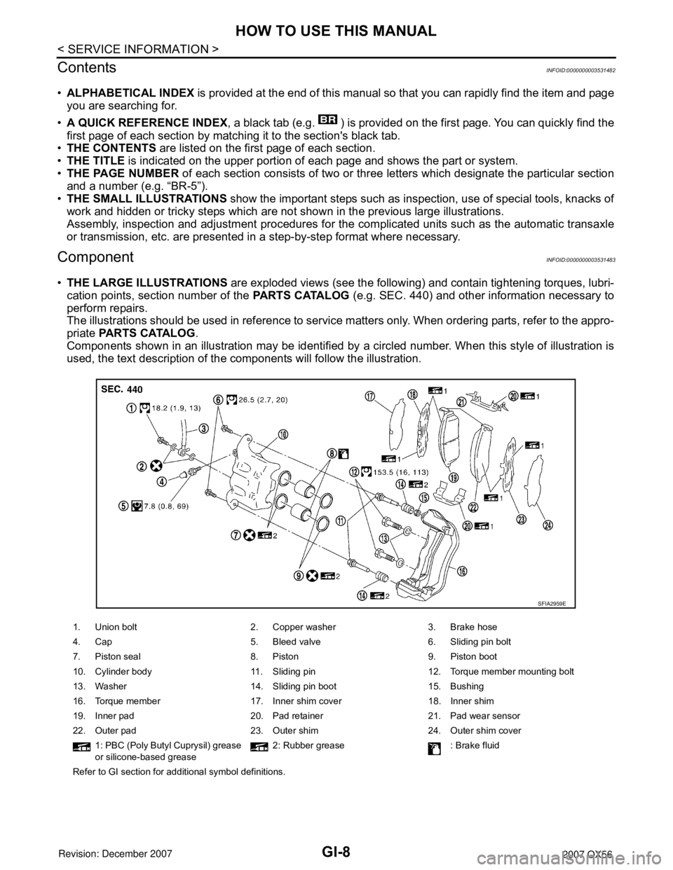
•THE LARGE ILLUSTRATIONS are exploded views (see the following) and contain tightening torques, lubri-
cation points, section number of the PARTS CATALOG (e.g. SEC. 440) and other information necessary to
perform repairs.
The illustrations should be used in reference to service matters only. When ordering parts, refer to the appro-
priate PARTS CATALOG.
Components shown in an illustration may be identified by a circled number. When this style of illustration is
used, the text description of the components will follow the illustration.
1. Union bolt 2. Copper washer 3. Brake hose
4. Cap 5. Bleed valve 6. Sliding pin bolt
7. Piston seal 8. Piston 9. Piston boot
10. Cylinder body 11. Sliding pin 12. Torque member mounting bolt
13. Washer 14. Sliding pin boot 15. Bushing
16. Torque member 17. Inner shim cover 18. Inner shim
19. Inner pad 20. Pad retainer 21. Pad wear sensor
22. Outer pad 23. Outer shim 24. Outer shim cover
1: PBC (Poly Butyl Cuprysil) grease
or silicone-based grease2: Rubber grease : Brake fluid
Refer to GI section for additional symbol definitions.
SFIA2959E
Page 1992 of 3061
GI-26
< SERVICE INFORMATION >
SERVICE INFORMATION FOR ELECTRICAL INCIDENT
• Cold or hot start up
Get a thorough description of the incident from the customer. It is important for simulating the conditions of the
problem.
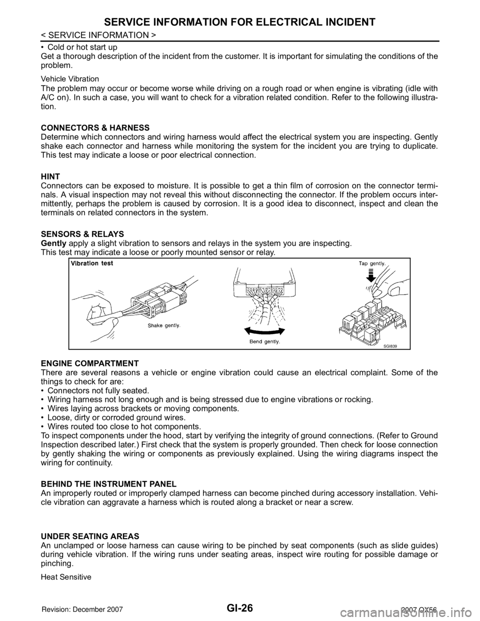
Vehicle Vibration
The problem may occur or become worse while driving on a rough road or when engine is vibrating (idle with
A/C on). In such a case, you will want to check for a vibration related condition. Refer to the following illustra-
tion.
CONNECTORS & HARNESS
Determine which connectors and wiring harness would affect the electrical system you are inspecting. Gently
shake each connector and harness while monitoring the system for the incident you are trying to duplicate.
This test may indicate a loose or poor electrical connection.
HINT
Connectors can be exposed to moisture. It is possible to get a thin film of corrosion on the connector termi-
nals. A visual inspection may not reveal this without disconnecting the connector. If the problem occurs inter-
mittently, perhaps the problem is caused by corrosion. It is a good idea to disconnect, inspect and clean the
terminals on related connectors in the system.
SENSORS & RELAYS
Gently apply a slight vibration to sensors and relays in the system you are inspecting.
This test may indicate a loose or poorly mounted sensor or relay.
ENGINE COMPARTMENT
There are several reasons a vehicle or engine vibration could cause an electrical complaint. Some of the
things to check for are:
• Connectors not fully seated.
• Wiring harness not long enough and is being stressed due to engine vibrations or rocking.
• Wires laying across brackets or moving components.
• Loose, dirty or corroded ground wires.
• Wires routed too close to hot components.
To inspect components under the hood, start by verifying the integrity of ground connections. (Refer to Ground
Inspection described later.) First check that the system is properly grounded. Then check for loose connection
by gently shaking the wiring or components as previously explained. Using the wiring diagrams inspect the
wiring for continuity.
BEHIND THE INSTRUMENT PANEL
An improperly routed or improperly clamped harness can become pinched during accessory installation. Vehi-
cle vibration can aggravate a harness which is routed along a bracket or near a screw.
UNDER SEATING AREAS
An unclamped or loose harness can cause wiring to be pinched by seat components (such as slide guides)
during vehicle vibration. If the wiring runs under seating areas, inspect wire routing for possible damage or
pinching.
Heat Sensitive
SGI839