Page 2669 of 3061

CHARGING SYSTEM
SC-21
< SERVICE INFORMATION >
C
D
E
F
G
H
I
J
L
MA
B
SC
N
O
P
NG >> Repair battery terminal connections.
2.CHECK FUSE AND FUSIBLE LINK
Check for blown fuses and fusible link.
OK or NG
OK >> GO TO 3.
NG >> If fuse is blown, be sure to eliminate cause of malfunction before installing new fuse.
3.CHECK GENERATOR DRIVE BELT TENSION
Check generator drive belt tension. Refer to EM-13, "
Checking Drive Belts".
OK or NG
OK >> Inspection End.
NG >> Repair as needed.
DIAGNOSTIC PROCEDURE 1
Check Charge Warning Lamp Circuit
1.CHECK CHARGE WARNING LAMP CIRCUIT CONNECTION
1. Turn the ignition switch OFF.
2. Check terminal 2 harness connector.
OK or NG
OK >> GO TO 2.
NG >> Repair terminal 2 connection. Confirm repair by performing complete Battery/Starting/Charging
system test. Refer to "Trouble Diagnoses with Battery/Starting/Charging System Tester" .
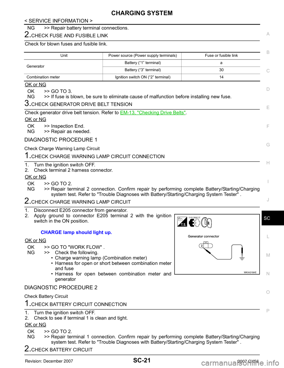
2.CHECK CHARGE WARNING LAMP CIRCUIT
1. Disconnect E205 connector from generator.
2. Apply ground to connector E205 terminal 2 with the ignition
switch in the ON position.
OK or NG
OK >> GO TO "WORK FLOW" .
NG >> Check the following.
• Charge warning lamp (Combination meter)
• Harness for open or short between combination meter
and fuse
• Harness for open between combination meter and
generator
DIAGNOSTIC PROCEDURE 2
Check Battery Circuit
1.CHECK BATTERY CIRCUIT CONNECTION
1. Turn the ignition switch OFF.
2. Check to see if terminal 1 is clean and tight.
OK or NG
OK >> GO TO 2.
NG >> Repair terminal 1 connection. Confirm repair by performing complete Battery/Starting/Charging
system test. Refer to "Trouble Diagnoses with Battery/Starting/Charging System Tester" .
2.CHECK BATTERY CIRCUIT
Unit Power source (Power supply terminals) Fuse or fusible link
GeneratorBattery (“1” terminal) a
Battery (“3” terminal) 30
Combination meter Ignition switch ON (“2” terminal) 14
CHARGE lamp should light up.
WKIA3184E
Page 2670 of 3061

SC-22
< SERVICE INFORMATION >
CHARGING SYSTEM
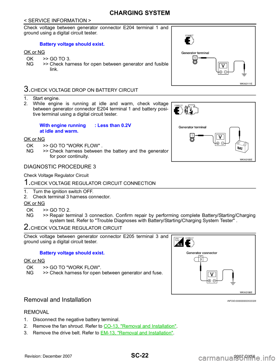
Check voltage between generator connector E204 terminal 1 and
ground using a digital circuit tester.
OK or NG
OK >> GO TO 3.
NG >> Check harness for open between generator and fusible
link.
3.CHECK VOLTAGE DROP ON BATTERY CIRCUIT
1. Start engine.
2. While engine is running at idle and warm, check voltage
between generator connector E204 terminal 1 and battery posi-
tive terminal using a digital circuit tester.
OK or NG
OK >> GO TO "WORK FLOW" .
NG >> Check harness between the battery and the generator
for poor continuity.
DIAGNOSTIC PROCEDURE 3
Check Voltage Regulator Circuit
1.CHECK VOLTAGE REGULATOR CIRCUIT CONNECTION
1. Turn the ignition switch OFF.
2. Check terminal 3 harness connector.
OK or NG
OK >> GO TO 2.
NG >> Repair terminal 3 connection. Confirm repair by performing complete Battery/Starting/Charging
system test. Refer to "Trouble Diagnoses with Battery/Starting/Charging System Tester" .
2.CHECK VOLTAGE REGULATOR CIRCUIT
Check voltage between generator connector E205 terminal 3 and
ground using a digital circuit tester.
OK or NG
OK >> GO TO "WORK FLOW".
NG >> Check harness for open between generator and fuse.
Removal and InstallationINFOID:0000000003533326
REMOVAL
1. Disconnect the negative battery terminal.
2. Remove the fan shroud. Refer to CO-13, "
Removal and Installation".
3. Remove the drive belt. Refer to EM-13, "
Removal and Installation". Battery voltage should exist.
WKIA2111E
With engine running
at idle and warm.: Less than 0.2V
WKIA3185E
Battery voltage should exist.
WKIA3186E
Page 2671 of 3061
CHARGING SYSTEM
SC-23
< SERVICE INFORMATION >
C
D
E
F
G
H
I
J
L
MA
B
SC
N
O
P
4. Remove the lower bracket, using power tools.
5. Remove the generator upper bolt, using power tools.
6. Remove/disconnect the generator harness connectors.
7. Remove the generator.
INSTALLATION
Installation is in the reverse order of removal.
• Install the generator and check the tension of the drive belt. Refer to EM-13, "
Checking Drive Belts".
CAUTION:
Tighten terminal nut carefully.
WKIA1390E
Terminal nut : 10.8 N·m (1.1 kg-m, 8 ft-lb)