2007 INFINITI QX56 charging
[x] Cancel search: chargingPage 532 of 3061

ATC-162
< SERVICE INFORMATION >
REFRIGERANT LINES
2. Remove the radiator. Refer to CO-13.
CAUTION:
Be careful not to damage the core su rface of the condenser and the radiator.
3. Disconnect the high-pressure flexible hose and the high-pressure pipe from the condenser.
CAUTION:
Cap or wrap the joint of the pipe with suitable ma terial such as vinyl tape to avoid the entry of air.
4. Disconnect the refrigerant pressure sensor connector. • Remove the refrigerant pressure sensor from the condenseras necessary.
5. Lift the condenser out of the mounting grommets to remove the condenser.
INSTALLATION
Installation is in the reverse order of removal.
Refer to ATC-152, "
Component".
CAUTION:
• Replace the O-rings of the high-p ressure pipe, refrigerant pressure sensor, and high-pressure flexi-
ble hose with new ones, then apply compr essor oil to them when installing them.
• After charging refrigerant, check for leaks.
• Replace the grommets as necessary.
LJIA0145E
Page 535 of 3061

REFRIGERANT LINESATC-165
< SERVICE INFORMATION >
C
DE
F
G H
I
K L
M A
B
AT C
N
O P
3. Remove the rear blower speed resistor.
4. Remove the rear air mix door motor.
5. Remove the rear duct and blend door assembly. Refer to AT C -
148, "Removal and Installation".
6. Disassemble the rear heater and cooling unit assembly to remove the evaporator.
INSTALLATION
Installation is in the reverse order of removal.
CAUTION:
• Replace the O-rings on the rear A/C pipes with ne w ones. Apply compressor oil to the O-rings when
installing them.
• After charging refrigerant, check for leaks.
Removal and Installation for Front Expansion ValveINFOID:0000000003533305
REMOVAL
1. Discharge the refrigerant. Refer to ATC-150, "HFC-134a (R-134a) Service Procedure".
2. Remove the front evaporator. Refer to ATC-163, "
Removal and Installation for Front Evaporator".
3. Remove the cooler grommet.
4. Remove the expansion valve.
INSTALLATION
Installation is in the reverse order of removal.
CAUTION:
• Replace the O-rings on the A/C re frigerant pipes with new ones, then apply compressor oil to them
when installing them.
• After charging refrigerant, check for leaks.
Removal and Installation for Rear Expansion ValveINFOID:0000000003533306
REMOVAL
1. Discharge the refrigerant. Refer to ATC-150, "HFC-134a (R-134a) Service Procedure".
2. Remove the luggage side lower finisher RH. Refer to EI-39
.
3. Disconnect the A/C refrigerant pi pes from the expansion valve.
CAUTION:
Cap or wrap the A/C refrigerant pipe ends with a suitable material such as vinyl tape to avoid the
entry of air and contaminants.
4. Remove the expansion valve.
LJIA0021E
WJIA0582E
Expansion valve bolts : 4 N·m (0.41 kg-m, 35 in-lb)
A/C refrigerant pipe to expansion valve bolt : Refer to ATC-152, "
Component".
Page 536 of 3061

ATC-166
< SERVICE INFORMATION >
REFRIGERANT LINES
INSTALLATION
Installation is in the reverse order of removal.
CAUTION:
• Replace the O-rings on the A/C refrigerant pipes with new ones, then apply compressor oil to them
when installing them.
• After charging refrigerant, check for leaks.
Checking of Refrigerant LeaksINFOID:0000000003533307
PRELIMINARY CHECK
Perform a visual inspection of all refrigeration parts, fittings, hoses and components for signs of A/C oil leak-
age, damage, and corrosion. Any A/C oil leakage may indi cate an area of refrigerant leakage. Allow extra
inspection time in these areas when using either an el ectronic refrigerant leak detector (J-41995) or fluores-
cent dye leak detector (J-42220).
If any dye is observed using a fluorescent dye leak detector (J-42220), confirm the leak using a electronic
refrigerant leak detector (J-41995). It is possible that the dye is from a prior leak that was repaired and not
properly cleaned.
When searching for leaks, do not stop when one leak is found but continue to check for additional leaks at all
system components and connections.
When searching for refrigerant leaks using an electronic refrigerant leak detector (J-41995), move the probe
along the suspected leak area at 25 - 50 mm (1 - 2 in) per second and no further than 6 mm (1/4 in) from the
component.
CAUTION:
Moving the electronic refrigerant l eak detector probe slower and clo ser to the suspected leak area will
improve the chances of finding a leak.
Checking System for L eaks Using the Fluoresc ent Dye Leak DetectorINFOID:0000000003533308
1. Check the A/C system for leaks using the fluorescent dye leak detector and safety goggles (J-42220) in a
low sunlight area (area without windows preferable). Il luminate all components, fittings and lines. The dye
will appear as a bright green/yellow area at the point of leakage. Fluorescent dye observed at the evapo-
rator drain opening indicates an evaporator core asse mbly leak (tubes, core or expansion valve).
2. If the suspected area is difficult to see, use an adjustable mirror or wipe the area with a clean shop rag or
cloth, then inspect the shop rag or cloth with the fl uorescent dye leak detector (J-42220) for dye residue.
3. After the leak is repaired, remove any residual dye using refrigerant dye cleaner (J-43872) to prevent
future misdiagnosis.
4. Perform a system performance check and then verify t he leak repair using a electronic refrigerant leak
detector (J-41995).
NOTE:
• Other gases in the work area or substances on the A/C components, for example, anti-freeze, wind-
shield washer fluid, solvents and oils, may falsely tri gger the leak detector. Make sure the surfaces to be
checked are clean.
• Clean with a dry cloth or blow off with shop air.
• Do not allow the sensor tip of the electronic refri gerant leak detector (J-41995) to contact with any sub-
stance. This can also cause false readings and may damage the detector.
Dye InjectionINFOID:0000000003533309
NOTE:
This procedure is only necessary when recharging the system or when the compressor has seized and must
be replaced.
1. Check the A/C system static (at rest) pressure . Pressure must be at least 345 kPa (3.52 kg/cm
2 , 50 psi).
2. Pour one bottle 7.4 cc (1/4 ounce) of the HFC-134a (R -134a) fluorescent leak detection dye (J-41447) into
the HFC-134a (R-134a) dye injector (J-41459).
CAUTION: Expansion valve bolts : 4 N·m (0.41 kg-m, 35 in-lb)
A/C refrigerant pipe to exp
ansion valve bolt : Refer to ATC-152, "
Component".
Page 1017 of 3061
![INFINITI QX56 2007 Factory Service Manual
DI-6
< SERVICE INFORMATION >
COMBINATION METERS
POWER SUPPLY AND GROUND CIRCUIT
Power is supplied at all times
• through 10A fuse [No.19, located in the fuse block (J/B)]
• to combination meter t INFINITI QX56 2007 Factory Service Manual
DI-6
< SERVICE INFORMATION >
COMBINATION METERS
POWER SUPPLY AND GROUND CIRCUIT
Power is supplied at all times
• through 10A fuse [No.19, located in the fuse block (J/B)]
• to combination meter t](/manual-img/42/57029/w960_57029-1016.png)
DI-6
< SERVICE INFORMATION >
COMBINATION METERS
POWER SUPPLY AND GROUND CIRCUIT
Power is supplied at all times
• through 10A fuse [No.19, located in the fuse block (J/B)]
• to combination meter terminal 8.
With the ignition switch in the ON or START position, power is supplied
• through 10A fuse [No.14, located in the fuse block (J/B)]
• to combination meter terminal 24.
Ground is supplied
• to combination meter terminal 17
• through body grounds M57, M61 and M79.
WATER TEMPERATURE GAUGE
The water temperature gauge indicates the engine coolant temperature.
ECM provides an engine coolant temperature signal to combination meter via CAN communication lines.
ENGINE OIL PRESSURE GAUGE
The engine oil pressure gauge indicates whether the engine oil pressure is low or normal.
The oil pressure gauge is controlled by the IPDM E/R (intelligent power distribution module engine room). Low
oil pressure causes oil pressure switch terminal 1 to provide ground to IPDM E/R terminal 42. The IPDM E/R
then signals the combination meter (unified meter control unit) via CAN communication lines and a low oil
pressure indication is displayed by the oil pressure gauge.
A/T OIL TEMPERATURE GAUGE
The A/T oil temperature gauge indicates the A/T fluid temperature.
TCM (transmission control module) provides an A/T flui d temperature signal to combination meter via CAN
communication lines.
VOLTAGE GAUGE
The voltage gauge indicates the battery/charging system voltage.
The voltage gauge is regulated by the unified meter control unit.
TA C H O M E T E R
The tachometer indicates engine speed in revolutions per minute (rpm).
ECM provides an engine speed signal to combination meter via CAN communication lines.
FUEL GAUGE
The fuel gauge indicates the approximate fuel level in the fuel tank.
The fuel gauge is regulated by the unified meter control unit and a variable resistor signal supplied
• to combination meter terminal 15.
• through fuel level sensor unit and fuel pump terminal 2
• through fuel level sensor unit and fuel pump terminal 5
• from combination meter terminal 16
SPEEDOMETER
ABS actuator and electric unit (contro l unit) provides a vehicle speed signal to the combination meter via CAN
communication lines.
ODO/TRIP METER
The vehicle speed signal and the memory signals from the meter memory circuit are processed by the combi-
nation meter and the mileage is displayed.
How to Change the Display
Refer to Owner's Manual for odo/tr ip meter operating instructions.
CAN COMMUNICATION SYSTEM DESCRIPTION
Refer to LAN-4.
Page 1566 of 3061

DTC P1550 BATTERY CURRENT SENSOR
EC-483
< SERVICE INFORMATION >
C
D
E
F
G
H
I
J
K
L
MA
EC
N
P O
DTC P1550 BATTERY CURRENT SENSOR
Component DescriptionINFOID:0000000003532011
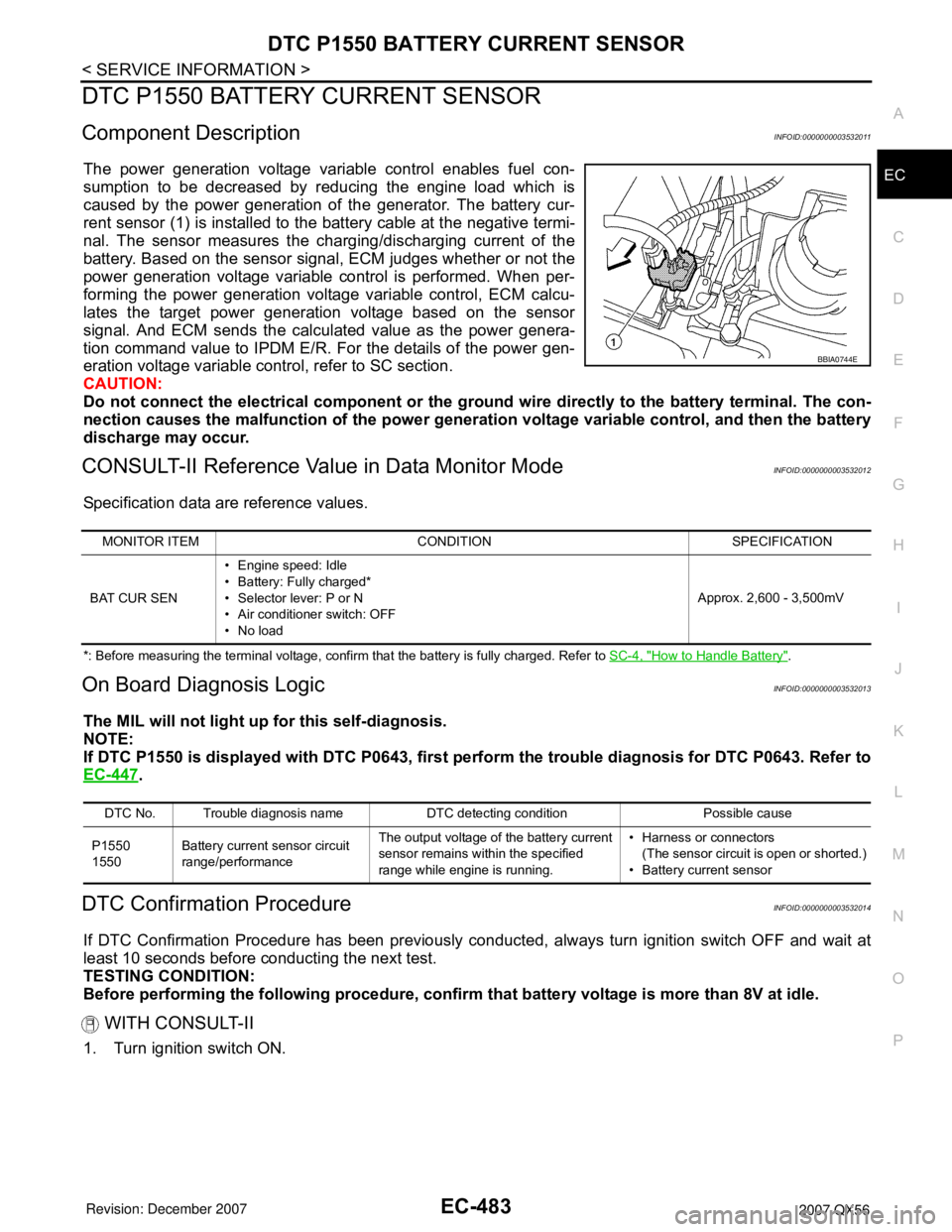
The power generation voltage variable control enables fuel con-
sumption to be decreased by reducing the engine load which is
caused by the power generation of the generator. The battery cur-
rent sensor (1) is installed to the battery cable at the negative termi-
nal. The sensor measures the charging/discharging current of the
battery. Based on the sensor signal, ECM judges whether or not the
power generation voltage variable control is performed. When per-
forming the power generation voltage variable control, ECM calcu-
lates the target power generation voltage based on the sensor
signal. And ECM sends the calculated value as the power genera-
tion command value to IPDM E/R. For the details of the power gen-
eration voltage variable control, refer to SC section.
CAUTION:
Do not connect the electrical component or the ground wire directly to the battery terminal. The con-
nection causes the malfunction of the power generation voltage variable control, and then the battery
discharge may occur.
CONSULT-II Reference Value in Data Monitor ModeINFOID:0000000003532012
Specification data are reference values.
*: Before measuring the terminal voltage, confirm that the battery is fully charged. Refer to SC-4, "How to Handle Battery".
On Board Diagnosis LogicINFOID:0000000003532013
The MIL will not light up for this self-diagnosis.
NOTE:
If DTC P1550 is displayed with DTC P0643, first perform the trouble diagnosis for DTC P0643. Refer to
EC-447
.
DTC Confirmation ProcedureINFOID:0000000003532014
If DTC Confirmation Procedure has been previously conducted, always turn ignition switch OFF and wait at
least 10 seconds before conducting the next test.
TESTING CONDITION:
Before performing the following procedure, confirm that battery voltage is more than 8V at idle.
WITH CONSULT-II
1. Turn ignition switch ON.
BBIA0744E
MONITOR ITEM CONDITION SPECIFICATION
BAT CUR SEN• Engine speed: Idle
• Battery: Fully charged*
• Selector lever: P or N
• Air conditioner switch: OFF
•No loadApprox. 2,600 - 3,500mV
DTC No. Trouble diagnosis name DTC detecting condition Possible cause
P1550
1550Battery current sensor circuit
range/performanceThe output voltage of the battery current
sensor remains within the specified
range while engine is running.• Harness or connectors
(The sensor circuit is open or shorted.)
• Battery current sensor
Page 1572 of 3061

DTC P1551, P1552 BATTERY CURRENT SENSOR
EC-489
< SERVICE INFORMATION >
C
D
E
F
G
H
I
J
K
L
MA
EC
N
P O
DTC P1551, P1552 BATTERY CURRENT SENSOR
Component DescriptionINFOID:0000000003532018
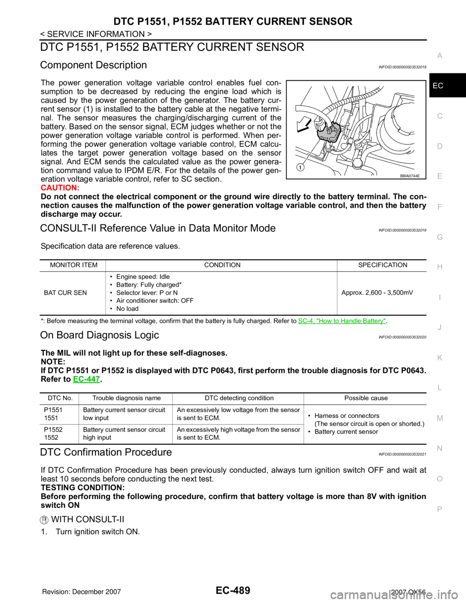
The power generation voltage variable control enables fuel con-
sumption to be decreased by reducing the engine load which is
caused by the power generation of the generator. The battery cur-
rent sensor (1) is installed to the battery cable at the negative termi-
nal. The sensor measures the charging/discharging current of the
battery. Based on the sensor signal, ECM judges whether or not the
power generation voltage variable control is performed. When per-
forming the power generation voltage variable control, ECM calcu-
lates the target power generation voltage based on the sensor
signal. And ECM sends the calculated value as the power genera-
tion command value to IPDM E/R. For the details of the power gen-
eration voltage variable control, refer to SC section.
CAUTION:
Do not connect the electrical component or the ground wire directly to the battery terminal. The con-
nection causes the malfunction of the power generation voltage variable control, and then the battery
discharge may occur.
CONSULT-II Reference Value in Data Monitor ModeINFOID:0000000003532019
Specification data are reference values.
*: Before measuring the terminal voltage, confirm that the battery is fully charged. Refer to SC-4, "How to Handle Battery".
On Board Diagnosis LogicINFOID:0000000003532020
The MIL will not light up for these self-diagnoses.
NOTE:
If DTC P1551 or P1552 is displayed with DTC P0643, first perform the trouble diagnosis for DTC P0643.
Refer to EC-447
.
DTC Confirmation ProcedureINFOID:0000000003532021
If DTC Confirmation Procedure has been previously conducted, always turn ignition switch OFF and wait at
least 10 seconds before conducting the next test.
TESTING CONDITION:
Before performing the following procedure, confirm that battery voltage is more than 8V with ignition
switch ON
WITH CONSULT-II
1. Turn ignition switch ON.
BBIA0744E
MONITOR ITEM CONDITION SPECIFICATION
BAT CUR SEN• Engine speed: Idle
• Battery: Fully charged*
• Selector lever: P or N
• Air conditioner switch: OFF
•No loadApprox. 2,600 - 3,500mV
DTC No. Trouble diagnosis name DTC detecting condition Possible cause
P1551
1551Battery current sensor circuit
low inputAn excessively low voltage from the sensor
is sent to ECM.• Harness or connectors
(The sensor circuit is open or shorted.)
• Battery current sensor P1552
1552Battery current sensor circuit
high inputAn excessively high voltage from the sensor
is sent to ECM.
Page 1578 of 3061

DTC P1553 BATTERY CURRENT SENSOR
EC-495
< SERVICE INFORMATION >
C
D
E
F
G
H
I
J
K
L
MA
EC
N
P O
DTC P1553 BATTERY CURRENT SENSOR
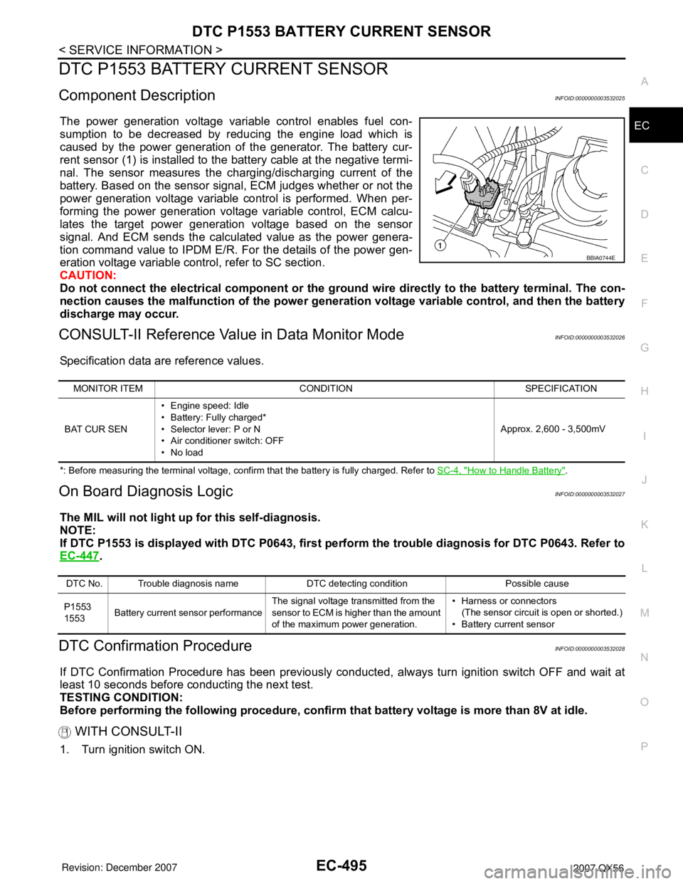
Component DescriptionINFOID:0000000003532025
The power generation voltage variable control enables fuel con-
sumption to be decreased by reducing the engine load which is
caused by the power generation of the generator. The battery cur-
rent sensor (1) is installed to the battery cable at the negative termi-
nal. The sensor measures the charging/discharging current of the
battery. Based on the sensor signal, ECM judges whether or not the
power generation voltage variable control is performed. When per-
forming the power generation voltage variable control, ECM calcu-
lates the target power generation voltage based on the sensor
signal. And ECM sends the calculated value as the power genera-
tion command value to IPDM E/R. For the details of the power gen-
eration voltage variable control, refer to SC section.
CAUTION:
Do not connect the electrical component or the ground wire directly to the battery terminal. The con-
nection causes the malfunction of the power generation voltage variable control, and then the battery
discharge may occur.
CONSULT-II Reference Value in Data Monitor ModeINFOID:0000000003532026
Specification data are reference values.
*: Before measuring the terminal voltage, confirm that the battery is fully charged. Refer to SC-4, "How to Handle Battery".
On Board Diagnosis LogicINFOID:0000000003532027
The MIL will not light up for this self-diagnosis.
NOTE:
If DTC P1553 is displayed with DTC P0643, first perform the trouble diagnosis for DTC P0643. Refer to
EC-447
.
DTC Confirmation ProcedureINFOID:0000000003532028
If DTC Confirmation Procedure has been previously conducted, always turn ignition switch OFF and wait at
least 10 seconds before conducting the next test.
TESTING CONDITION:
Before performing the following procedure, confirm that battery voltage is more than 8V at idle.
WITH CONSULT-II
1. Turn ignition switch ON.
BBIA0744E
MONITOR ITEM CONDITION SPECIFICATION
BAT CUR SEN• Engine speed: Idle
• Battery: Fully charged*
• Selector lever: P or N
• Air conditioner switch: OFF
•No loadApprox. 2,600 - 3,500mV
DTC No. Trouble diagnosis name DTC detecting condition Possible cause
P1553
1553Battery current sensor performanceThe signal voltage transmitted from the
sensor to ECM is higher than the amount
of the maximum power generation.• Harness or connectors
(The sensor circuit is open or shorted.)
• Battery current sensor
Page 1584 of 3061

DTC P1554 BATTERY CURRENT SENSOR
EC-501
< SERVICE INFORMATION >
C
D
E
F
G
H
I
J
K
L
MA
EC
N
P O
DTC P1554 BATTERY CURRENT SENSOR
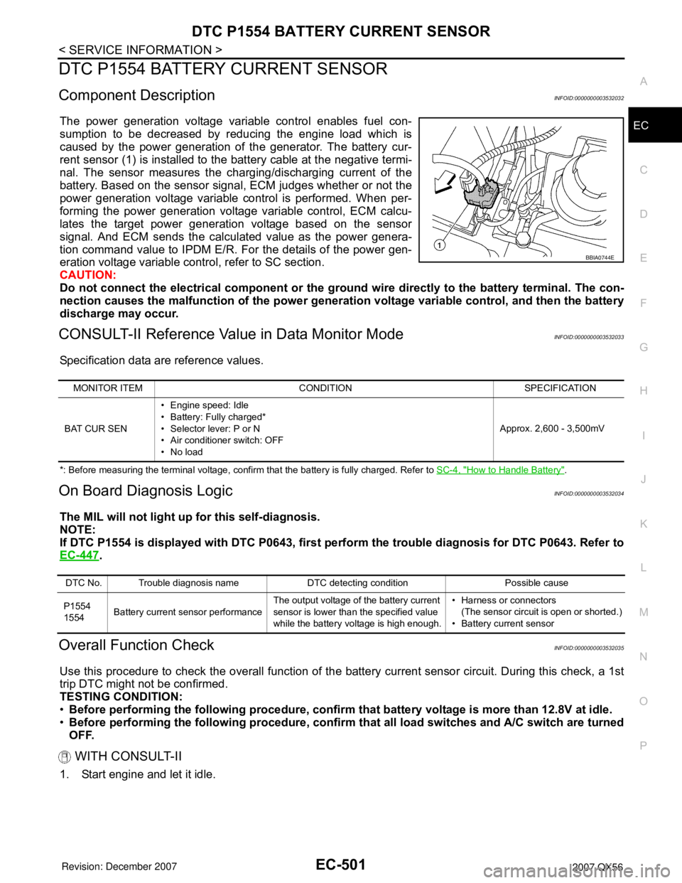
Component DescriptionINFOID:0000000003532032
The power generation voltage variable control enables fuel con-
sumption to be decreased by reducing the engine load which is
caused by the power generation of the generator. The battery cur-
rent sensor (1) is installed to the battery cable at the negative termi-
nal. The sensor measures the charging/discharging current of the
battery. Based on the sensor signal, ECM judges whether or not the
power generation voltage variable control is performed. When per-
forming the power generation voltage variable control, ECM calcu-
lates the target power generation voltage based on the sensor
signal. And ECM sends the calculated value as the power genera-
tion command value to IPDM E/R. For the details of the power gen-
eration voltage variable control, refer to SC section.
CAUTION:
Do not connect the electrical component or the ground wire directly to the battery terminal. The con-
nection causes the malfunction of the power generation voltage variable control, and then the battery
discharge may occur.
CONSULT-II Reference Value in Data Monitor ModeINFOID:0000000003532033
Specification data are reference values.
*: Before measuring the terminal voltage, confirm that the battery is fully charged. Refer to SC-4, "How to Handle Battery".
On Board Diagnosis LogicINFOID:0000000003532034
The MIL will not light up for this self-diagnosis.
NOTE:
If DTC P1554 is displayed with DTC P0643, first perform the trouble diagnosis for DTC P0643. Refer to
EC-447
.
Overall Function CheckINFOID:0000000003532035
Use this procedure to check the overall function of the battery current sensor circuit. During this check, a 1st
trip DTC might not be confirmed.
TESTING CONDITION:
•Before performing the following procedure, confirm that battery voltage is more than 12.8V at idle.
•Before performing the following procedure, confirm that all load switches and A/C switch are turned
OFF.
WITH CONSULT-II
1. Start engine and let it idle.
BBIA0744E
MONITOR ITEM CONDITION SPECIFICATION
BAT CUR SEN• Engine speed: Idle
• Battery: Fully charged*
• Selector lever: P or N
• Air conditioner switch: OFF
•No loadApprox. 2,600 - 3,500mV
DTC No. Trouble diagnosis name DTC detecting condition Possible cause
P1554
1554Battery current sensor performanceThe output voltage of the battery current
sensor is lower than the specified value
while the battery voltage is high enough.• Harness or connectors
(The sensor circuit is open or shorted.)
• Battery current sensor