2007 INFINITI QX56 display
[x] Cancel search: displayPage 2776 of 3061
SRS-6
< SERVICE INFORMATION >
SUPPLEMENTAL RESTRAINT SYSTEM (SRS)
Front Seat Belt Pre-tensioner with Load Limiter
INFOID:0000000003532858
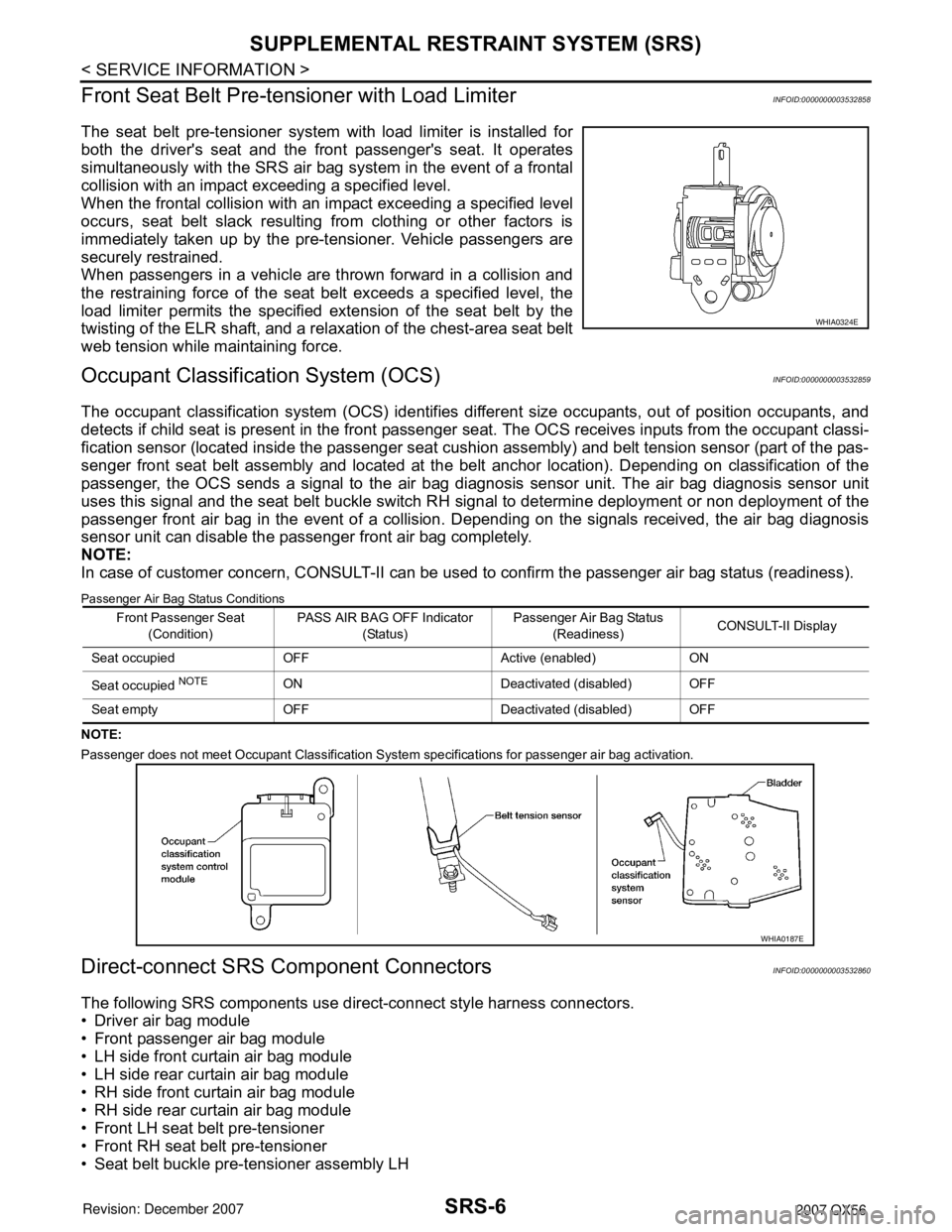
The seat belt pre-tensioner system with load limiter is installed for
both the driver's seat and the front passenger's seat. It operates
simultaneously with the SRS air bag system in the event of a frontal
collision with an impact exceeding a specified level.
When the frontal collision with an impact exceeding a specified level
occurs, seat belt slack resulting from clothing or other factors is
immediately taken up by the pre-tensioner. Vehicle passengers are
securely restrained.
When passengers in a vehicle are thrown forward in a collision and
the restraining force of the seat belt exceeds a specified level, the
load limiter permits the specified extension of the seat belt by the
twisting of the ELR shaft, and a relaxation of the chest-area seat belt
web tension while maintaining force.
Occupant Classification System (OCS)INFOID:0000000003532859
The occupant classification system (OCS) identifies different size occupants, out of position occupants, and
detects if child seat is present in the front passenger seat. The OCS receives inputs from the occupant classi-
fication sensor (located inside the passenger seat cushion assembly) and belt tension sensor (part of the pas-
senger front seat belt assembly and located at the belt anchor location). Depending on classification of the
passenger, the OCS sends a signal to the air bag diagnosis sensor unit. The air bag diagnosis sensor unit
uses this signal and the seat belt buckle switch RH signal to determine deployment or non deployment of the
passenger front air bag in the event of a collision. Depending on the signals received, the air bag diagnosis
sensor unit can disable the passenger front air bag completely.
NOTE:
In case of customer concern, CONSULT-II can be used to confirm the passenger air bag status (readiness).
Passenger Air Bag Status Conditions
NOTE:
Passenger does not meet Occupant Classification System specifications for passenger air bag activation.
Direct-connect SRS Component ConnectorsINFOID:0000000003532860
The following SRS components use direct-connect style harness connectors.
• Driver air bag module
• Front passenger air bag module
• LH side front curtain air bag module
• LH side rear curtain air bag module
• RH side front curtain air bag module
• RH side rear curtain air bag module
• Front LH seat belt pre-tensioner
• Front RH seat belt pre-tensioner
• Seat belt buckle pre-tensioner assembly LH
WHIA0324E
Front Passenger Seat
(Condition)PASS AIR BAG OFF Indicator
(Status)Passenger Air Bag Status
(Readiness)CONSULT-II Display
Seat occupied OFF Active (enabled) ON
Seat occupied
NOTEON Deactivated (disabled) OFF
Seat empty OFF Deactivated (disabled) OFF
WHIA0187E
Page 2778 of 3061

SRS-8
< SERVICE INFORMATION >
TROUBLE DIAGNOSIS
TROUBLE DIAGNOSIS
Trouble Diagnosis IntroductionINFOID:0000000003532861
CAUTION:
• Do not use electrical test equipment on any circuit related to the SRS unless instructed to do so in
this Service Manual. SRS wiring harnesses can be identified by yellow and/or orange harness con-
nectors.
• Do not attempt to repair, splice or modify SRS wiring harnesses. If a harness is damaged, replace it
with a new one.
• Keep ground connections clean.
DIAGNOSIS FUNCTION
The SRS self-diagnosis results can be read by using “AIR BAG” warning lamp and/or CONSULT-II.
The User mode is exclusively prepared for the customer (driver). This mode warns the driver of a system mal-
function through the operation of the “AIR BAG” warning lamp.
The Diagnosis mode allows the technician to locate and inspect the malfunctioning part.
The mode applications for the “AIR BAG” warning lamp and CONSULT-II are as follows:
HOW TO PERFORM TROUBLE DIAGNOSES FOR QUICK AND ACCURATE REPAIR
A good understanding of the malfunction conditions can make troubleshooting faster and more accurate.
In general, each customer feels differently about a malfunction. It is important to fully understand the symp-
toms or conditions for a customer complaint.
Information From Customer
WHAT - Vehicle model
WHEN - Date, Frequencies
WHERE - Road conditions
HOW - Operating conditions, Symptoms
Preliminary Check
Check that the following parts are in good order.
• Battery (Refer to SC-4, "
How to Handle Battery" .)
• Fuse (Refer to SRS-12, "
Wiring Diagram - SRS -" .)
• System component-to-harness connections
WORK FLOW
User mode Diagnosis mode Display type
“AIR BAG” warning lamp X X ON-OFF operation
CONSULT-II — X Monitoring
Page 2787 of 3061
TROUBLE DIAGNOSIS
SRS-17
< SERVICE INFORMATION >
C
D
E
F
G
I
J
K
L
MA
B
SRS
N
O
P
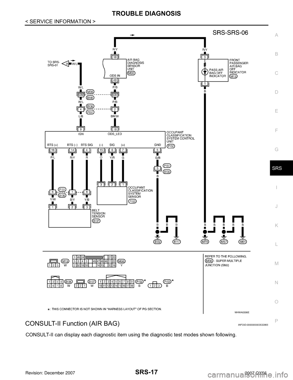
CONSULT-II Function (AIR BAG)INFOID:0000000003532865
CONSULT-II can display each diagnostic item using the diagnostic test modes shown following.
WHWA0306E
Page 2788 of 3061
SRS-18
< SERVICE INFORMATION >
TROUBLE DIAGNOSIS
CONSULT-II Function
INFOID:0000000003532866
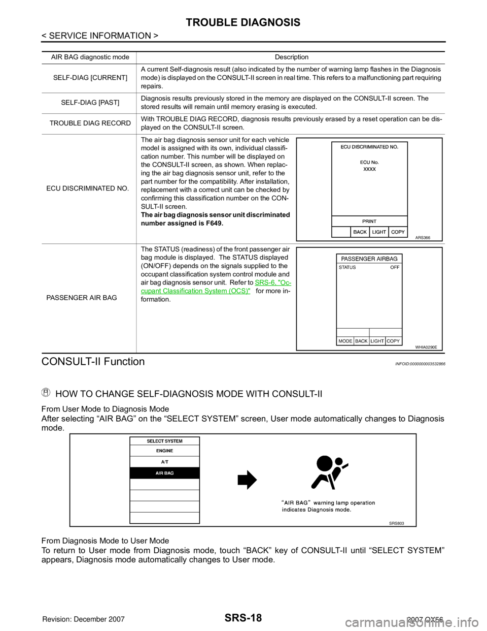
HOW TO CHANGE SELF-DIAGNOSIS MODE WITH CONSULT-II
From User Mode to Diagnosis Mode
After selecting “AIR BAG” on the “SELECT SYSTEM” screen, User mode automatically changes to Diagnosis
mode.
From Diagnosis Mode to User Mode
To return to User mode from Diagnosis mode, touch “BACK” key of CONSULT-II until “SELECT SYSTEM”
appears, Diagnosis mode automatically changes to User mode.
AIR BAG diagnostic mode Description
SELF-DIAG [CURRENT]A current Self-diagnosis result (also indicated by the number of warning lamp flashes in the Diagnosis
mode) is displayed on the CONSULT-II screen in real time. This refers to a malfunctioning part requiring
repairs.
SELF-DIAG [PAST]Diagnosis results previously stored in the memory are displayed on the CONSULT-II screen. The
stored results will remain until memory erasing is executed.
TROUBLE DIAG RECORDWith TROUBLE DIAG RECORD, diagnosis results previously erased by a reset operation can be dis-
played on the CONSULT-II screen.
ECU DISCRIMINATED NO.The air bag diagnosis sensor unit for each vehicle
model is assigned with its own, individual classifi-
cation number. This number will be displayed on
the CONSULT-II screen, as shown. When replac-
ing the air bag diagnosis sensor unit, refer to the
part number for the compatibility. After installation,
replacement with a correct unit can be checked by
confirming this classification number on the CON-
SULT-II screen.
The air bag diagnosis sensor unit discriminated
number assigned is F649.
PASSENGER AIR BAGThe STATUS (readiness) of the front passenger air
bag module is displayed. The STATUS displayed
(ON/OFF) depends on the signals supplied to the
occupant classification system control module and
air bag diagnosis sensor unit. Refer to SRS-6, "
Oc-
cupant Classification System (OCS)" for more in-
formation.
ARS366
WHIA0290E
SRS803
Page 2789 of 3061
![INFINITI QX56 2007 Factory Service Manual TROUBLE DIAGNOSIS
SRS-19
< SERVICE INFORMATION >
C
D
E
F
G
I
J
K
L
MA
B
SRS
N
O
P
HOW TO ERASE SELF-DIAGNOSIS RESULTS
• “SELF-DIAG [CURRENT]”
A current self-diagnosis result is displayed on the INFINITI QX56 2007 Factory Service Manual TROUBLE DIAGNOSIS
SRS-19
< SERVICE INFORMATION >
C
D
E
F
G
I
J
K
L
MA
B
SRS
N
O
P
HOW TO ERASE SELF-DIAGNOSIS RESULTS
• “SELF-DIAG [CURRENT]”
A current self-diagnosis result is displayed on the](/manual-img/42/57029/w960_57029-2788.png)
TROUBLE DIAGNOSIS
SRS-19
< SERVICE INFORMATION >
C
D
E
F
G
I
J
K
L
MA
B
SRS
N
O
P
HOW TO ERASE SELF-DIAGNOSIS RESULTS
• “SELF-DIAG [CURRENT]”
A current self-diagnosis result is displayed on the CONSULT-II
screen in real time.
After the malfunction is repaired completely, no malfunction is
detected on “SELF-DIAG [CURRENT]”.
• “SELF-DIAG [PAST]”
Return to the “SELF-DIAG [CURRENT]” CONSULT-II screen by
touching “BACK” key of CONSULT-II and select “SELF-DIAG
[PAST]” in SELECT DIAG MODE. Touch “ERASE” in “SELF-DIAG
[PAST]” mode.
NOTE:
If the memory of the malfunction in “SELF-DIAG [PAST]” is
not erased, the User mode will continue to show the system
malfunction by the operation of the warning lamp even if the
malfunction is repaired completely.
• “TROUBLE DIAG RECORD”
The memory of “TROUBLE DIAG RECORD” cannot be erased.
Self-Diagnosis Function (Without CONSULT-II)INFOID:0000000003532867
• The reading of these results is accomplished using one of two modes — “User mode” and “Diagnosis
mode”.
• After a malfunction is repaired, turn the ignition switch OFF for at least one second, then back ON. Diagnosis
mode returns to the User mode. At that time, the self-diagnostic result is cleared.
SRS804
SRS701
SRS702
Page 2792 of 3061
![INFINITI QX56 2007 Factory Service Manual SRS-22
< SERVICE INFORMATION >
TROUBLE DIAGNOSIS
Diagnostic code is displayed on "SELF-DIAG [CURRENT]".
If no malfunction is detected on "SELF-DIAG [CURRENT]", but mal-
function is detected in "SRS Op INFINITI QX56 2007 Factory Service Manual SRS-22
< SERVICE INFORMATION >
TROUBLE DIAGNOSIS
Diagnostic code is displayed on "SELF-DIAG [CURRENT]".
If no malfunction is detected on "SELF-DIAG [CURRENT]", but mal-
function is detected in "SRS Op](/manual-img/42/57029/w960_57029-2791.png)
SRS-22
< SERVICE INFORMATION >
TROUBLE DIAGNOSIS
Diagnostic code is displayed on "SELF-DIAG [CURRENT]".
If no malfunction is detected on "SELF-DIAG [CURRENT]", but mal-
function is detected in "SRS Operation Check", the following cases
may exist:
• "SELF-DIAG [PAST]" memory might not be erased.
• The SRS system malfunctions intermittently.
Refer to "DIAGNOSTIC PROCEDURE 4".
CONSULT-II Diagnostic Code Chart
WHIA0151E
SRS701
Diagnostic item ExplanationRepair order
Recheck SRS at each replacement
NO DTC IS DETECTEDMalfunction is indicat-
ed by the “AIR BAG”
warning lamp in User
mode.Low battery voltage (Less than 9V) 1. Go to SC-4
.
2. Go to "DIAGNOSTIC PROCE-
DURE 3" .
“SELF-DIAG [PAST]” memory might
not be erased.Go to "DIAGNOSTIC PROCEDURE 4"
.
Intermittent malfunction has been
detected in the past.Go to "DIAGNOSTIC PROCEDURE 5"
.
No malfunction is detected in User mode. —
DRIVER AIRBAG MODULE
[OPEN]
[B1049] or [B1054]Driver air bag module circuit is open (including the spiral ca-
ble).1. Visually check the wiring harness
connection.
2. Replace the harness if it has visi-
ble damage.
3. Replace driver air bag module.
4. Replace the spiral cable.
5. Replace the air bag diagnosis
sensor unit.
6. Replace the related harness. DRIVER AIRBAG MODULE
[VB-SHORT]
[B1050] or [B1055]Driver air bag module circuit is shorted to some power supply
circuit (including the spiral cable).
DRIVER AIRBAG MODULE
[GND-SHORT]
[B1051] or [B1056]Driver air bag module circuit is shorted to ground (including
the spiral cable).
DRIVER AIRBAG MODULE
[SHORT]
[B1052] or [B1057]Driver air bag module circuits are shorted to each other.
Page 2798 of 3061
SRS-28
< SERVICE INFORMATION >
TROUBLE DIAGNOSIS
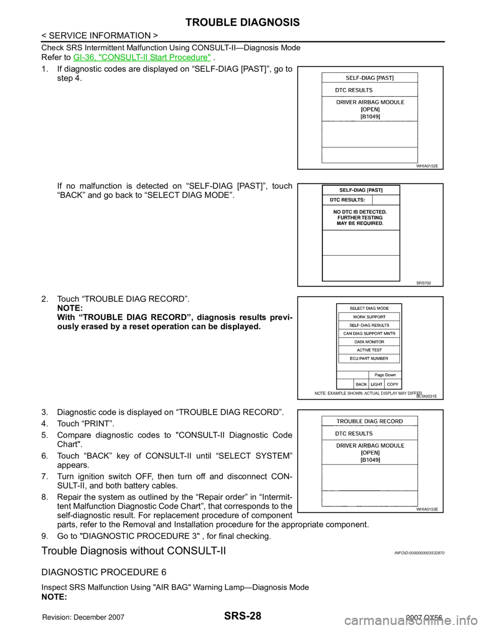
Check SRS Intermittent Malfunction Using CONSULT-II—Diagnosis Mode
Refer to GI-36, "CONSULT-II Start Procedure" .
1. If diagnostic codes are displayed on “SELF-DIAG [PAST]”, go to
step 4.
If no malfunction is detected on “SELF-DIAG [PAST]”, touch
“BACK” and go back to “SELECT DIAG MODE”.
2. Touch “TROUBLE DIAG RECORD”.
NOTE:
With “TROUBLE DIAG RECORD”, diagnosis results previ-
ously erased by a reset operation can be displayed.
3. Diagnostic code is displayed on “TROUBLE DIAG RECORD”.
4. Touch “PRINT”.
5. Compare diagnostic codes to "CONSULT-II Diagnostic Code
Chart".
6. Touch “BACK” key of CONSULT-II until “SELECT SYSTEM”
appears.
7. Turn ignition switch OFF, then turn off and disconnect CON-
SULT-II, and both battery cables.
8. Repair the system as outlined by the “Repair order” in “Intermit-
tent Malfunction Diagnostic Code Chart”, that corresponds to the
self-diagnostic result. For replacement procedure of component
parts, refer to the Removal and Installation procedure for the appropriate component.
9. Go to "DIAGNOSTIC PROCEDURE 3" , for final checking.
Trouble Diagnosis without CONSULT-IIINFOID:0000000003532870
DIAGNOSTIC PROCEDURE 6
Inspect SRS Malfunction Using "AIR BAG" Warning Lamp—Diagnosis Mode
NOTE:
WHIA0152E
SRS702
BCIA0031E
WHIA0153E
Page 2803 of 3061
TROUBLE DIAGNOSIS
SRS-33
< SERVICE INFORMATION >
C
D
E
F
G
I
J
K
L
MA
B
SRS
N
O
P
1.CHECK CONDITION OF AIR BAG MODULE
Inspect for any deployed air bag modules or seat belt pre-tensioners.
Are any air bag modules or seat belt pre-tensioners deployed?
Yes >> Refer to SRS-49 .
No >> GO TO 2.
2.CHECK THE AIR BAG FUSE
Check 10A fuse [No. 13, located in the fuse block (J/B)].
Refer to PG-3
.
OK or NG
OK >> GO TO 4.
NG >> GO TO 3.
3.CHECK AIR BAG FUSE AGAIN
Replace 10A fuse [No. 13, located in the fuse block (J/B)] and turn ignition switch ON.
Does the fuse blow again?
Yes >> Repair harness.
No >> Inspection End.
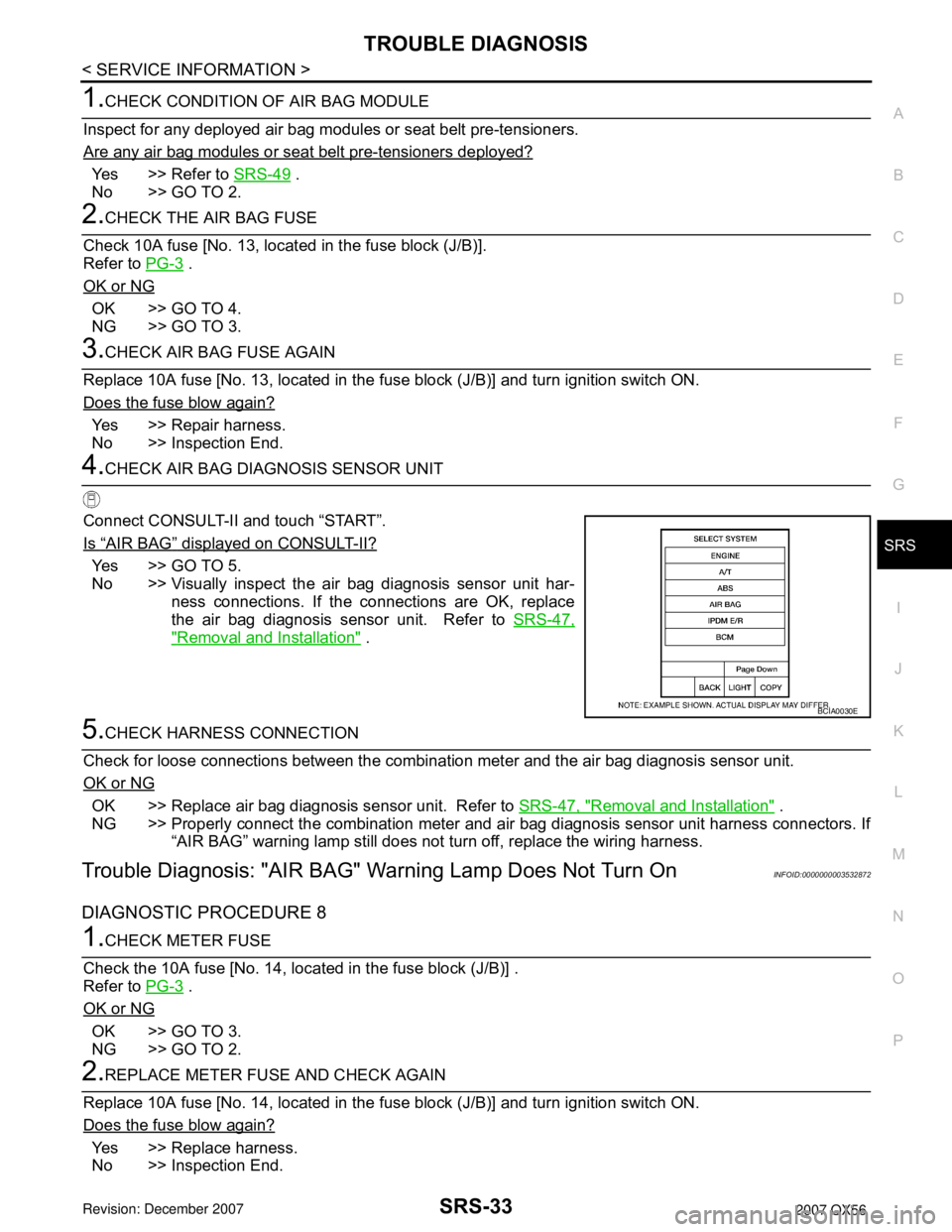
4.CHECK AIR BAG DIAGNOSIS SENSOR UNIT
Connect CONSULT-II and touch “START”.
Is
“AIR BAG” displayed on CONSULT-II?
Yes >> GO TO 5.
No >> Visually inspect the air bag diagnosis sensor unit har-
ness connections. If the connections are OK, replace
the air bag diagnosis sensor unit. Refer to SRS-47,
"Removal and Installation" .
5.CHECK HARNESS CONNECTION
Check for loose connections between the combination meter and the air bag diagnosis sensor unit.
OK or NG
OK >> Replace air bag diagnosis sensor unit. Refer to SRS-47, "Removal and Installation" .
NG >> Properly connect the combination meter and air bag diagnosis sensor unit harness connectors. If
“AIR BAG” warning lamp still does not turn off, replace the wiring harness.
Trouble Diagnosis: "AIR BAG" Warning Lamp Does Not Turn OnINFOID:0000000003532872
DIAGNOSTIC PROCEDURE 8
1.CHECK METER FUSE
Check the 10A fuse [No. 14, located in the fuse block (J/B)] .
Refer to PG-3
.
OK or NG
OK >> GO TO 3.
NG >> GO TO 2.
2.REPLACE METER FUSE AND CHECK AGAIN
Replace 10A fuse [No. 14, located in the fuse block (J/B)] and turn ignition switch ON.
Does the fuse blow again?
Yes >> Replace harness.
No >> Inspection End.
BCIA0030E