2007 INFINITI QX56 fuel pressure
[x] Cancel search: fuel pressurePage 1195 of 3061

EC-112
< SERVICE INFORMATION >
TROUBLE DIAGNOSIS
*: The following emission-related diagnostic information is cleared when the ECM memory is erased.
• Diagnostic trouble codes
• 1st trip diagnostic trouble codes
• Freeze frame data
• 1st trip freeze frame data
• System readiness test (SRT) codes
•Test values
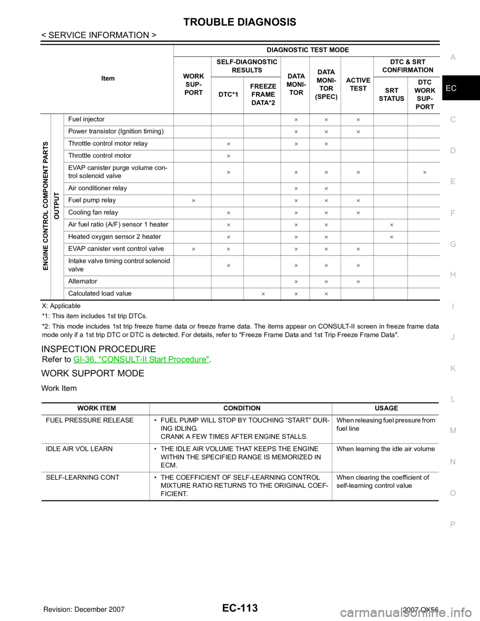
ENGINE CONTROL COMPONENT PARTS/CONTROL SYSTEMS APPLICATION
ItemDIAGNOSTIC TEST MODE
WORK
SUP-
PORTSELF-DIAGNOSTIC
RESULTS
DATA
MONI-
TORDATA
MONI-
TOR
(SPEC)ACTIVE
TESTDTC & SRT
CONFIRMATION
DTC*1FREEZE
FRAME
DATA*2SRT
STATUSDTC
WORK
SUP-
PORT
ENGINE CONTROL COMPONENT PARTS
INPUT
Crankshaft position sensor (POS)××××
Camshaft position sensor (PHASE)××××
Mass air flow sensor×××
Engine coolant temperature sensor×××××
Air fuel ratio (A/F) sensor 1×××××
Heated oxygen sensor 2×××××
Wheel sensor××××
Accelerator pedal position sensor×××
Throttle position sensor××××
Fuel tank temperature sensor××××
EVAP control system pressure sen-
sor×××
Intake air temperature sensor××××
Knock sensor×
Refrigerant pressure sensor××
Closed throttle position switch (ac-
celerator pedal position sensor sig-
nal)××
Air conditioner switch××
Park/neutral position (PNP) switch×××
Stop lamp switch×××
Power steering pressure sensor×××
Battery voltage××
Load signal××
Intake valve timing control position
sensor×××
Fuel level sensor×××
Battery current sensor×××
ICC steering switch×××
ASCD steering switch×××
ICC brake switch×××
ASCD brake switch×××
Page 1196 of 3061
TROUBLE DIAGNOSIS
EC-113
< SERVICE INFORMATION >
C
D
E
F
G
H
I
J
K
L
MA
EC
N
P O
X: Applicable
*1: This item includes 1st trip DTCs.
*2: This mode includes 1st trip freeze frame data or freeze frame data. The items appear on CONSULT-II screen in freeze frame data
mode only if a 1st trip DTC or DTC is detected. For details, refer to "Freeze Frame Data and 1st Trip Freeze Frame Data".
INSPECTION PROCEDURE
Refer to GI-36, "CONSULT-II Start Procedure".
WORK SUPPORT MODE
Work Item
ENGINE CONTROL COMPONENT PARTS
OUTPUT
Fuel injector×× ×
Power transistor (Ignition timing)×× ×
Throttle control motor relay×××
Throttle control motor×
EVAP canister purge volume con-
trol solenoid valve×××××
Air conditioner relay××
Fuel pump relay××××
Cooling fan relay××××
Air fuel ratio (A/F) sensor 1 heater××××
Heated oxygen sensor 2 heater××××
EVAP canister vent control valve×× ×××
Intake valve timing control solenoid
valve××××
Alternator×× ×
Calculated load value××× ItemDIAGNOSTIC TEST MODE
WORK
SUP-
PORTSELF-DIAGNOSTIC
RESULTS
DATA
MONI-
TORDATA
MONI-
TOR
(SPEC)ACTIVE
TESTDTC & SRT
CONFIRMATION
DTC*1FREEZE
FRAME
DATA*2SRT
STATUSDTC
WORK
SUP-
PORT
WORK ITEM CONDITION USAGE
FUEL PRESSURE RELEASE • FUEL PUMP WILL STOP BY TOUCHING “START” DUR-
ING IDLING.
CRANK A FEW TIMES AFTER ENGINE STALLS.When releasing fuel pressure from
fuel line
IDLE AIR VOL LEARN • THE IDLE AIR VOLUME THAT KEEPS THE ENGINE
WITHIN THE SPECIFIED RANGE IS MEMORIZED IN
ECM.When learning the idle air volume
SELF-LEARNING CONT • THE COEFFICIENT OF SELF-LEARNING CONTROL
MIXTURE RATIO RETURNS TO THE ORIGINAL COEF-
FICIENT.When clearing the coefficient of
self-learning control value
Page 1197 of 3061

EC-114
< SERVICE INFORMATION >
TROUBLE DIAGNOSIS
*: This function is not necessary in the usual service procedure.
SELF-DIAG RESULTS MODE
Self Diagnostic Item
Regarding items of DTC and 1st trip DTC, refer to EC-49, "Emission-related Diagnostic Information".
Freeze Frame Data and 1st Trip Freeze Frame Data
EVAP SYSTEM CLOSE CLOSE THE EVAP CANISTER VENT CONTROL VALVE IN
ORDER TO MAKE EVAP SYSTEM CLOSE UNDER THE
FOLLOWING CONDITIONS.
• IGN SW ON
• ENGINE NOT RUNNING
• AMBIENT TEMPERATURE IS ABOVE 0°C (32°F).
• NO VACUUM AND NO HIGH PRESSURE IN EVAP SYS-
TEM
• FUEL TANK TEMP. IS MORE THAN 0°C (32°F).
• WITHIN 10 MINUTES AFTER STARTING “EVAP SYS-
TEM CLOSE”
• WHEN TRYING TO EXECUTE “EVAP SYSTEM CLOSE”
UNDER THE CONDITION EXCEPT ABOVE, CONSULT-
II WILL DISCONTINUE IT AND DISPLAY APPROPRIATE
INSTRUCTION.
NOTE:
WHEN STARTING ENGINE, CONSULT-II MAY DISPLAY
“BATTERY VOLTAGE IS LOW. CHARGE BATTERY”,
EVEN IN USING CHARGED BATTERY.When detecting EVAP vapor leak
point of EVAP system
VIN REGISTRATION • IN THIS MODE, VIN IS REGISTERED IN ECM When registering VIN in ECM
TARGET IDLE RPM ADJ* • IDLE CONDITION When setting target idle speed
TARGET IGN TIM ADJ* • IDLE CONDITION When adjusting target ignition tim-
ing WORK ITEM CONDITION USAGE
Freeze frame data
item*Description
DIAG TROUBLE
CODE
[PXXXX]• The engine control component part/control system has a trouble code, it is displayed as PXXXX. (Refer to
EC-9
.)
FUEL SYS-B1 • “Fuel injection system status” at the moment a malfunction is detected is displayed.
• One mode in the following is displayed.
Mode2: Open loop due to detected system malfunction
Mode3: Open loop due to driving conditions (power enrichment, deceleration enleanment)
Mode4: Closed loop - using oxygen sensor(s) as feedback for fuel control
Mode5: Open loop - has not yet satisfied condition to go to closed loop FUEL SYS-B2
CAL/LD VALUE [%] • The calculated load value at the moment a malfunction is detected is displayed.
COOLANT TEMP
[°C] or [°F]• The engine coolant temperature at the moment a malfunction is detected is displayed.
L-FUEL TRM-B1 [%] • “Long-term fuel trim” at the moment a malfunction is detected is displayed.
• The long-term fuel trim indicates much more gradual feedback compensation to the base fuel schedule than
short-term fuel trim. L-FUEL TRM-B2 [%]
S-FUEL TRM-B1 [%] • “Short-term fuel trim” at the moment a malfunction is detected is displayed.
• The short-term fuel trim indicates dynamic or instantaneous feedback compensation to the base fuel sched-
ule. S-FUEL TRM-B2 [%]
ENGINE SPEED [rpm] • The engine speed at the moment a malfunction is detected is displayed.
VEHICL SPEED
[km/h] or [mph]• The vehicle speed at the moment a malfunction is detected is displayed.
ABSOL TH-P/S
[%]• The throttle valve opening at the moment a malfunction is detected is displayed.
Page 1199 of 3061
![INFINITI QX56 2007 Factory Service Manual EC-116
< SERVICE INFORMATION >
TROUBLE DIAGNOSIS
FUEL T/TMP SE
[°C] or [°F]ו The fuel temperature (determined by the
signal voltage of the fuel tank tempera-
ture sensor) is displayed.
INT/A T INFINITI QX56 2007 Factory Service Manual EC-116
< SERVICE INFORMATION >
TROUBLE DIAGNOSIS
FUEL T/TMP SE
[°C] or [°F]ו The fuel temperature (determined by the
signal voltage of the fuel tank tempera-
ture sensor) is displayed.
INT/A T](/manual-img/42/57029/w960_57029-1198.png)
EC-116
< SERVICE INFORMATION >
TROUBLE DIAGNOSIS
FUEL T/TMP SE
[°C] or [°F]ו The fuel temperature (determined by the
signal voltage of the fuel tank tempera-
ture sensor) is displayed.
INT/A TEMP SE
[°C] or [°F]×ו The intake air temperature (determined
by the signal voltage of the intake air
temperature sensor) is indicated.
EVAP SYS PRES
[V]ו The signal voltage of EVAP control sys-
tem pressure sensor is displayed.
FUEL LEVEL SE [V]ו The signal voltage of the fuel level sen-
sor is displayed.
START SIGNAL
[ON/OFF]×ו Indicates start signal status [ON/OFF]
computed by the ECM according to the
signals of engine speed and battery volt-
age.• After starting the engine, [OFF] is dis-
played regardless of the starter signal.
CLSD THL POS
[ON/OFF]×ו Indicates idle position [ON/OFF] comput-
ed by ECM according to the accelerator
pedal position sensor signal.
AIR COND SIG
[ON/OFF]×ו Indicates [ON/OFF] condition of the air
conditioner switch as determined by the
air conditioner signal.
P/N POSI SW
[ON/OFF]×ו Indicates [ON/OFF] condition from the
park/neutral position (PNP) switch sig-
nal.
PW/ST SIGNAL
[ON/OFF]×ו [ON/OFF] condition of the power steering
system (determined by the signal voltage
of the power steering pressure sensor
signal) is indicated.
LOAD SIGNAL [ON/
OFF]×ו Indicates [ON/OFF] condition from the
electrical load signal.
ON: Rear window defogger switch is ON
and/or lighting switch is in 2nd position.
OFF: Both rear window defogger switch
and lighting switch are OFF.
IGNITION SW
[ON/OFF]ו Indicates [ON/OFF] condition from igni-
tion switch signal.
HEATER FAN SW
[ON/OFF]ו Indicates [ON/OFF] condition from heat-
er fan switch signal.
BRAKE SW
[ON/OFF]ו Indicates [ON/OFF] condition from the
stop lamp switch signal.
INJ PULSE-B1
[msec]×
• Indicates the actual fuel injection pulse
width compensated by ECM according to
the input signals.• When the engine is stopped, a certain
computed value is indicated.
INJ PULSE-B2
[msec]
IGN TIMING [BT-
DC]ו Indicates the ignition timing computed by
ECM according to the input signals.• When the engine is stopped, a certain
value is indicated.
CAL/LD VALUE [%]• “Calculated load value” indicates the val-
ue of the current air flow divided by peak
air flow.
MASS AIRFLOW
[g·m/s]• Indicates the mass air flow computed by
ECM according to the signal voltage of
the mass air flow sensor. Monitored item
[Unit]ECM IN-
PUT SIG-
NALSMAIN
SIGNALSDescription Remarks
Page 1206 of 3061
TROUBLE DIAGNOSIS
EC-123
< SERVICE INFORMATION >
C
D
E
F
G
H
I
J
K
L
MA
EC
N
P O
INSPECTION PROCEDURE
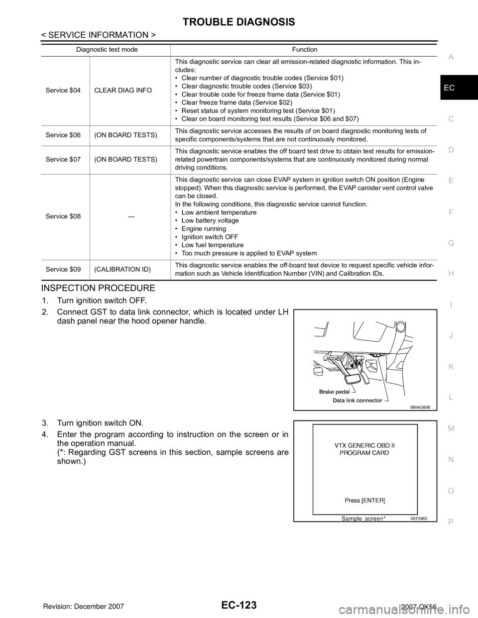
1. Turn ignition switch OFF.
2. Connect GST to data link connector, which is located under LH
dash panel near the hood opener handle.
3. Turn ignition switch ON.
4. Enter the program according to instruction on the screen or in
the operation manual.
(*: Regarding GST screens in this section, sample screens are
shown.)
Service $04 CLEAR DIAG INFOThis diagnostic service can clear all emission-related diagnostic information. This in-
cludes:
• Clear number of diagnostic trouble codes (Service $01)
• Clear diagnostic trouble codes (Service $03)
• Clear trouble code for freeze frame data (Service $01)
• Clear freeze frame data (Service $02)
• Reset status of system monitoring test (Service $01)
• Clear on board monitoring test results (Service $06 and $07)
Service $06 (ON BOARD TESTS)This diagnostic service accesses the results of on board diagnostic monitoring tests of
specific components/systems that are not continuously monitored.
Service $07 (ON BOARD TESTS)This diagnostic service enables the off board test drive to obtain test results for emission-
related powertrain components/systems that are continuously monitored during normal
driving conditions.
Service $08 —This diagnostic service can close EVAP system in ignition switch ON position (Engine
stopped). When this diagnostic service is performed, the EVAP canister vent control valve
can be closed.
In the following conditions, this diagnostic service cannot function.
• Low ambient temperature
• Low battery voltage
• Engine running
• Ignition switch OFF
• Low fuel temperature
• Too much pressure is applied to EVAP system
Service $09 (CALIBRATION ID)This diagnostic service enables the off-board test device to request specific vehicle infor-
mation such as Vehicle Identification Number (VIN) and Calibration IDs. Diagnostic test mode Function
BBIA0369E
SEF398S
Page 1212 of 3061
TROUBLE DIAGNOSIS - SPECIFICATION VALUE
EC-129
< SERVICE INFORMATION >
C
D
E
F
G
H
I
J
K
L
MA
EC
N
P O
TROUBLE DIAGNOSIS - SPECIFICATION VALUE
DescriptionINFOID:0000000003531630
The specification (SP) value indicates the tolerance of the value that is displayed in “DATA MONITOR (SPEC)”
mode of CONSULT-II during normal operation of the Engine Control System. When the value in “DATA MONI-
TOR (SPEC)” mode is within the SP value, the Engine Control System is confirmed OK. When the value in
“DATA MONITOR (SPEC)” mode is NOT within the SP value, the Engine Control System may have one or
more malfunctions.
The SP value is used to detect malfunctions that may affect the Engine Control System, but will not light the
MIL.
The SP value will be displayed for the following three items:
• B/FUEL SCHDL (The fuel injection pulse width programmed into ECM prior to any learned on board correc-
tion)
• A/F ALPHA-B1/B2 (The mean value of air-fuel ratio feedback correction factor per cycle)
• MAS A/F SE-B1 (The signal voltage of the mass air flow sensor)
Testing ConditionINFOID:0000000003531631
• Vehicle driven distance: More than 5,000 km (3,107 miles)
• Barometric pressure: 98.3 - 104.3 kPa (1.003 - 1.064 kg/cm
2 , 14.25 - 15.12 psi)
• Atmospheric temperature: 20 - 30°C (68 - 86°F)
• Engine coolant temperature: 75 - 95°C (167 - 203°F)
• Engine speed: Idle
• Transmission: Warmed-up
- After the engine is warmed up to normal operating temperature, drive vehicle until “ATF TEMP SE 1” (A/T
fluid temperature sensor signal) indicates more than 60°C (140°F).
• Electrical load: Not applied
- Rear window defogger switch, air conditioner switch, lighting switch are OFF. Steering wheel is straight
ahead.
Inspection ProcedureINFOID:0000000003531632
NOTE:
Perform “DATA MONITOR (SPEC)” mode in maximum scale display.
1. Perform EC-71, "
Basic Inspection" .
2. Confirm that the testing conditions indicated above are met.
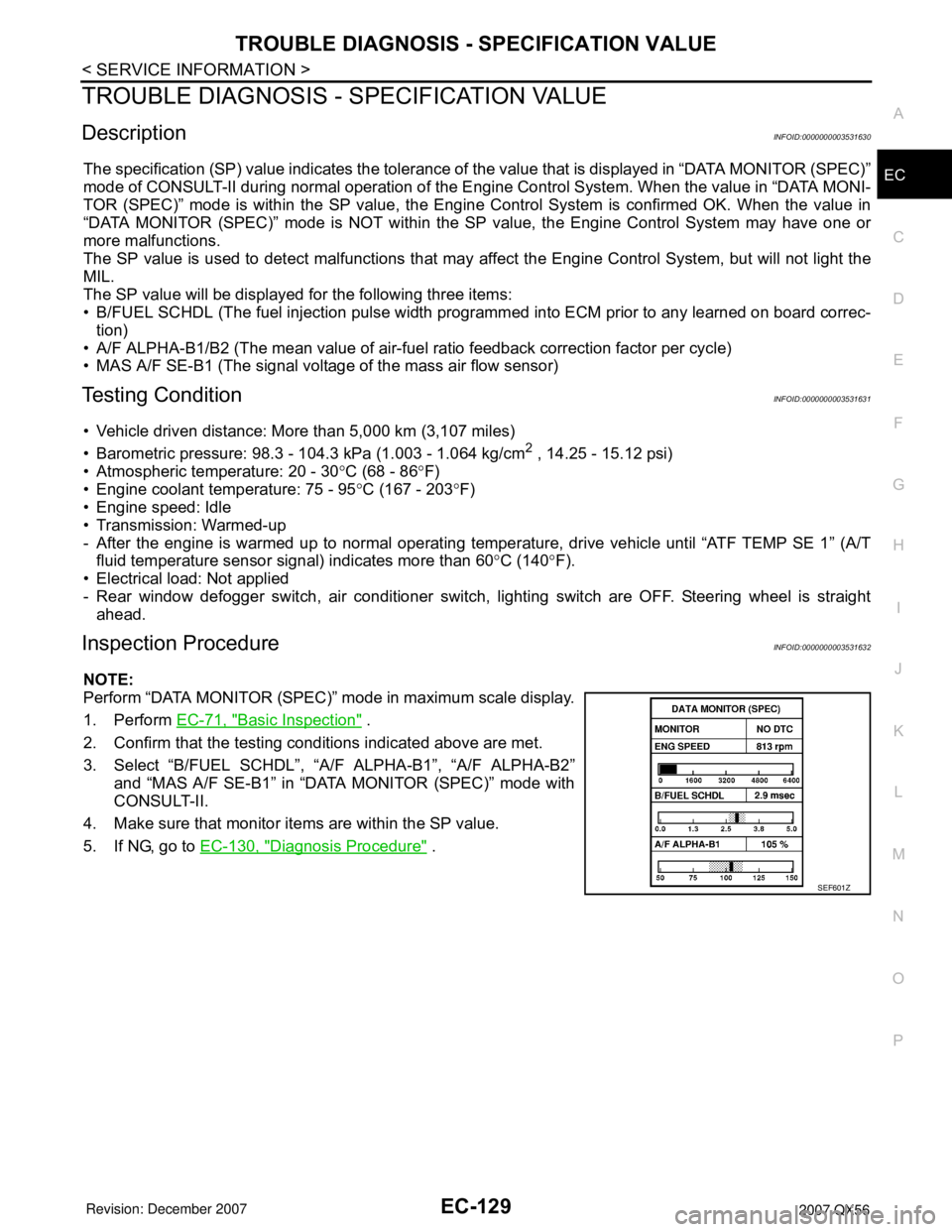
3. Select “B/FUEL SCHDL”, “A/F ALPHA-B1”, “A/F ALPHA-B2”
and “MAS A/F SE-B1” in “DATA MONITOR (SPEC)” mode with
CONSULT-II.
4. Make sure that monitor items are within the SP value.
5. If NG, go to EC-130, "
Diagnosis Procedure" .
SEF601Z
Page 1216 of 3061
TROUBLE DIAGNOSIS - SPECIFICATION VALUE
EC-133
< SERVICE INFORMATION >
C
D
E
F
G
H
I
J
K
L
MA
EC
N
P O
6.CHECK FUEL PRESSURE
Check fuel pressure. (Refer to EC-80, "
Fuel Pressure Check" .)
OK or NG
OK >> GO TO 9.
NG (Fuel pressure is too high)>>Replace fuel pressure regulator, refer to EC-80, "
Fuel Pressure Check" .
GO TO 8.
NG (Fuel pressure is too low)>>GO TO 7.
7.DETECT MALFUNCTIONING PART
1. Check the following.
- Clogged and bent fuel hose and fuel tube
- Clogged fuel filter
- Fuel pump and its circuit (Refer to EC-613
.)
2. If NG, repair or replace the malfunctioning part. (Refer to EC-80, "
Fuel Pressure Check" .)
If OK, replace fuel pressure regulator.
>> GO TO 8.
8.CHECK “A/F ALPHA-B1”, “A/F ALPHA-B2”
1. Start engine.
2. Select “A/F ALPHA-B1”, “A/F ALPHA-B2” in “DATA MONITOR (SPEC)” mode, and make sure that the
each indication is within the SP value.
OK or NG
OK >>INSPECTION END
NG >> GO TO 9.
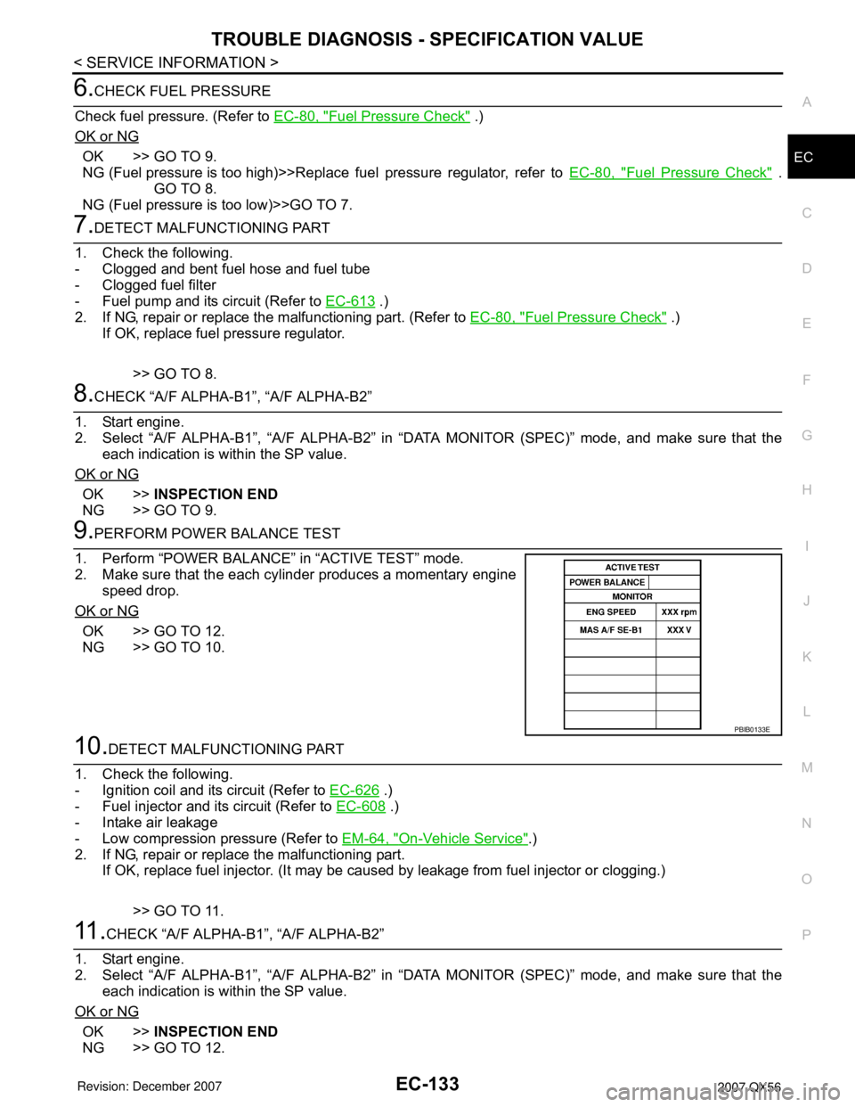
9.PERFORM POWER BALANCE TEST
1. Perform “POWER BALANCE” in “ACTIVE TEST” mode.
2. Make sure that the each cylinder produces a momentary engine
speed drop.
OK or NG
OK >> GO TO 12.
NG >> GO TO 10.
10.DETECT MALFUNCTIONING PART
1. Check the following.
- Ignition coil and its circuit (Refer to EC-626
.)
- Fuel injector and its circuit (Refer to EC-608
.)
- Intake air leakage
- Low compression pressure (Refer to EM-64, "
On-Vehicle Service".)
2. If NG, repair or replace the malfunctioning part.
If OK, replace fuel injector. (It may be caused by leakage from fuel injector or clogging.)
>> GO TO 11.
11 .CHECK “A/F ALPHA-B1”, “A/F ALPHA-B2”
1. Start engine.
2. Select “A/F ALPHA-B1”, “A/F ALPHA-B2” in “DATA MONITOR (SPEC)” mode, and make sure that the
each indication is within the SP value.
OK or NG
OK >>INSPECTION END
NG >> GO TO 12.
PBIB0133E
Page 1333 of 3061
EC-250
< SERVICE INFORMATION >
DTC P0133, P0153 A/F SENSOR 1
DTC P0133, P0153 A/F SENSOR 1
Component DescriptionINFOID:0000000003531758
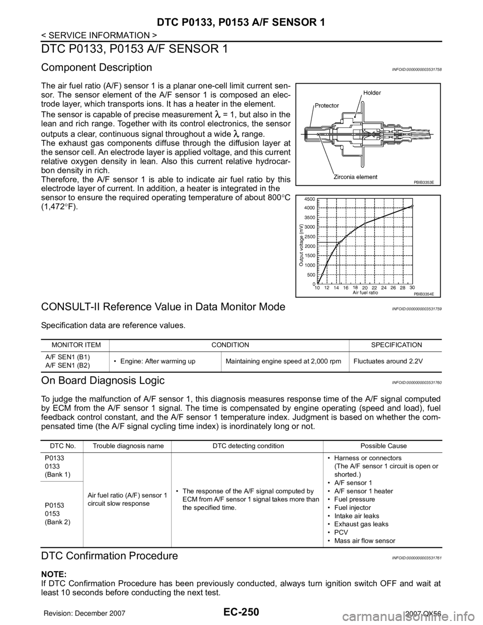
The air fuel ratio (A/F) sensor 1 is a planar one-cell limit current sen-
sor. The sensor element of the A/F sensor 1 is composed an elec-
trode layer, which transports ions. It has a heater in the element.
The sensor is capable of precise measurement = 1, but also in the
lean and rich range. Together with its control electronics, the sensor
outputs a clear, continuous signal throughout a wide range.
The exhaust gas components diffuse through the diffusion layer at
the sensor cell. An electrode layer is applied voltage, and this current
relative oxygen density in lean. Also this current relative hydrocar-
bon density in rich.
Therefore, the A/F sensor 1 is able to indicate air fuel ratio by this
electrode layer of current. In addition, a heater is integrated in the
sensor to ensure the required operating temperature of about 800°C
(1,472°F).
CONSULT-II Reference Value in Data Monitor ModeINFOID:0000000003531759
Specification data are reference values.
On Board Diagnosis LogicINFOID:0000000003531760
To judge the malfunction of A/F sensor 1, this diagnosis measures response time of the A/F signal computed
by ECM from the A/F sensor 1 signal. The time is compensated by engine operating (speed and load), fuel
feedback control constant, and the A/F sensor 1 temperature index. Judgment is based on whether the com-
pensated time (the A/F signal cycling time index) is inordinately long or not.
DTC Confirmation ProcedureINFOID:0000000003531761
NOTE:
If DTC Confirmation Procedure has been previously conducted, always turn ignition switch OFF and wait at
least 10 seconds before conducting the next test.
PBIB3353E
PBIB3354E
MONITOR ITEM CONDITION SPECIFICATION
A/F SEN1 (B1)
A/F SEN1 (B2)• Engine: After warming up Maintaining engine speed at 2,000 rpm Fluctuates around 2.2V
DTC No. Trouble diagnosis name DTC detecting condition Possible Cause
P0133
0133
(Bank 1)
Air fuel ratio (A/F) sensor 1
circuit slow response• The response of the A/F signal computed by
ECM from A/F sensor 1 signal takes more than
the specified time.• Harness or connectors
(The A/F sensor 1 circuit is open or
shorted.)
• A/F sensor 1
• A/F sensor 1 heater
• Fuel pressure
• Fuel injector
• Intake air leaks
• Exhaust gas leaks
•PCV
• Mass air flow sensor P0153
0153
(Bank 2)