2007 INFINITI QX56 fuel pressure
[x] Cancel search: fuel pressurePage 1024 of 3061
COMBINATION METERSDI-13
< SERVICE INFORMATION >
C
DE
F
G H
I
J
L
M A
B
DI
N
O P
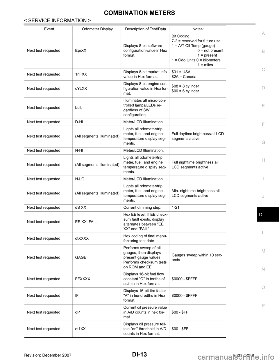
Next test requested EprXX Displays 8-bit software
configuration value in Hex
format.Bit Coding
7-2 = reserved for future use
1 = A/T Oil Temp (gauge)
0 = not present
1 = present
1 = Odo Units 0 = kilometers
1 = miles
Next test requested 1nFXX Displays 8-bit market info
value in Hex format.$31 = USA
$2A = Canada
Next test requested cYLXX Displays 8-bit engine con-
figuration value in Hex for-
mat.$08 = 8 cylinder
$06 = 6 cylinder
Next test requested bulb Illuminates all micro-con-
trolled lamps/LEDs re-
gardless of SW
configuration.
Next test requested D-HI Meter/LCD Illumination.
Next test requested (All segments illuminated) Lights all odometer/trip
meter, fuel, and engine
temperature display seg-
ments.Full daytime brightness all LCD
segments active
Next test requested N-HI Meter/LCD Illumination.
Next test requested (All segments illuminated) Lights all odometer/trip
meter, fuel, and engine
temperature display seg-
ments.Full nighttime brightness all
LCD segments active
Next test requested N-LO Meter/LCD Illumination.
Next test requested (All segments illuminated) Lights all odometer/trip
meter, fuel, and engine
temperature display seg-
ments.Min. nighttime brightness all
LCD segments active
Next test requested dS XX Current dimming step. 1-21
Next test requested EE XX, FAIL Hex EE level. If EE check-
sum fault exists, display
alternates between "EE
XX" and "FAIL".
Next test requested dtXXXX Hex coding of final manu-
facturing test date.
Next test requested GAGE Performs sweep of all
gauges, then displays
present gauge values.
Performs checksum tests
on ROM and EE.Gauges sweep within 10 sec-
onds
Next test requested FFXXXX Displays 16-bit fuel flow
constant "Q" in tenths of
cc/min in Hex format.$0000 - $FFFF
Next test requested tF Displays 16-bit tire factor
"A" in hundredths in Hex
format.$0000 - $FFFF
Next test requested oP Current oil pressure value
in A/D counts in hex for-
mat.
$00 - $FF
Next test requested ot1XX Displays oil pressure tell-
tale "on" threshold in A/D
counts in Hex format.$00 - $FF
Event Odometer Display Description of Test/Data Notes:
Page 1025 of 3061

DI-14
< SERVICE INFORMATION >
COMBINATION METERS
Next test requested ot0XXDisplays oil pressure tell-
tale "off" threshold in A/D
counts in Hex format.$00 - $FF
Next test requested XXXXX Raw uncompensated en-
glish speed value in hun-
dredths of MPH.
Speedometer indicates
present speed.Will display "-----"
if message is
not received. Will display
"99999" if data received is in-
valid
Next test requested XXXXX Raw uncompensated
metric speed value in hun-
dredths of KPH. Speed-
ometer indicates present
speed.Will display "-----"
if message is
not received. Will display
"99999" if data received is in-
valid
Next test requested tXXXX Tachometer value in
RPM. Tachometer indi-
cates present RPM.Will display "-----"
if message is
not received.
Next test requested F1 XXXX Present ratioed fuel level
A/D input 1 in decimal for-
mat. Fuel gauge indicates
present filtered level.000-009 = Short circuit
010-254 = Normal range
255 = Open circuit
--- = Missing 5 seconds
Next test requested F2 XXX Present FLPS. 010-254 normal range
Next test requested FS X Fuel filter rate 0 = Normal
1 = Fast
Next test requested XXXC Last temperature gauge
input value in degrees C.
Temperature gauge indi-
cates present filtered tem-
perature.Will display "---"
C if message is
not received.
Will display "999" if data re-
ceived is invalid.
Next test requested BAtXX.X Estimated present battery
voltage.
Next test requested rES -X Seat belt buckle switch LH
status.0 = Unbuckled
1 = Buckled
Next test requested PA -XX Hex value port A.
Next test requested Pb -XX Hex value port B.
Next test requested PE -XX Hex value port E.
Next test requested PL -XX Hex value port L.
Next test requested P6 -XX Hex value port K.
Next test requested Pn -XX Hex value port M.
Next test requested PP -XX Hex value port P.
Next test requested PS -XX Hex value port S.
Next test requested Pt -XX Hex value port T.
Next test requested Pu -XX Hex value port U.
Next test requested P4 -XX Hex value port V.
Next test requested Puu -XX Hex value port W.
Next test requested A00XXX A/D port A/D value (non-
ratioed).0-255
Next test requested A01XXX A/D port A/D value (non-
ratioed).
0-255
Next test requested A02XXX A/D port A/D value (non-
ratioed).0-255
Next test requested A03XXX A/D port A/D value (non-
ratioed).0-255
Event Odometer Display Description of Test/Data Notes:
Page 1029 of 3061
DI-18
< SERVICE INFORMATION >
COMBINATION METERS
Self-diagnostic results content
No malfunction detected>>GO TO 2.
Malfunction detected>>GO TO PG-18, "
CONSULT-II Function (IPDM E/R)".
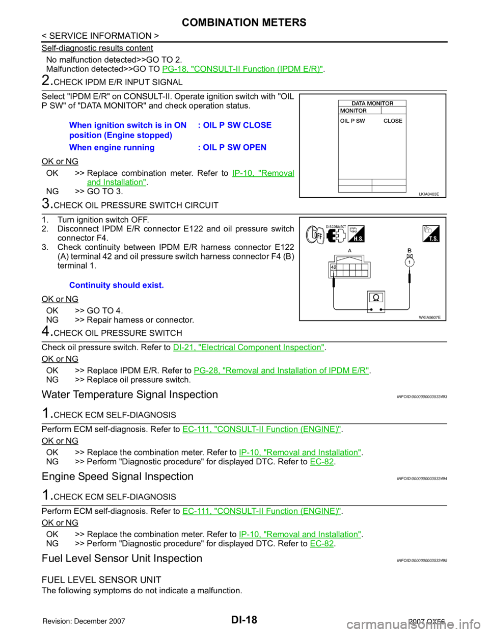
2.CHECK IPDM E/R INPUT SIGNAL
Select "IPDM E/R" on CONSULT-II. Operate ignition switch with "OIL
P SW" of "DATA MONITOR" and check operation status.
OK or NG
OK >> Replace combination meter. Refer to IP-10, "Removal
and Installation".
NG >> GO TO 3.
3.CHECK OIL PRESSURE SWITCH CIRCUIT
1. Turn ignition switch OFF.
2. Disconnect IPDM E/R connector E122 and oil pressure switch
connector F4.
3. Check continuity between IPDM E/R harness connector E122 (A) terminal 42 and oil pressure switch harness connector F4 (B)
terminal 1.
OK or NG
OK >> GO TO 4.
NG >> Repair harness or connector.
4.CHECK OIL PRESSURE SWITCH
Check oil pressure switch. Refer to DI-21, "
Electrical Component Inspection".
OK or NG
OK >> Replace IPDM E/R. Refer to PG-28, "Removal and Installation of IPDM E/R".
NG >> Replace oil pressure switch.
Water Temperature Signal InspectionINFOID:0000000003533493
1.CHECK ECM SELF-DIAGNOSIS
Perform ECM self-diagnosis. Refer to E C - 111 , "
CONSULT-II Function (ENGINE)".
OK or NG
OK >> Replace the combination meter. Refer to IP-10, "Removal and Installation".
NG >> Perform "Diagnostic procedure" for displayed DTC. Refer to EC-82
.
Engine Speed Signal InspectionINFOID:0000000003533494
1.CHECK ECM SELF-DIAGNOSIS
Perform ECM self-diagnosis. Refer to E C - 111 , "
CONSULT-II Function (ENGINE)".
OK or NG
OK >> Replace the combination meter. Refer to IP-10, "Removal and Installation".
NG >> Perform "Diagnostic procedure" for displayed DTC. Refer to EC-82
.
Fuel Level Sensor Unit InspectionINFOID:0000000003533495
FUEL LEVEL SENSOR UNIT
The following symptoms do not indicate a malfunction.When ignition switch is in ON
position (Engine stopped)
: OIL P SW CLOSE
When engine running : OIL P SW OPEN
LKIA0403E
Continuity should exist.
WKIA5607E
Page 1032 of 3061
COMBINATION METERS
DI-21
< SERVICE INFORMATION >
C
D
E
F
G
H
I
J
L
MA
B
DI
N
O
P
4.CHECK POINTER MOVEMENT TO EMPTY-POSITION
During driving, does the fuel gauge move gradually toward empty-position?
YES or NO
YES >> Check the fuel level sensor unit. Refer to DI-21, "Electrical Component Inspection".
NO >> Check fuel level sensor unit installation, and determine whether the float arm interferes or binds
with any of the internal components in the fuel tank.
Electrical Component InspectionINFOID:0000000003533498
FUEL LEVEL SENSOR UNIT CHECK
For removal, refer to FL-5, "Removal and Installation".
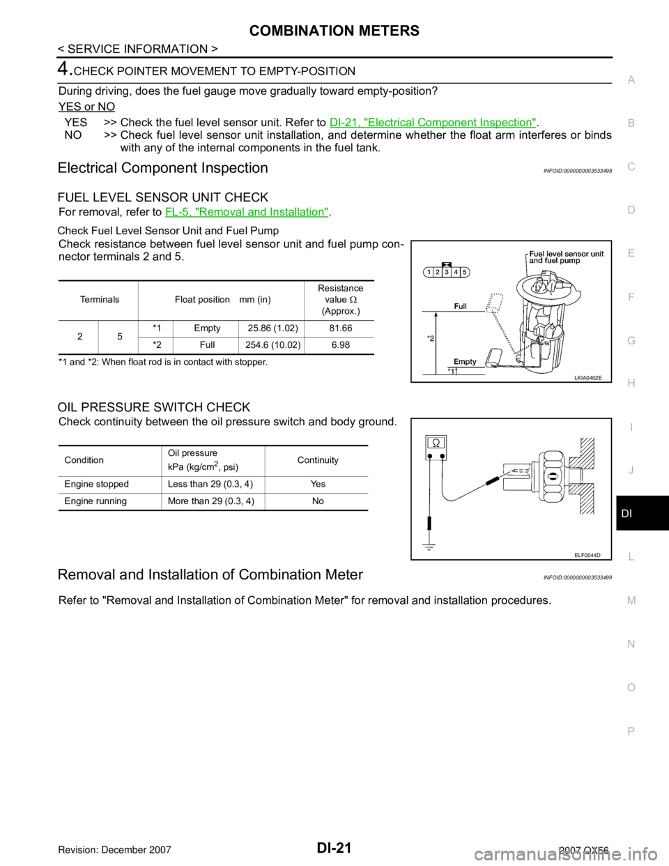
Check Fuel Level Sensor Unit and Fuel Pump
Check resistance between fuel level sensor unit and fuel pump con-
nector terminals 2 and 5.
*1 and *2: When float rod is in contact with stopper.
OIL PRESSURE SWITCH CHECK
Check continuity between the oil pressure switch and body ground.
Removal and Installation of Combination MeterINFOID:0000000003533499
Refer to "Removal and Installation of Combination Meter" for removal and installation procedures.
Terminals Float position mm (in)Resistance
value Ω
(Approx.)
25*1 Empty 25.86 (1.02) 81.66
*2 Full 254.6 (10.02) 6.98
LKIA0402E
ConditionOil pressure
kPa (kg/cm2, psi)Continuity
Engine stopped Less than 29 (0.3, 4) Yes
Engine running More than 29 (0.3, 4) No
ELF0044D
Page 1084 of 3061
EC-1
ENGINE
C
D
E
F
G
H
I
J
K
L
M
SECTION EC
A
EC
N
O
P
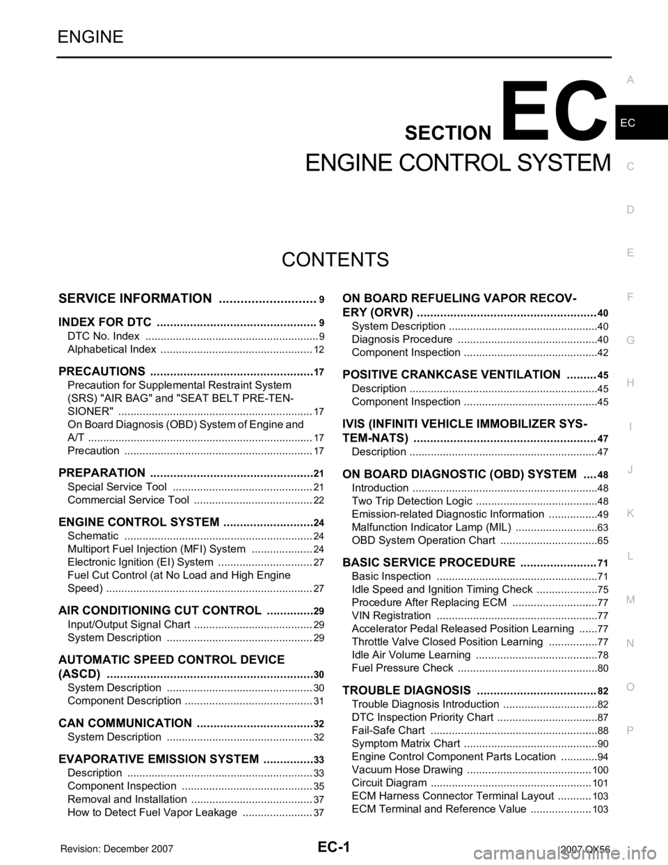
CONTENTS
ENGINE CONTROL SYSTEM
SERVICE INFORMATION ............................9
INDEX FOR DTC .................................................9
DTC No. Index ..........................................................9
Alphabetical Index ...................................................12
PRECAUTIONS ..................................................17
Precaution for Supplemental Restraint System
(SRS) "AIR BAG" and "SEAT BELT PRE-TEN-
SIONER" .................................................................
17
On Board Diagnosis (OBD) System of Engine and
A/T ...........................................................................
17
Precaution ...............................................................17
PREPARATION ..................................................21
Special Service Tool ...............................................21
Commercial Service Tool ........................................22
ENGINE CONTROL SYSTEM ............................24
Schematic ...............................................................24
Multiport Fuel Injection (MFI) System .....................24
Electronic Ignition (EI) System ................................27
Fuel Cut Control (at No Load and High Engine
Speed) .....................................................................
27
AIR CONDITIONING CUT CONTROL ...............29
Input/Output Signal Chart ........................................29
System Description .................................................29
AUTOMATIC SPEED CONTROL DEVICE
(ASCD) ...............................................................
30
System Description .................................................30
Component Description ...........................................31
CAN COMMUNICATION ....................................32
System Description .................................................32
EVAPORATIVE EMISSION SYSTEM ................33
Description ..............................................................33
Component Inspection ............................................35
Removal and Installation .........................................37
How to Detect Fuel Vapor Leakage ........................37
ON BOARD REFUELING VAPOR RECOV-
ERY (ORVR) ......................................................
40
System Description ..................................................40
Diagnosis Procedure ...............................................40
Component Inspection .............................................42
POSITIVE CRANKCASE VENTILATION .........45
Description ...............................................................45
Component Inspection .............................................45
IVIS (INFINITI VEHICLE IMMOBILIZER SYS-
TEM-NATS) .......................................................
47
Description ...............................................................47
ON BOARD DIAGNOSTIC (OBD) SYSTEM ....48
Introduction ..............................................................48
Two Trip Detection Logic .........................................48
Emission-related Diagnostic Information .................49
Malfunction Indicator Lamp (MIL) ............................63
OBD System Operation Chart .................................65
BASIC SERVICE PROCEDURE .......................71
Basic Inspection ......................................................71
Idle Speed and Ignition Timing Check .....................75
Procedure After Replacing ECM .............................77
VIN Registration ......................................................77
Accelerator Pedal Released Position Learning .......77
Throttle Valve Closed Position Learning .................77
Idle Air Volume Learning .........................................78
Fuel Pressure Check ...............................................80
TROUBLE DIAGNOSIS ....................................82
Trouble Diagnosis Introduction ................................82
DTC Inspection Priority Chart ..................................87
Fail-Safe Chart ........................................................88
Symptom Matrix Chart .............................................90
Engine Control Component Parts Location .............94
Vacuum Hose Drawing ..........................................100
Circuit Diagram ......................................................101
ECM Harness Connector Terminal Layout ............103
ECM Terminal and Reference Value .....................103
Page 1088 of 3061
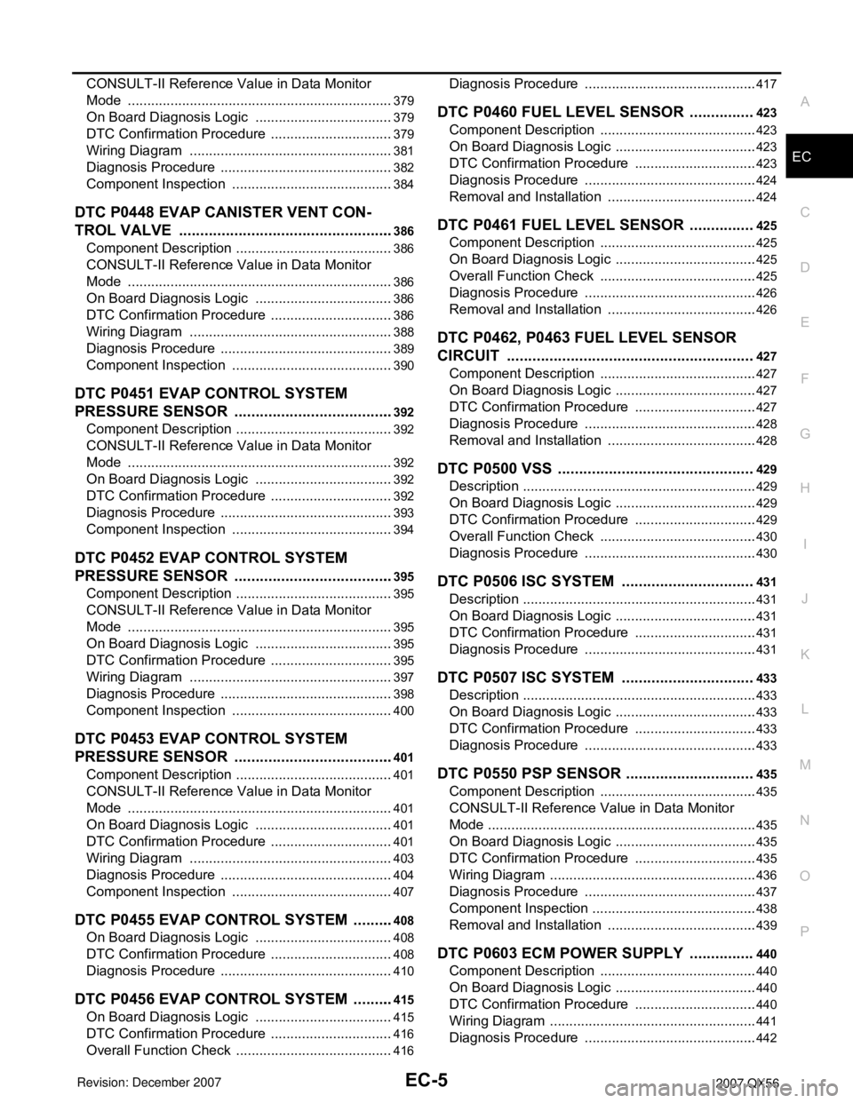
EC-5
C
D
E
F
G
H
I
J
K
L
M
ECA
N
O
P CONSULT-II Reference Value in Data Monitor
Mode .....................................................................
379
On Board Diagnosis Logic ....................................379
DTC Confirmation Procedure ................................379
Wiring Diagram .....................................................381
Diagnosis Procedure .............................................382
Component Inspection ..........................................384
DTC P0448 EVAP CANISTER VENT CON-
TROL VALVE ...................................................
386
Component Description .........................................386
CONSULT-II Reference Value in Data Monitor
Mode .....................................................................
386
On Board Diagnosis Logic ....................................386
DTC Confirmation Procedure ................................386
Wiring Diagram .....................................................388
Diagnosis Procedure .............................................389
Component Inspection ..........................................390
DTC P0451 EVAP CONTROL SYSTEM
PRESSURE SENSOR ......................................
392
Component Description .........................................392
CONSULT-II Reference Value in Data Monitor
Mode .....................................................................
392
On Board Diagnosis Logic ....................................392
DTC Confirmation Procedure ................................392
Diagnosis Procedure .............................................393
Component Inspection ..........................................394
DTC P0452 EVAP CONTROL SYSTEM
PRESSURE SENSOR ......................................
395
Component Description .........................................395
CONSULT-II Reference Value in Data Monitor
Mode .....................................................................
395
On Board Diagnosis Logic ....................................395
DTC Confirmation Procedure ................................395
Wiring Diagram .....................................................397
Diagnosis Procedure .............................................398
Component Inspection ..........................................400
DTC P0453 EVAP CONTROL SYSTEM
PRESSURE SENSOR ......................................
401
Component Description .........................................401
CONSULT-II Reference Value in Data Monitor
Mode .....................................................................
401
On Board Diagnosis Logic ....................................401
DTC Confirmation Procedure ................................401
Wiring Diagram .....................................................403
Diagnosis Procedure .............................................404
Component Inspection ..........................................407
DTC P0455 EVAP CONTROL SYSTEM ..........408
On Board Diagnosis Logic ....................................408
DTC Confirmation Procedure ................................408
Diagnosis Procedure .............................................410
DTC P0456 EVAP CONTROL SYSTEM ..........415
On Board Diagnosis Logic ....................................415
DTC Confirmation Procedure ................................416
Overall Function Check .........................................416
Diagnosis Procedure .............................................417
DTC P0460 FUEL LEVEL SENSOR ...............423
Component Description .........................................423
On Board Diagnosis Logic .....................................423
DTC Confirmation Procedure ................................423
Diagnosis Procedure .............................................424
Removal and Installation .......................................424
DTC P0461 FUEL LEVEL SENSOR ...............425
Component Description .........................................425
On Board Diagnosis Logic .....................................425
Overall Function Check .........................................425
Diagnosis Procedure .............................................426
Removal and Installation .......................................426
DTC P0462, P0463 FUEL LEVEL SENSOR
CIRCUIT ..........................................................
427
Component Description .........................................427
On Board Diagnosis Logic .....................................427
DTC Confirmation Procedure ................................427
Diagnosis Procedure .............................................428
Removal and Installation .......................................428
DTC P0500 VSS ..............................................429
Description .............................................................429
On Board Diagnosis Logic .....................................429
DTC Confirmation Procedure ................................429
Overall Function Check .........................................430
Diagnosis Procedure .............................................430
DTC P0506 ISC SYSTEM ...............................431
Description .............................................................431
On Board Diagnosis Logic .....................................431
DTC Confirmation Procedure ................................431
Diagnosis Procedure .............................................431
DTC P0507 ISC SYSTEM ...............................433
Description .............................................................433
On Board Diagnosis Logic .....................................433
DTC Confirmation Procedure ................................433
Diagnosis Procedure .............................................433
DTC P0550 PSP SENSOR ..............................435
Component Description .........................................435
CONSULT-II Reference Value in Data Monitor
Mode ......................................................................
435
On Board Diagnosis Logic .....................................435
DTC Confirmation Procedure ................................435
Wiring Diagram ......................................................436
Diagnosis Procedure .............................................437
Component Inspection ...........................................438
Removal and Installation .......................................439
DTC P0603 ECM POWER SUPPLY ...............440
Component Description .........................................440
On Board Diagnosis Logic .....................................440
DTC Confirmation Procedure ................................440
Wiring Diagram ......................................................441
Diagnosis Procedure .............................................442
Page 1091 of 3061

EC-8
DTC Confirmation Procedure ................................567
Wiring Diagram ......................................................569
Diagnosis Procedure .............................................570
Component Inspection ...........................................572
Removal and Installation .......................................573
DTC P2135 TP SENSOR .................................574
Component Description .........................................574
CONSULT-II Reference Value in Data Monitor
Mode ......................................................................
574
On Board Diagnosis Logic .....................................574
DTC Confirmation Procedure ................................574
Wiring Diagram ......................................................576
Diagnosis Procedure .............................................577
Component Inspection ...........................................579
Removal and Installation .......................................580
DTC P2138 APP SENSOR ..............................581
Component Description .........................................581
CONSULT-II Reference Value in Data Monitor
Mode ......................................................................
581
On Board Diagnosis Logic .....................................581
DTC Confirmation Procedure ................................582
Wiring Diagram ......................................................583
Diagnosis Procedure .............................................584
Component Inspection ...........................................587
Removal and Installation .......................................587
DTC P2A00, P2A03 A/F SENSOR 1 ...............588
Component Description .........................................588
CONSULT-II Reference Value in Data Monitor
Mode ......................................................................
588
On Board Diagnosis Logic .....................................588
DTC Confirmation Procedure ................................588
Wiring Diagram ......................................................590
Diagnosis Procedure .............................................593
Removal and Installation .......................................596
ASCD BRAKE SWITCH ..................................597
Component Description .........................................597
CONSULT-II Reference Value in Data Monitor
Mode ......................................................................
597
Wiring Diagram ......................................................598
Diagnosis Procedure .............................................599
Component Inspection ...........................................602
ASCD INDICATOR ..........................................603
Component Description .........................................603
CONSULT-II Reference Value in Data Monitor
Mode ......................................................................
603
Wiring Diagram ......................................................604
Diagnosis Procedure .............................................604
ELECTRICAL LOAD SIGNAL .........................606
Description .............................................................606
CONSULT-II Reference Value in Data Monitor
Mode ......................................................................
606
Diagnosis Procedure .............................................606
FUEL INJECTOR ..............................................608
Component Description ........................................608
CONSULT-II Reference Value in Data Monitor
Mode .....................................................................
608
Wiring Diagram .....................................................609
Diagnosis Procedure .............................................610
Component Inspection ..........................................612
Removal and Installation .......................................612
FUEL PUMP .....................................................613
Description ............................................................613
CONSULT-II Reference Value in Data Monitor
Mode .....................................................................
613
Wiring Diagram .....................................................614
Diagnosis Procedure .............................................615
Component Inspection ..........................................617
Removal and Installation .......................................618
ICC BRAKE SWITCH .......................................619
Component Description ........................................619
CONSULT-II Reference Value in Data Monitor
Mode .....................................................................
619
Wiring Diagram .....................................................620
Diagnosis Procedure .............................................621
Component Inspection ..........................................624
IGNITION SIGNAL ............................................626
Component Description ........................................626
Wiring Diagram .....................................................627
Diagnosis Procedure .............................................632
Component Inspection ..........................................635
Removal and Installation .......................................637
REFRIGERANT PRESSURE SENSOR ...........638
Component Description ........................................638
Wiring Diagram .....................................................639
Diagnosis Procedure .............................................640
Removal and Installation .......................................642
MIL AND DATA LINK CONNECTOR ...............643
Wiring Diagram .....................................................643
SERVICE DATA AND SPECIFICATIONS
(SDS) ................................................................
645
Fuel Pressure ........................................................645
Idle Speed and Ignition Timing .............................645
Calculated Load Value ..........................................645
Mass Air Flow Sensor ...........................................645
Intake Air Temperature Sensor .............................645
Engine Coolant Temperature Sensor ...................645
A/F Sensor 1 Heater .............................................645
Heated Oxygen sensor 2 Heater ..........................645
Crankshaft Position Sensor (POS) .......................646
Camshaft Position Sensor (PHASE) .....................646
Throttle Control Motor ...........................................646
Fuel Injector ..........................................................646
Fuel Pump .............................................................646
Page 1104 of 3061
PREPARATION
EC-21
< SERVICE INFORMATION >
C
D
E
F
G
H
I
J
K
L
MA
EC
N
P O
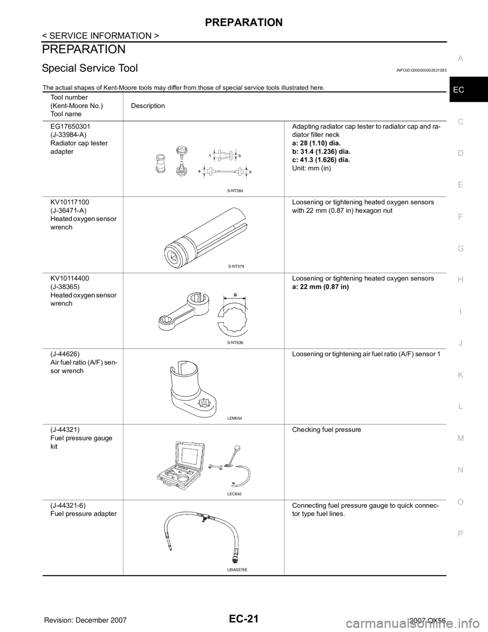
PREPARATION
Special Service ToolINFOID:0000000003531583
The actual shapes of Kent-Moore tools may differ from those of special service tools illustrated here.
Tool number
(Kent-Moore No.)
Tool nameDescription
EG17650301
(J-33984-A)
Radiator cap tester
adapterAdapting radiator cap tester to radiator cap and ra-
diator filler neck
a: 28 (1.10) dia.
b: 31.4 (1.236) dia.
c: 41.3 (1.626) dia.
Unit: mm (in)
KV10117100
(J-36471-A)
Heated oxygen sensor
wrenchLoosening or tightening heated oxygen sensors
with 22 mm (0.87 in) hexagon nut
KV10114400
(J-38365)
Heated oxygen sensor
wrenchLoosening or tightening heated oxygen sensors
a: 22 mm (0.87 in)
(J-44626)
Air fuel ratio (A/F) sen-
sor wrenchLoosening or tightening air fuel ratio (A/F) sensor 1
(J-44321)
Fuel pressure gauge
kitChecking fuel pressure
(J-44321-6)
Fuel pressure adapterConnecting fuel pressure gauge to quick connec-
tor type fuel lines.
S-NT564
S-NT379
S-NT636
LEM054
LEC642
LBIA0376E