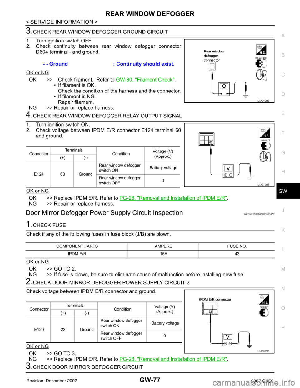
2007 INFINITI QX56 turn signal
[x] Cancel search: turn signalPage 2095 of 3061

GW-76
< SERVICE INFORMATION >
REAR WINDOW DEFOGGER
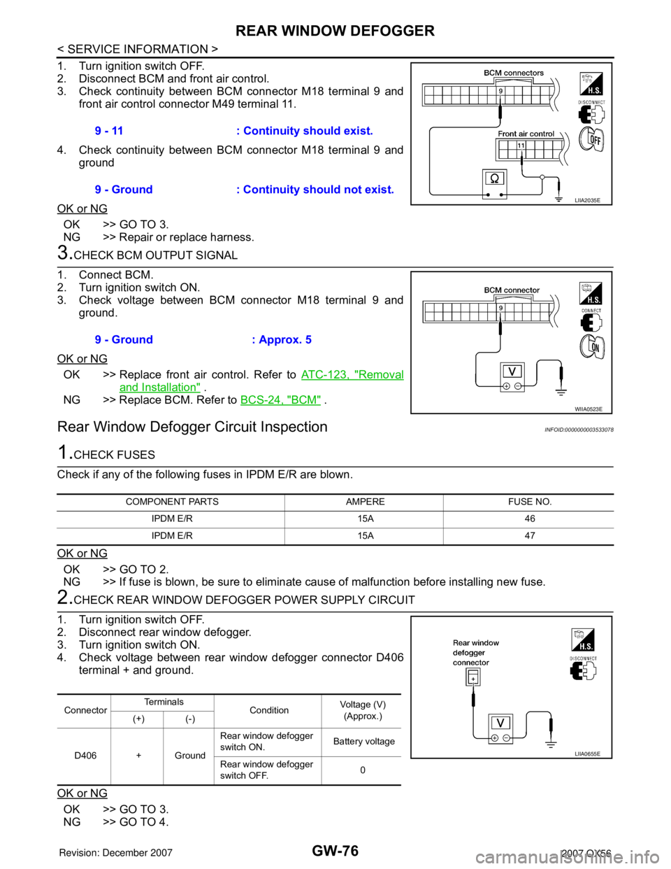
1. Turn ignition switch OFF.
2. Disconnect BCM and front air control.
3. Check continuity between BCM connector M18 terminal 9 and
front air control connector M49 terminal 11.
4. Check continuity between BCM connector M18 terminal 9 and
ground
OK or NG
OK >> GO TO 3.
NG >> Repair or replace harness.
3.CHECK BCM OUTPUT SIGNAL
1. Connect BCM.
2. Turn ignition switch ON.
3. Check voltage between BCM connector M18 terminal 9 and
ground.
OK or NG
OK >> Replace front air control. Refer to ATC-123, "Removal
and Installation" .
NG >> Replace BCM. Refer to BCS-24, "
BCM" .
Rear Window Defogger Circuit InspectionINFOID:0000000003533078
1.CHECK FUSES
Check if any of the following fuses in IPDM E/R are blown.
OK or NG
OK >> GO TO 2.
NG >> If fuse is blown, be sure to eliminate cause of malfunction before installing new fuse.
2.CHECK REAR WINDOW DEFOGGER POWER SUPPLY CIRCUIT
1. Turn ignition switch OFF.
2. Disconnect rear window defogger.
3. Turn ignition switch ON.
4. Check voltage between rear window defogger connector D406
terminal + and ground.
OK or NG
OK >> GO TO 3.
NG >> GO TO 4.9 - 11 : Continuity should exist.
9 - Ground : Continuity should not exist.
LIIA2035E
9 - Ground : Approx. 5
WIIA0523E
COMPONENT PARTS AMPERE FUSE NO.
IPDM E/R 15A 46
IPDM E/R 15A 47
ConnectorTe r m i n a l s
ConditionVoltage (V)
(Approx.)
(+) (-)
D406 + GroundRear window defogger
switch ON. Battery voltage
Rear window defogger
switch OFF.0
LIIA0655E
Page 2096 of 3061

REAR WINDOW DEFOGGER
GW-77
< SERVICE INFORMATION >
C
D
E
F
G
H
J
K
L
MA
B
GW
N
O
P
3.CHECK REAR WINDOW DEFOGGER GROUND CIRCUIT
1. Turn ignition switch OFF.
2. Check continuity between rear window defogger connector
D604 terminal - and ground.
OK or NG
OK >> Check filament. Refer to GW-80, "Filament Check".
• If filament is OK.
Check the condition of the harness and the connector.
• If filament is NG.
Repair filament.
NG >> Repair or replace harness.
4.CHECK REAR WINDOW DEFOGGER RELAY OUTPUT SIGNAL
1. Turn ignition switch ON.
2. Check voltage between IPDM E/R connector E124 terminal 60
and ground.
OK or NG
OK >> Replace IPDM E/R. Refer to PG-28, "Removal and Installation of IPDM E/R".
NG >> Repair or replace harness.
Door Mirror Defogger Power Supply Circuit InspectionINFOID:0000000003533079
1.CHECK FUSE
Check if any of the following fuses in fuse block (J/B) are blown.
OK or NG
OK >> GO TO 2.
NG >> If fuse is blown, be sure to eliminate cause of malfunction before installing new fuse.
2.CHECK DOOR MIRROR DEFOGGER POWER SUPPLY CIRCUIT 2
Check voltage between IPDM E/R connector and ground.
OK or NG
OK >> GO TO 3.
NG >> Replace IPDM E/R. Refer to PG-28, "
Removal and Installation of IPDM E/R".
3.CHECK DOOR MIRROR DEFOGGER CIRCUIT- - Ground : Continuity should exist.
LIIA0409E
ConnectorTe r m i n a l s
ConditionVoltage (V)
(Approx.)
(+) (-)
E124 60 GroundRear window defogger
switch ON Battery voltage
Rear window defogger
switch OFF0
LIIA2190E
COMPONENT PARTS AMPERE FUSE NO.
IPDM E/R 15A 43
ConnectorTe r m i n a l s
ConditionVoltage (V)
(Approx.)
(+) (-)
E120 23 GroundRear window defogger
switch ON Battery voltage
Rear window defogger
switch OFF0
LIIA0977E
Page 2112 of 3061

IDX-8
ALPHABETICAL INDEX
Three way catalyst ............................................ EM-21
Three way catalyst function (Bank 1) ............... EC-376
Three way catalyst function (Bank 2) ............... EC-376
Three way catalyst precautions ............................ GI-5
Throttle control motor ....................................... EC-601
Throttle control motor relay .............................. EC-589
Throttle position sensor (TPS) .. EC-224, EC-343, EC-
514, EC-516, EC-621
Throttle valve closed position learning ............... EC-80
Tie-rod ............................................................... PS-15
Timing chain ..................................................... EM-37
Tire rotation ....................................................... MA-28
Tire size .............................................................. GI-51
Torque converter installation AT-239, AT-240, AT-243,
AT-244
Torque convertor clutch solenoid valve ... AT-114, AT-
116
Tow truck towing ................................................. GI-44
Towing point ....................................................... GI-45
TPS1 - Wiring diagram .................................... EC-345
TPS2 - Wiring diagram .................................... EC-226
TPS3 - Wiring diagram .................................... EC-623
Traction control system - Wiring diagram ....... BRC-16
Transfer control device ............. TF-75, TF-79, TF-138
Transfer control unit inspection table ................. TF-35
Transfer dropping resistor .................................. TF-89
Transfer fluid temperature sensor TF-103, TF-154, TF-
167
Transfer motor .................................... TF-101, TF-142
Transfer motor relay ........................................ TF-101
Transfer oil replacement ................................... MA-24
Transfer serial number ........................................ GI-50
Transmission serial number ................................ GI-50
Tread-FR&RR (Dimensions) ............................... GI-51
Trim ..................................................................... EI-35
TRNSCV - Wiring diagram .................. BL-130, BL-146
Trouble diagnoses .............................................. GI-11
Turbine revolution sensor ................................ AT-105
TURN - Wiring diagram ...................................... LT-67
Turn signal lamp ................................................. LT-63
Two trip detection logic ...................................... EC-49
Two-pole lift ........................................................ GI-43
V
Vacuum hose (brake system) ............................ BR-20
Vacuum hose drawing (Engine control) ........... EC-106
Valve clearance ................................................ EM-55
Valve guide ....................................................... EM-69
Vanity mirror lamp ............................................. LT-110
VDC (vehicle dynamics control) ........................ BRC-7
VDC -Wiring diagram ...................................... BRC-16
Vehicle identification number .............................. GI-49
Vehicle recovery (freeing a stuck vehicle) .......... GI-45
Vehicle security (theft warning) system ............. BL-67
Vehicle speed sensor (VSS) ............................ EC-464
VEHSEC - Wiring diagram ................................. BL-71
VENT/V - Wiring diagram .................. EC-412, EC-419
VIN registration .................................................. EC-79
Viscosity number (SAE) .................................... MA-12
VSS A/T - Wiring diagram .................. AT-107, AT-109
W
W/ANT - Wiring diagram .................................... AV-59
Wait detection switch ......................................... TF-68
WARN - Wiring diagram ...................................... DI-29
Warning chime .................................................... DI-38
Warning lamps .................................................... DI-28
Washer, front ..................................................... WW-4
Washer, rear .................................................... WW-29
Water pump ...................................................... CO-19
Water temperature gauge ..................................... DI-5
Wheel alignment (front) ..................................... FSU-6
Wheel alignment (rear) ................................... RSU-25
Wheel bearing (front) ........................................ FAX-5
Wheel bearing (rear) ......................................... RAX-5
Wheel hub (rear) ............................................... RAX-5
Wheel size .......................................................... GI-51
Wheelbase (Dimensions) .................................... GI-51
Width (Dimensions) ............................................. GI-51
WINDOW - Wiring diagram .............................. GW-22
Window, door ...................................... GW-62, GW-65
Windshield ....................................................... GW-11
WIP/R - Wiring diagram ................................... WW-33
WIPER - Wiring diagram .................................... WW-8
Wiper, front ........................................................ WW-4
Wiper, rear ....................................................... WW-29
Wiring Diagram (Cell code) list ......................... PG-62
Wiring diagrams .................................................. GI-15
WT-T/WARN - Wiring diagram .......................... WT-11
Page 2138 of 3061
![INFINITI QX56 2007 Factory Service Manual TROUBLE DIAGNOSIS
LAN-7
< SERVICE INFORMATION >[CAN FUNDAMENTAL]
C
D
E
F
G
H
I
J
L
MA
B
LAN
N
O
P
TROUBLE DIAGNOSIS
Condition of Error DetectionINFOID:0000000003533611
“U1000” or “U1001” is in INFINITI QX56 2007 Factory Service Manual TROUBLE DIAGNOSIS
LAN-7
< SERVICE INFORMATION >[CAN FUNDAMENTAL]
C
D
E
F
G
H
I
J
L
MA
B
LAN
N
O
P
TROUBLE DIAGNOSIS
Condition of Error DetectionINFOID:0000000003533611
“U1000” or “U1001” is in](/manual-img/42/57029/w960_57029-2137.png)
TROUBLE DIAGNOSIS
LAN-7
< SERVICE INFORMATION >[CAN FUNDAMENTAL]
C
D
E
F
G
H
I
J
L
MA
B
LAN
N
O
P
TROUBLE DIAGNOSIS
Condition of Error DetectionINFOID:0000000003533611
“U1000” or “U1001” is indicated on SELF-DIAG RESULTS on CONSULT-II if CAN communication signal is not
transmitted or received between units for 2 seconds or more.
CAN COMMUNICATION SYSTEM ERROR
• CAN communication line open (CAN-H, CAN-L, or both)
• CAN communication line short (ground, between CAN communication lines, other harnesses)
• Error of CAN communication control circuit of the unit connected to CAN communication line
WHEN INDICATED “U1000” OR “U1001” IS INDICATED EVEN THOUGH CAN COMMUNICATION
SYSTEM IS NORMAL
• CONSULT-II CONVERTER not connected: Error may be detected by the self-diagnosis when not using
CONSULT-II CONVERTER (Depending on the control unit which carries out CAN communication).
• Removal/installation of parts: Error may be detected when removing and installing CAN communication unit
and related parts while turning the ignition switch ON. (A DTC except for CAN communication may be
detected.)
• Fuse blown out (removed): CAN communication of the unit may cease.
• Voltage drop: Error may be detected if voltage drops due to discharged battery when turning the ignition
switch ON (Depending on the control unit which carries out CAN communication).
• Error may be detected if the power supply circuit of the control unit, which carries out CAN communication,
malfunctions (Depending on the control unit which carries out CAN communication).
• Error may be detected if reprogramming is not completed normally.
NOTE:
CAN communication system is normal if “U1000” or “U1001” is indicated on SELF-DIAG RESULTS of CON-
SULT-II under the above conditions. Erase the memory of the self-diagnosis of each unit.
Symptom When Error Occurs in CAN Communication SystemINFOID:0000000003533612
In CAN communication system, multiple units mutually transmit and receive signals. Each unit cannot transmit
and receive signals if any error occurs on CAN communication line. Under this condition, multiple control units
related to the root cause malfunction or go into fail-safe mode.
ERROR EXAMPLE
NOTE:
• Each vehicle differs in symptom of each unit under fail-safe mode and CAN communication line wiring.
• Refer to LAN-37, "
Abbreviation List" for the unit abbreviation.
Example: TCM branch line open circuit
SKIB8738E
Page 2139 of 3061
![INFINITI QX56 2007 Factory Service Manual LAN-8
< SERVICE INFORMATION >[CAN FUNDAMENTAL]
TROUBLE DIAGNOSIS
Example: Data link connector branch line open circuit
NOTE:
• When data link connector branch line is open, transmission and receptio INFINITI QX56 2007 Factory Service Manual LAN-8
< SERVICE INFORMATION >[CAN FUNDAMENTAL]
TROUBLE DIAGNOSIS
Example: Data link connector branch line open circuit
NOTE:
• When data link connector branch line is open, transmission and receptio](/manual-img/42/57029/w960_57029-2138.png)
LAN-8
< SERVICE INFORMATION >[CAN FUNDAMENTAL]
TROUBLE DIAGNOSIS
Example: Data link connector branch line open circuit
NOTE:
• When data link connector branch line is open, transmission and reception of CAN communication signals is
not affected. Therefore, no symptoms occur. However, be sure to repair malfunctioning circuit.
• When data link connector branch line is open, the screen-display of the CONSULT-II “SELECT SYSTEM”
screen may be the same as when the CAN communication line has short-circuit. However, symptoms differ
depending on the case. See below chart for the differences.
Unit name Symptom
ECM Engine torque limiting is affected, and shift harshness increases.
BCM Reverse warning chime does not sound.
EPS control unit Normal operation.
Combination meter• Shift position indicator and OD OFF indicator turn OFF.
• Warning lamps turn ON.
ABS actuator and electric unit (control unit) Normal operation.
TCM No impact on operation.
IPDM E/R Normal operation.
SKIB8739E
Unit name Symptom
ECM
Normal operation. BCM
EPS control unit
Combination meter
ABS actuator and electric unit (control unit)
TCM
IPDM E/R
SELECT SYSTEM
(CONSULT-II)Difference of symptom
Data link connector branch line open circuit
All Diag on CAN units are not
indicated.Normal operation.
CAN-H, CAN-L harness short-circuitMost the units which are connected to the CAN com-
munication system enter fail-safe mode or are deac-
tivated.
Page 2141 of 3061
![INFINITI QX56 2007 Factory Service Manual LAN-10
< SERVICE INFORMATION >[CAN FUNDAMENTAL]
TROUBLE DIAGNOSIS
Self-Diagnosis
INFOID:0000000003533613
CAN Diagnostic Support MonitorINFOID:0000000003533614
CONSULT-II and CAN diagnostic support mon INFINITI QX56 2007 Factory Service Manual LAN-10
< SERVICE INFORMATION >[CAN FUNDAMENTAL]
TROUBLE DIAGNOSIS
Self-Diagnosis
INFOID:0000000003533613
CAN Diagnostic Support MonitorINFOID:0000000003533614
CONSULT-II and CAN diagnostic support mon](/manual-img/42/57029/w960_57029-2140.png)
LAN-10
< SERVICE INFORMATION >[CAN FUNDAMENTAL]
TROUBLE DIAGNOSIS
Self-Diagnosis
INFOID:0000000003533613
CAN Diagnostic Support MonitorINFOID:0000000003533614
CONSULT-II and CAN diagnostic support monitor (on-board diagnosis function) are used for detecting root
cause.
MONITOR ITEM (CONSULT-II)
Unit name Symptom
ECM• Engine torque limiting is affected, and shift harshness increases.
• Engine speed drops.
BCM• Reverse warning chime does not sound.
• The front wiper moves under continuous operation mode even though the front
wiper switch being in the intermittent position.
• The room lamp does not turn ON.
• The engine does not start (if an error or malfunction occurs while turning the igni-
tion switch is OFF.)
• The steering lock does not release (if an error or malfunction occurs while turning
the ignition switch is OFF.)
EPS control unit The steering effort increases.
Combination meter• The tachometer and the speedometer do not move.
• Warning lamps turn ON.
• Indicator lamps do not turn ON.
ABS actuator and electric unit (control unit) Normal operation.
TCM No impact on operation.
IPDM E/RWhen the ignition switch is ON,
• The headlamps (Lo) turn ON.
• The cooling fan continues to rotate.
DTCSelf-diagnosis item
(CONSULT-II indication)DTC detection condition Inspection/Action
U1000 CAN COMM CIRCUITWhen ECM is not transmitting or receiving CAN
communication signal of OBD (emission-related
diagnosis) for 2 seconds or more.
Refer to LAN-13
. When a control unit (except for ECM) is not
transmitting or receiving CAN communication
signal for 2 seconds or more.
U1001 CAN COMM CIRCUITWhen ECM is not transmitting or receiving CAN
communication signal other than OBD (emis-
sion-related diagnosis) for 2 seconds or more.
U1002 SYSTEM COMMWhen a control unit is not transmitting or receiv-
ing CAN communication signal for 2 seconds or
less.Start the inspection. Re-
fer to the applicable sec-
tion of the indicated
control unit.
U1010 CONTROL UNIT [CAN]When an error is detected during the initial diag-
nosis for CAN controller of each control unit.Replace the control unit
indicating “U1010”.
Page 2162 of 3061
![INFINITI QX56 2007 Factory Service Manual TROUBLE DIAGNOSES WORK FLOW
LAN-31
< SERVICE INFORMATION >[CAN FUNDAMENTAL]
C
D
E
F
G
H
I
J
L
MA
B
LAN
N
O
P
b. Reception item of “ABS”: Assume that the unit could not receive the signal from ECM. INFINITI QX56 2007 Factory Service Manual TROUBLE DIAGNOSES WORK FLOW
LAN-31
< SERVICE INFORMATION >[CAN FUNDAMENTAL]
C
D
E
F
G
H
I
J
L
MA
B
LAN
N
O
P
b. Reception item of “ABS”: Assume that the unit could not receive the signal from ECM.](/manual-img/42/57029/w960_57029-2161.png)
TROUBLE DIAGNOSES WORK FLOW
LAN-31
< SERVICE INFORMATION >[CAN FUNDAMENTAL]
C
D
E
F
G
H
I
J
L
MA
B
LAN
N
O
P
b. Reception item of “ABS”: Assume that the unit could not receive the signal from ECM. Draw a line
between ABS and ECM (line 3-b in the figure).
4. Search for the possible cause using CAN communication signal chart using information from the interview
with the customer.
NOTE:
For the details of CAN communication signal, refer to LAN-44, "
CAN Communication Signal Chart".
a. ABS warning lamp turned ON and speedometer did not move: This means that “ABS warning lamp signal”
and “Vehicle speed signal” could not communicate between M&A and ABS (4-a in the figure).
SKIB8733E
Page 2163 of 3061
![INFINITI QX56 2007 Factory Service Manual LAN-32
< SERVICE INFORMATION >[CAN FUNDAMENTAL]
TROUBLE DIAGNOSES WORK FLOW
b. The tachometer moved normally: This means that “Engine speed signal” could communicate normally
between ECM and M&A ( INFINITI QX56 2007 Factory Service Manual LAN-32
< SERVICE INFORMATION >[CAN FUNDAMENTAL]
TROUBLE DIAGNOSES WORK FLOW
b. The tachometer moved normally: This means that “Engine speed signal” could communicate normally
between ECM and M&A (](/manual-img/42/57029/w960_57029-2162.png)
LAN-32
< SERVICE INFORMATION >[CAN FUNDAMENTAL]
TROUBLE DIAGNOSES WORK FLOW
b. The tachometer moved normally: This means that “Engine speed signal” could communicate normally
between ECM and M&A (4-b in the figure).
5. Fill out the diagnosis sheet based on information from step 4.
a. The ABS warning lamp turned ON and speedometer did not move: Assume that a possible cause is no
communication between M&A and ABS. Draw a line between M&A and ABS. (Line 5-a in the figure).
SKIB8895E