2007 INFINITI QX56 turn signal
[x] Cancel search: turn signalPage 2069 of 3061
GW-50
< SERVICE INFORMATION >
POWER WINDOW SYSTEM
Rear Power Window Motor LH Circuit Inspection
INFOID:0000000003533051
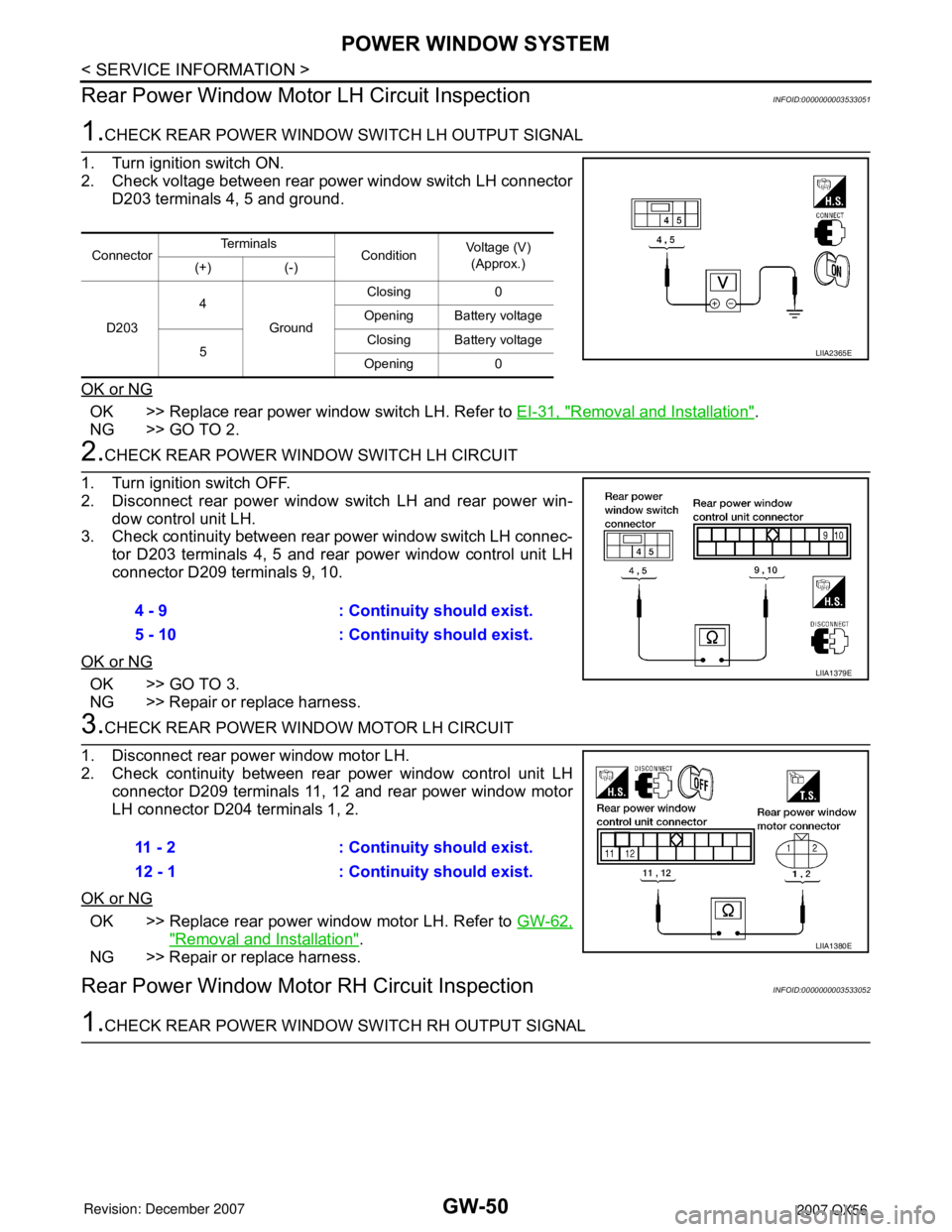
1.CHECK REAR POWER WINDOW SWITCH LH OUTPUT SIGNAL
1. Turn ignition switch ON.
2. Check voltage between rear power window switch LH connector
D203 terminals 4, 5 and ground.
OK or NG
OK >> Replace rear power window switch LH. Refer to EI-31, "Removal and Installation".
NG >> GO TO 2.
2.CHECK REAR POWER WINDOW SWITCH LH CIRCUIT
1. Turn ignition switch OFF.
2. Disconnect rear power window switch LH and rear power win-
dow control unit LH.
3. Check continuity between rear power window switch LH connec-
tor D203 terminals 4, 5 and rear power window control unit LH
connector D209 terminals 9, 10.
OK or NG
OK >> GO TO 3.
NG >> Repair or replace harness.
3.CHECK REAR POWER WINDOW MOTOR LH CIRCUIT
1. Disconnect rear power window motor LH.
2. Check continuity between rear power window control unit LH
connector D209 terminals 11, 12 and rear power window motor
LH connector D204 terminals 1, 2.
OK or NG
OK >> Replace rear power window motor LH. Refer to GW-62,
"Removal and Installation".
NG >> Repair or replace harness.
Rear Power Window Motor RH Circuit InspectionINFOID:0000000003533052
1.CHECK REAR POWER WINDOW SWITCH RH OUTPUT SIGNAL
ConnectorTe r m i n a l s
ConditionVoltage (V)
(Approx.)
(+) (-)
D2034
GroundClosing 0
Opening Battery voltage
5Closing Battery voltage
Opening 0
LIIA2365E
4 - 9 : Continuity should exist.
5 - 10 : Continuity should exist.
LIIA1379E
11 - 2 : Continuity should exist.
12 - 1 : Continuity should exist.
LIIA1380E
Page 2070 of 3061
POWER WINDOW SYSTEM
GW-51
< SERVICE INFORMATION >
C
D
E
F
G
H
J
K
L
MA
B
GW
N
O
P
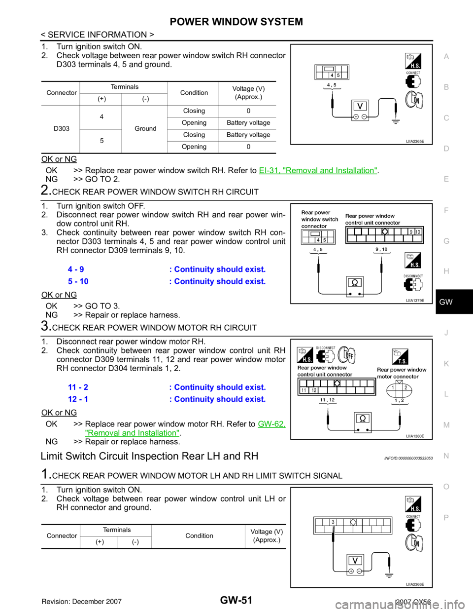
1. Turn ignition switch ON.
2. Check voltage between rear power window switch RH connector
D303 terminals 4, 5 and ground.
OK or NG
OK >> Replace rear power window switch RH. Refer to EI-31, "Removal and Installation".
NG >> GO TO 2.
2.CHECK REAR POWER WINDOW SWITCH RH CIRCUIT
1. Turn ignition switch OFF.
2. Disconnect rear power window switch RH and rear power win-
dow control unit RH.
3. Check continuity between rear power window switch RH con-
nector D303 terminals 4, 5 and rear power window control unit
RH connector D309 terminals 9, 10.
OK or NG
OK >> GO TO 3.
NG >> Repair or replace harness.
3.CHECK REAR POWER WINDOW MOTOR RH CIRCUIT
1. Disconnect rear power window motor RH.
2. Check continuity between rear power window control unit RH
connector D309 terminals 11, 12 and rear power window motor
RH connector D304 terminals 1, 2.
OK or NG
OK >> Replace rear power window motor RH. Refer to GW-62,
"Removal and Installation".
NG >> Repair or replace harness.
Limit Switch Circuit Inspection Rear LH and RHINFOID:0000000003533053
1.CHECK REAR POWER WINDOW MOTOR LH AND RH LIMIT SWITCH SIGNAL
1. Turn ignition switch ON.
2. Check voltage between rear power window control unit LH or
RH connector and ground.
ConnectorTe r m i n a l s
ConditionVoltage (V)
(Approx.)
(+) (-)
D3034
GroundClosing 0
Opening Battery voltage
5Closing Battery voltage
Opening 0
LIIA2365E
4 - 9 : Continuity should exist.
5 - 10 : Continuity should exist.
LIIA1379E
11 - 2 : Continuity should exist.
12 - 1 : Continuity should exist.
LIIA1380E
ConnectorTe r m i n a l s
Condition Voltage (V)
(Approx.)
(+) (-)
LIIA2366E
Page 2071 of 3061
GW-52
< SERVICE INFORMATION >
POWER WINDOW SYSTEM
OK or NG
OK >> Limit switch circuit is OK.
NG >> GO TO 2.
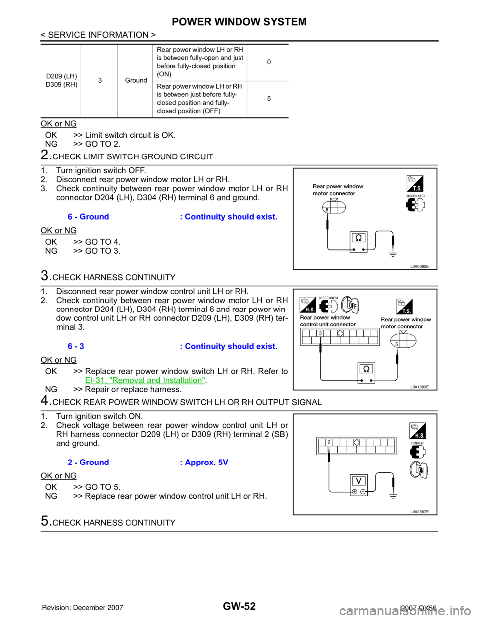
2.CHECK LIMIT SWITCH GROUND CIRCUIT
1. Turn ignition switch OFF.
2. Disconnect rear power window motor LH or RH.
3. Check continuity between rear power window motor LH or RH
connector D204 (LH), D304 (RH) terminal 6 and ground.
OK or NG
OK >> GO TO 4.
NG >> GO TO 3.
3.CHECK HARNESS CONTINUITY
1. Disconnect rear power window control unit LH or RH.
2. Check continuity between rear power window motor LH or RH
connector D204 (LH), D304 (RH) terminal 6 and rear power win-
dow control unit LH or RH connector D209 (LH), D309 (RH) ter-
minal 3.
OK or NG
OK >> Replace rear power window switch LH or RH. Refer to
EI-31, "
Removal and Installation".
NG >> Repair or replace harness.
4.CHECK REAR POWER WINDOW SWITCH LH OR RH OUTPUT SIGNAL
1. Turn ignition switch ON.
2. Check voltage between rear power window control unit LH or
RH harness connector D209 (LH) or D309 (RH) terminal 2 (SB)
and ground.
OK or NG
OK >> GO TO 5.
NG >> Replace rear power window control unit LH or RH.
5.CHECK HARNESS CONTINUITY
D209 (LH)
D309 (RH)3GroundRear power window LH or RH
is between fully-open and just
before fully-closed position
(ON)0
Rear power window LH or RH
is between just before fully-
closed position and fully-
closed position (OFF)5
6 - Ground : Continuity should exist.
LIIA0380E
6 - 3 : Continuity should exist.
LIIA1383E
2 - Ground : Approx. 5V
LIIA2367E
Page 2073 of 3061
GW-54
< SERVICE INFORMATION >
POWER WINDOW SYSTEM
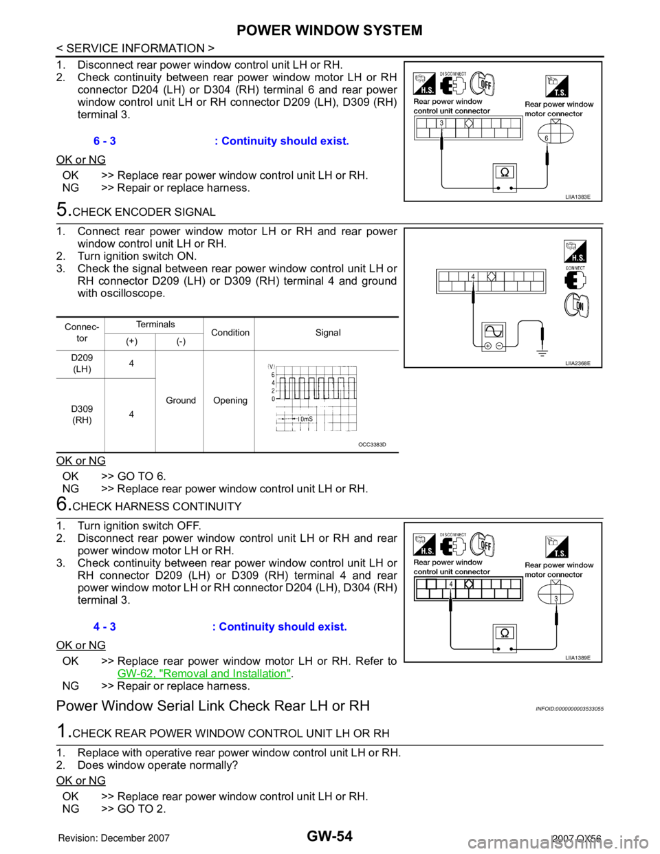
1. Disconnect rear power window control unit LH or RH.
2. Check continuity between rear power window motor LH or RH
connector D204 (LH) or D304 (RH) terminal 6 and rear power
window control unit LH or RH connector D209 (LH), D309 (RH)
terminal 3.
OK or NG
OK >> Replace rear power window control unit LH or RH.
NG >> Repair or replace harness.
5.CHECK ENCODER SIGNAL
1. Connect rear power window motor LH or RH and rear power
window control unit LH or RH.
2. Turn ignition switch ON.
3. Check the signal between rear power window control unit LH or
RH connector D209 (LH) or D309 (RH) terminal 4 and ground
with oscilloscope.
OK or NG
OK >> GO TO 6.
NG >> Replace rear power window control unit LH or RH.
6.CHECK HARNESS CONTINUITY
1. Turn ignition switch OFF.
2. Disconnect rear power window control unit LH or RH and rear
power window motor LH or RH.
3. Check continuity between rear power window control unit LH or
RH connector D209 (LH) or D309 (RH) terminal 4 and rear
power window motor LH or RH connector D204 (LH), D304 (RH)
terminal 3.
OK or NG
OK >> Replace rear power window motor LH or RH. Refer to
GW-62, "
Removal and Installation".
NG >> Repair or replace harness.
Power Window Serial Link Check Rear LH or RHINFOID:0000000003533055
1.CHECK REAR POWER WINDOW CONTROL UNIT LH OR RH
1. Replace with operative rear power window control unit LH or RH.
2. Does window operate normally?
OK or NG
OK >> Replace rear power window control unit LH or RH.
NG >> GO TO 2.6 - 3 : Continuity should exist.
LIIA1383E
Connec-
torTe r m i n a l s
Condition Signal
(+) (-)
D209
(LH)4
Ground Opening
D309
(RH)4
LIIA2368E
OCC3383D
4 - 3 : Continuity should exist.
LIIA1389E
Page 2074 of 3061
POWER WINDOW SYSTEM
GW-55
< SERVICE INFORMATION >
C
D
E
F
G
H
J
K
L
MA
B
GW
N
O
P
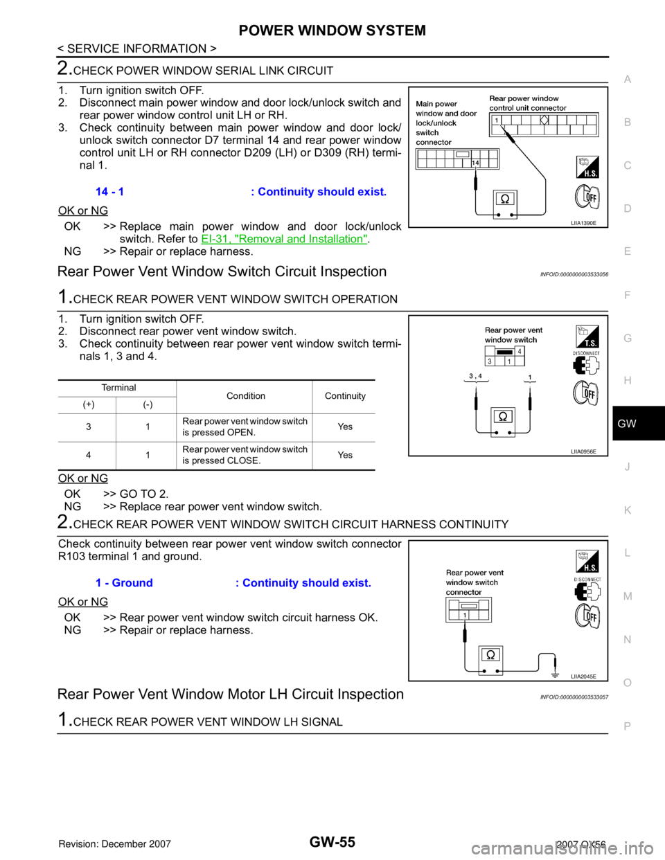
2.CHECK POWER WINDOW SERIAL LINK CIRCUIT
1. Turn ignition switch OFF.
2. Disconnect main power window and door lock/unlock switch and
rear power window control unit LH or RH.
3. Check continuity between main power window and door lock/
unlock switch connector D7 terminal 14 and rear power window
control unit LH or RH connector D209 (LH) or D309 (RH) termi-
nal 1.
OK or NG
OK >> Replace main power window and door lock/unlock
switch. Refer to EI-31, "
Removal and Installation".
NG >> Repair or replace harness.
Rear Power Vent Window Switch Circuit InspectionINFOID:0000000003533056
1.CHECK REAR POWER VENT WINDOW SWITCH OPERATION
1. Turn ignition switch OFF.
2. Disconnect rear power vent window switch.
3. Check continuity between rear power vent window switch termi-
nals 1, 3 and 4.
OK or NG
OK >> GO TO 2.
NG >> Replace rear power vent window switch.
2.CHECK REAR POWER VENT WINDOW SWITCH CIRCUIT HARNESS CONTINUITY
Check continuity between rear power vent window switch connector
R103 terminal 1 and ground.
OK or NG
OK >> Rear power vent window switch circuit harness OK.
NG >> Repair or replace harness.
Rear Power Vent Window Motor LH Circuit InspectionINFOID:0000000003533057
1.CHECK REAR POWER VENT WINDOW LH SIGNAL14 - 1 : Continuity should exist.
LIIA1390E
Te r m i n a l
Condition Continuity
(+) (-)
31Rear power vent window switch
is pressed OPEN.Ye s
41Rear power vent window switch
is pressed CLOSE.Ye s
LIIA0956E
1 - Ground : Continuity should exist.
LIIA2045E
Page 2075 of 3061
GW-56
< SERVICE INFORMATION >
POWER WINDOW SYSTEM
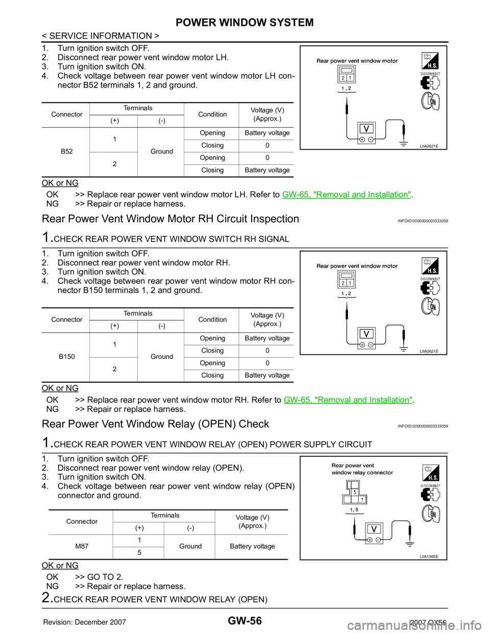
1. Turn ignition switch OFF.
2. Disconnect rear power vent window motor LH.
3. Turn ignition switch ON.
4. Check voltage between rear power vent window motor LH con-
nector B52 terminals 1, 2 and ground.
OK or NG
OK >> Replace rear power vent window motor LH. Refer to GW-65, "Removal and Installation".
NG >> Repair or replace harness.
Rear Power Vent Window Motor RH Circuit InspectionINFOID:0000000003533058
1.CHECK REAR POWER VENT WINDOW SWITCH RH SIGNAL
1. Turn ignition switch OFF.
2. Disconnect rear power vent window motor RH.
3. Turn ignition switch ON.
4. Check voltage between rear power vent window motor RH con-
nector B150 terminals 1, 2 and ground.
OK or NG
OK >> Replace rear power vent window motor RH. Refer to GW-65, "Removal and Installation".
NG >> Repair or replace harness.
Rear Power Vent Window Relay (OPEN) CheckINFOID:0000000003533059
1.CHECK REAR POWER VENT WINDOW RELAY (OPEN) POWER SUPPLY CIRCUIT
1. Turn ignition switch OFF.
2. Disconnect rear power vent window relay (OPEN).
3. Turn ignition switch ON.
4. Check voltage between rear power vent window relay (OPEN)
connector and ground.
OK or NG
OK >> GO TO 2.
NG >> Repair or replace harness.
2.CHECK REAR POWER VENT WINDOW RELAY (OPEN)
ConnectorTe r m i n a l s
ConditionVoltage (V)
(Approx.)
(+) (-)
B521
GroundOpening Battery voltage
Closing 0
2Opening 0
Closing Battery voltage
LIIA0621E
ConnectorTe r m i n a l s
ConditionVoltage (V)
(Approx.)
(+) (-)
B1501
GroundOpening Battery voltage
Closing 0
2Opening 0
Closing Battery voltage
LIIA0621E
ConnectorTe r m i n a l s
Voltage (V)
(Approx.)
(+) (-)
M871
Ground Battery voltage
5
LIIA1565E
Page 2088 of 3061

REAR WINDOW DEFOGGER
GW-69
< SERVICE INFORMATION >
C
D
E
F
G
H
J
K
L
MA
B
GW
N
O
P
• to IPDM E/R terminals 38 and 59
• through body grounds E9, E15 and E24.
When front air control (rear window defogger switch) is turned to ON, ground is supplied
• to BCM terminal 9
• through front air control terminal 11
• through front air control terminal 1
• through body grounds M57, M61 and M79.
Then rear window defogger switch is illuminated.
Then BCM recognizes that rear window defogger switch is turned to ON.
Then it sends rear window defogger switch signals to IPDM E/R and display control unit via CAN communica-
tion (CAN-H, CAN-L).
When display control unit receives rear window defogger switch signals, and displays on the screen.
When IPDM E/R receives rear window defogger switch signals, ground is supplied
• to rear window defogger relay (located in the IPDM E/R)
• through IPDM E/R terminal 38
• through IPDM E/R terminal 59
• through body grounds E9, E15 and E24
and then rear window defogger relay is energized.
With power and ground supplied, rear window defogger filaments heat and defog the rear window.
When rear window defogger relay is turned to ON, power is supplied
• through heated mirror relay (located in the IPDM E/R)
• through IPDM E/R terminal 23
• to door mirror defogger (LH and RH) terminal 10.
Door mirror defogger (LH and RH) is grounded through body grounds M57, M61 and M79.
With power and ground supplied, rear window defogger filaments heat and defog the rear window and door
mirror defogger filaments heat and defog the mirror.
CAN Communication System DescriptionINFOID:0000000003533068
Refer to LAN-4.
Page 2094 of 3061
REAR WINDOW DEFOGGER
GW-75
< SERVICE INFORMATION >
C
D
E
F
G
H
J
K
L
MA
B
GW
N
O
P
BCM Power Supply and Ground Circuit InspectionINFOID:0000000003533076
Refer to BCS-15, "BCM Power Supply and Ground Circuit Inspection".
Rear Window Defogger Switch Circuit InspectionINFOID:0000000003533077
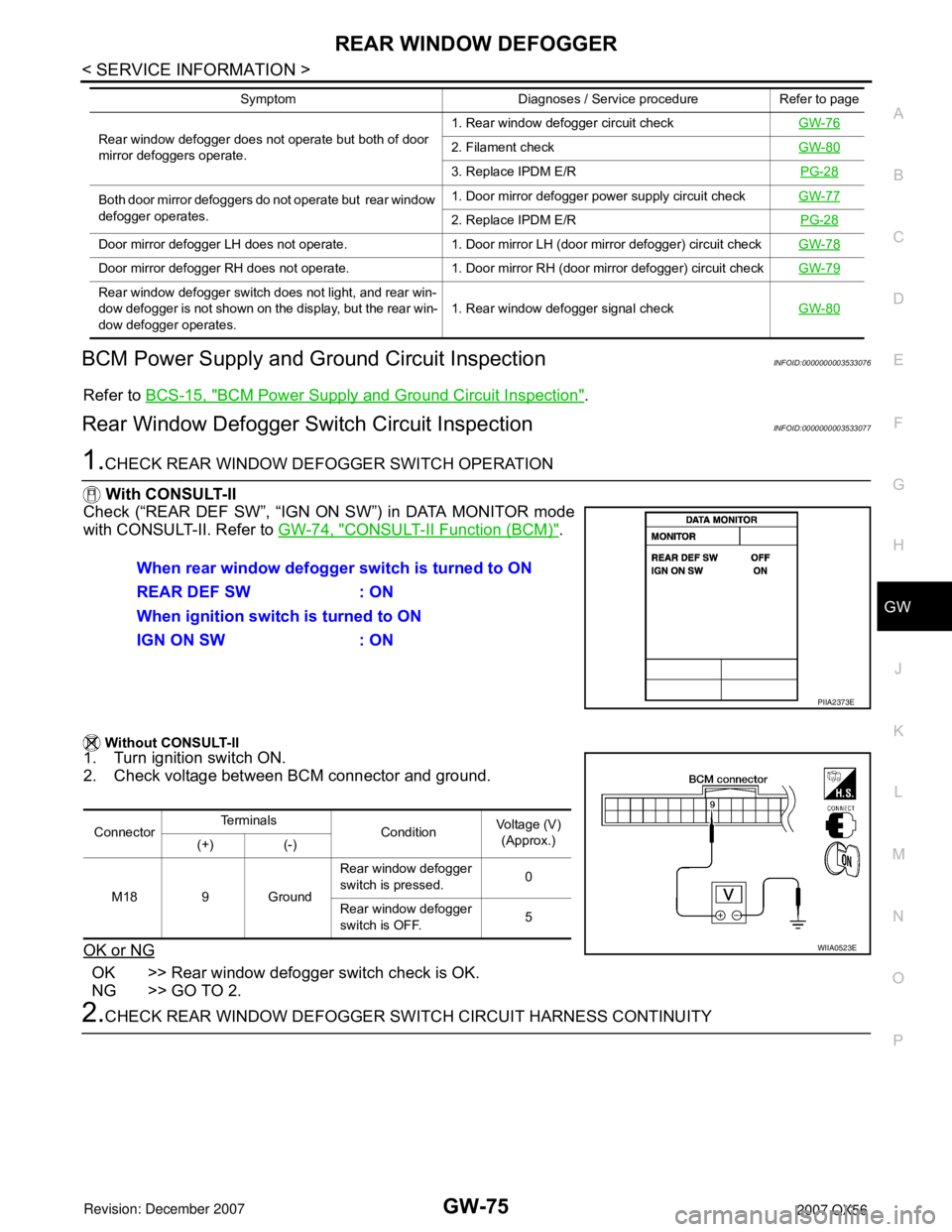
1.CHECK REAR WINDOW DEFOGGER SWITCH OPERATION
With CONSULT-II
Check (“REAR DEF SW”, “IGN ON SW”) in DATA MONITOR mode
with CONSULT-II. Refer to GW-74, "
CONSULT-II Function (BCM)".
Without CONSULT-II
1. Turn ignition switch ON.
2. Check voltage between BCM connector and ground.
OK or NG
OK >> Rear window defogger switch check is OK.
NG >> GO TO 2.
2.CHECK REAR WINDOW DEFOGGER SWITCH CIRCUIT HARNESS CONTINUITY
Rear window defogger does not operate but both of door
mirror defoggers operate.1. Rear window defogger circuit checkGW-762. Filament checkGW-80
3. Replace IPDM E/RPG-28
Both door mirror defoggers do not operate but rear window
defogger operates.1. Door mirror defogger power supply circuit checkGW-77
2. Replace IPDM E/RPG-28
Door mirror defogger LH does not operate. 1. Door mirror LH (door mirror defogger) circuit checkGW-78
Door mirror defogger RH does not operate. 1. Door mirror RH (door mirror defogger) circuit checkGW-79
Rear window defogger switch does not light, and rear win-
dow defogger is not shown on the display, but the rear win-
dow defogger operates. 1. Rear window defogger signal checkGW-80
Symptom Diagnoses / Service procedure Refer to page
When rear window defogger switch is turned to ON
REAR DEF SW : ON
When ignition switch is turned to ON
IGN ON SW : ON
PIIA2373E
ConnectorTe r m i n a l s
ConditionVoltage (V)
(Approx.)
(+) (-)
M18 9 GroundRear window defogger
switch is pressed.0
Rear window defogger
switch is OFF.5
WIIA0523E