Page 1685 of 3061
EC-602
< SERVICE INFORMATION >
ASCD BRAKE SWITCH
>> Repair open circuit or short to ground or short to power in harness or connectors.
9.CHECK STOP LAMP SWITCH INPUT SIGNAL CIRCUIT FOR OPEN AND SHORT
1. Disconnect ECM harness connector.
2. Check harness continuity between ECM terminal 101 and stop lamp switch terminal 4.
Refer to Wiring Diagram.
3. Also check harness for short to ground and short to power.
OK or NG
OK >> GO TO 10.
NG >> Repair open circuit or short to ground or short to power in harness or connectors.
10.CHECK STOP LAMP SWITCH
Refer to EC-602, "
Component Inspection" .
OK or NG
OK >> GO TO 11.
NG >> Replace stop lamp switch.
11 .CHECK INTERMITTENT INCIDENT
Refer to EC-138
.
>>INSPECTION END
Component InspectionINFOID:0000000003532152
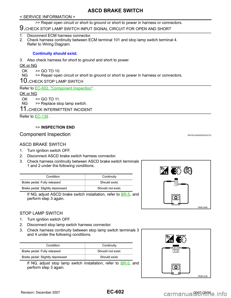
ASCD BRAKE SWITCH
1. Turn ignition switch OFF.
2. Disconnect ASCD brake switch harness connector.
3. Check harness continuity between ASCD brake switch terminals
1 and 2 under the following conditions.
If NG, adjust ASCD brake switch installation, refer to BR-5
, and
perform step 3 again.
STOP LAMP SWITCH
1. Turn ignition switch OFF.
2. Disconnect stop lamp switch harness connector.
3. Check harness continuity between stop lamp switch terminals 3
and 4 under the following conditions.
If NG, adjust stop lamp switch installation, refer to BR-5
, and
perform step 3 again.Continuity should exist.
Condition Continuity
Brake pedal: Fully released Should exist.
Brake pedal: Slightly depressed Should not exist.
PBIB1536E
Condition Continuity
Brake pedal: Fully released Should not exist.
Brake pedal: Slightly depressed Should exist.
PBIB2103E
Page 1689 of 3061
EC-606
< SERVICE INFORMATION >
ELECTRICAL LOAD SIGNAL
ELECTRICAL LOAD SIGNAL
DescriptionINFOID:0000000003532157
The electrical load signal (Headlamp switch signal, rear window defogger switch signal, etc.) is transferred
through the CAN communication line from BCM to ECM via IPDM E/R.
CONSULT-II Reference Value in Data Monitor ModeINFOID:0000000003532158
Specification data are reference values.
Diagnosis ProcedureINFOID:0000000003532159
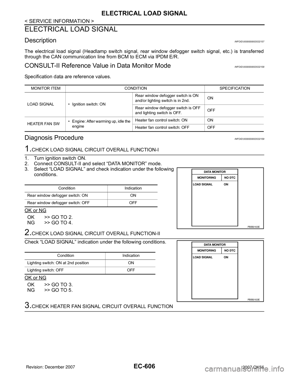
1.CHECK LOAD SIGNAL CIRCUIT OVERALL FUNCTION-I
1. Turn ignition switch ON.
2. Connect CONSULT-II and select “DATA MONITOR” mode.
3. Select “LOAD SIGNAL” and check indication under the following
conditions.
OK or NG
OK >> GO TO 2.
NG >> GO TO 4.
2.CHECK LOAD SIGNAL CIRCUIT OVERALL FUNCTION-II
Check “LOAD SIGNAL” indication under the following conditions.
OK or NG
OK >> GO TO 3.
NG >> GO TO 5.
3.CHECK HEATER FAN SIGNAL CIRCUIT OVERALL FUNCTION
MONITOR ITEM CONDITION SPECIFICATION
LOAD SIGNAL • Ignition switch: ONRear window defogger switch is ON
and/or lighting switch is in 2nd.ON
Rear window defogger switch is OFF
and lighting switch is OFF.OFF
HEATER FAN SW• Engine: After warming up, idle the
engineHeater fan control switch: ON ON
Heater fan control switch: OFF OFF
Condition Indication
Rear window defogger switch: ON ON
Rear window defogger switch: OFF OFF
PBIB0103E
Condition Indication
Lighting switch: ON at 2nd position ON
Lighting switch: OFF OFF
PBIB0103E
Page 1693 of 3061

EC-610
< SERVICE INFORMATION >
FUEL INJECTOR
Do not use ECM ground terminals when measuring input/output voltage. Doing so may result in dam-
age to the ECM's transistor. Use a ground other than ECM terminals, such as the ground.
: Average voltage for pulse signal (Actual pulse signal can be confirmed by oscilloscope.)
Diagnosis ProcedureINFOID:0000000003532163
1.INSPECTION START
Turn ignition switch to START.
Is any cylinder ignited?
Ye s o r N o
Ye s > > G O T O 2 .
No >> GO TO 3.
2.CHECK OVERALL FUNCTION
With CONSULT-II
1. Start engine.
2. Perform “POWER BALANCE” in “ACTIVE TEST” mode with
CONSULT-II.
3. Make sure that each circuit produces a momentary engine
speed drop.
Without CONSULT-II
1. Start engine.
TER-
MI-
NAL
NO.WIRE
COLORITEM CONDITION DATA (DC Voltage)
21
22
23
40
41
42
44
63O/L
BR
GR/W
Y/G
P
L
O
GFuel injector No. 5
Fuel injector No. 3
Fuel injector No. 1
Fuel injector No. 6
Fuel injector No. 4
Fuel injector No. 2
Fuel injector No. 7
Fuel injector No. 8[Engine is running]
•Warm-up condition
• Idle speed
NOTE:
The pulse cycle changes depending on rpm at idle. BATTERY VOLTAGE
(11 - 14V)
[Engine is running]
•Warm-up condition
• Engine speed: 2,000 rpmBATTERY VOLTAGE
(11 - 14V)
PBIB0042E
PBIB0043E
PBIB0133E
Page 1694 of 3061
FUEL INJECTOR
EC-611
< SERVICE INFORMATION >
C
D
E
F
G
H
I
J
K
L
MA
EC
N
P O
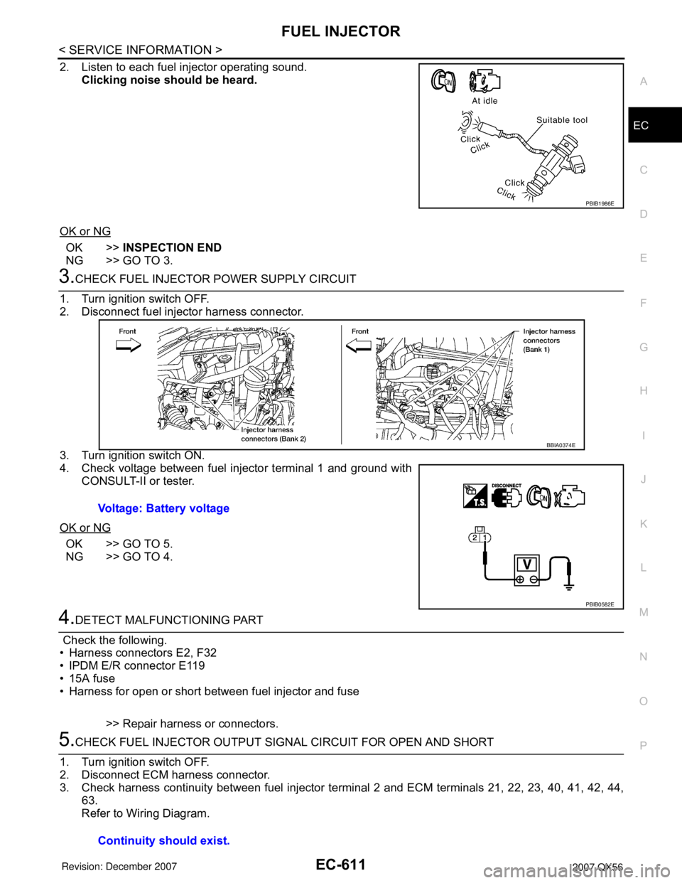
2. Listen to each fuel injector operating sound.
Clicking noise should be heard.
OK or NG
OK >>INSPECTION END
NG >> GO TO 3.
3.CHECK FUEL INJECTOR POWER SUPPLY CIRCUIT
1. Turn ignition switch OFF.
2. Disconnect fuel injector harness connector.
3. Turn ignition switch ON.
4. Check voltage between fuel injector terminal 1 and ground with
CONSULT-II or tester.
OK or NG
OK >> GO TO 5.
NG >> GO TO 4.
4.DETECT MALFUNCTIONING PART
Check the following.
• Harness connectors E2, F32
• IPDM E/R connector E119
• 15A fuse
• Harness for open or short between fuel injector and fuse
>> Repair harness or connectors.
5.CHECK FUEL INJECTOR OUTPUT SIGNAL CIRCUIT FOR OPEN AND SHORT
1. Turn ignition switch OFF.
2. Disconnect ECM harness connector.
3. Check harness continuity between fuel injector terminal 2 and ECM terminals 21, 22, 23, 40, 41, 42, 44,
63.
Refer to Wiring Diagram.
PBIB1986E
Voltage: Battery voltage
BBIA0374E
PBIB0582E
Continuity should exist.
Page 1696 of 3061
FUEL PUMP
EC-613
< SERVICE INFORMATION >
C
D
E
F
G
H
I
J
K
L
MA
EC
N
P O
FUEL PUMP
DescriptionINFOID:0000000003532166
SYSTEM DESCRIPTION
*: ECM determines the start signal status by the signals of engine speed and battery voltage.
The ECM activates the fuel pump for several seconds after the ignition switch is turned ON to improve engine
startability. If the ECM receives a engine speed signal from the camshaft position sensor (PHASE), it knows
that the engine is rotating, and causes the pump to operate. If the engine speed signal is not received when
the ignition switch is ON, the engine stalls. The ECM stops pump operation and prevents battery discharging,
thereby improving safety. The ECM does not directly drive the fuel pump. It controls the ON/OFF fuel pump
relay, which in turn controls the fuel pump.
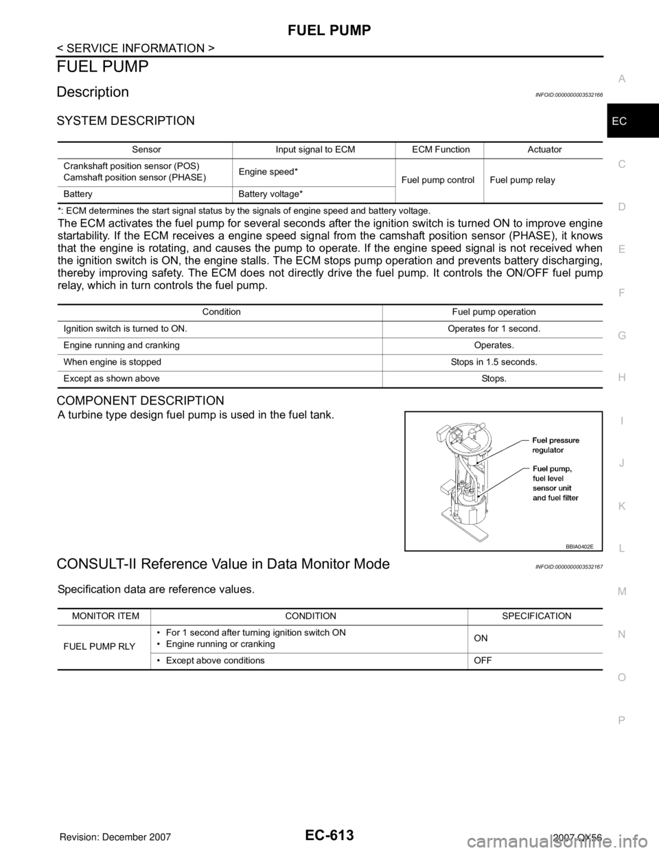
COMPONENT DESCRIPTION
A turbine type design fuel pump is used in the fuel tank.
CONSULT-II Reference Value in Data Monitor ModeINFOID:0000000003532167
Specification data are reference values.
Sensor Input signal to ECM ECM Function Actuator
Crankshaft position sensor (POS)
Camshaft position sensor (PHASE)Engine speed*
Fuel pump control Fuel pump relay
Battery Battery voltage*
Condition Fuel pump operation
Ignition switch is turned to ON. Operates for 1 second.
Engine running and crankingOperates.
When engine is stopped Stops in 1.5 seconds.
Except as shown aboveSto ps .
BBIA0402E
MONITOR ITEM CONDITION SPECIFICATION
FUEL PUMP RLY• For 1 second after turning ignition switch ON
• Engine running or crankingON
• Except above conditions OFF
Page 1702 of 3061
ICC BRAKE SWITCH
EC-619
< SERVICE INFORMATION >
C
D
E
F
G
H
I
J
K
L
MA
EC
N
P O
ICC BRAKE SWITCH
Component DescriptionINFOID:0000000003532172
When depress on the brake pedal, ICC brake switch is turned OFF
and stop lamp switch is turned ON. ECM detects the state of the
brake pedal by this input of two kinds (ON/OFF signal)
Refer to ACS-6
for the ICC function.
CONSULT-II Reference Value in Data Monitor ModeINFOID:0000000003532173
Specification data are reference values.
BBIA0470E
MONITOR ITEM CONDITION SPECIFICATION
BRAKE SW 1
(ICC brake switch)• Ignition switch: ONBrake pedal: Fully released ON
Brake pedal: Slightly depressed OFF
BRAKE SW 2
(Stop lamp switch)• Ignition switch: ONBrake pedal: Fully released OFF
Brake pedal: Slightly depressed ON
Page 1706 of 3061
ICC BRAKE SWITCH
EC-623
< SERVICE INFORMATION >
C
D
E
F
G
H
I
J
K
L
MA
EC
N
P O
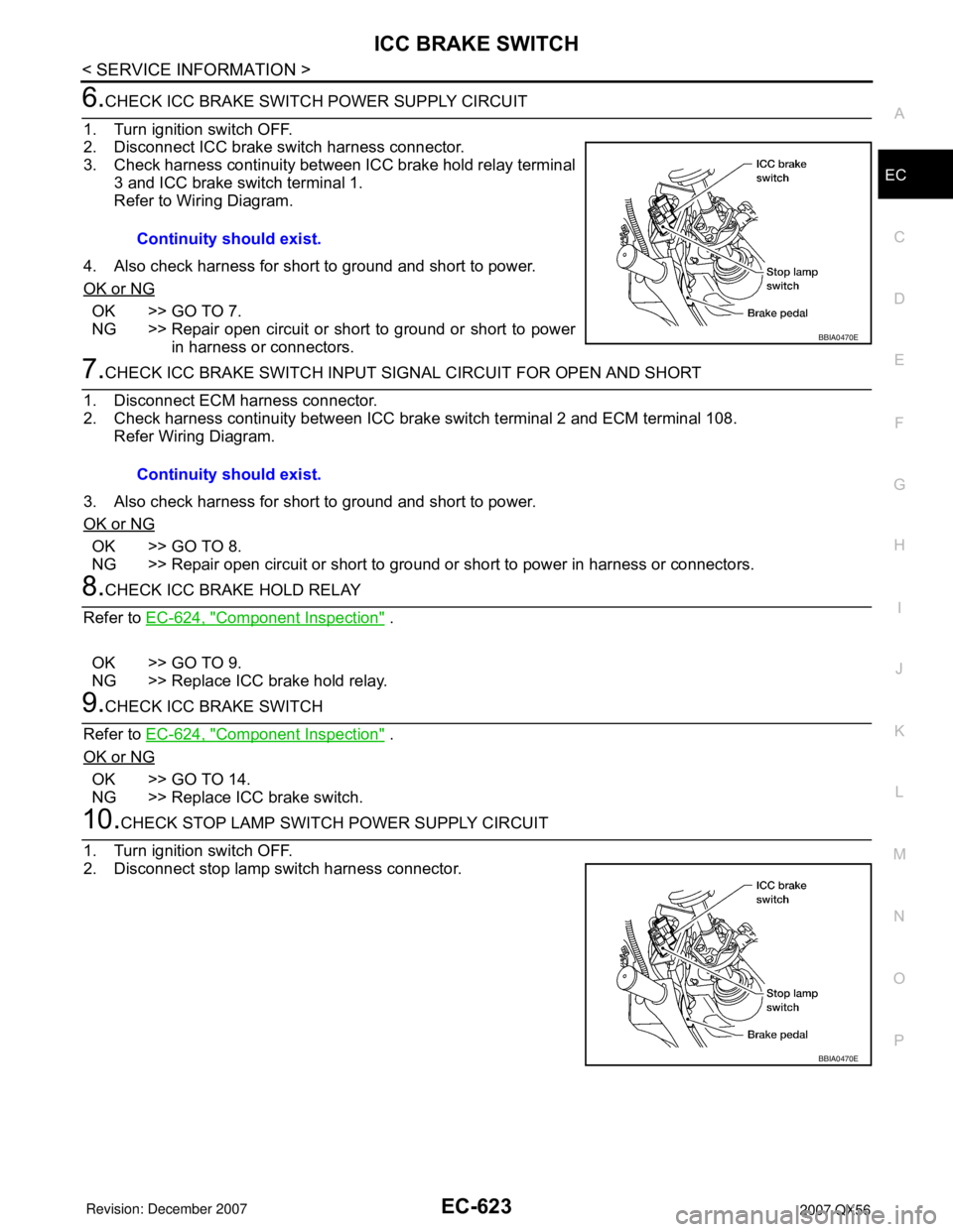
6.CHECK ICC BRAKE SWITCH POWER SUPPLY CIRCUIT
1. Turn ignition switch OFF.
2. Disconnect ICC brake switch harness connector.
3. Check harness continuity between ICC brake hold relay terminal
3 and ICC brake switch terminal 1.
Refer to Wiring Diagram.
4. Also check harness for short to ground and short to power.
OK or NG
OK >> GO TO 7.
NG >> Repair open circuit or short to ground or short to power
in harness or connectors.
7.CHECK ICC BRAKE SWITCH INPUT SIGNAL CIRCUIT FOR OPEN AND SHORT
1. Disconnect ECM harness connector.
2. Check harness continuity between ICC brake switch terminal 2 and ECM terminal 108.
Refer Wiring Diagram.
3. Also check harness for short to ground and short to power.
OK or NG
OK >> GO TO 8.
NG >> Repair open circuit or short to ground or short to power in harness or connectors.
8.CHECK ICC BRAKE HOLD RELAY
Refer to EC-624, "
Component Inspection" .
OK >> GO TO 9.
NG >> Replace ICC brake hold relay.
9.CHECK ICC BRAKE SWITCH
Refer to EC-624, "
Component Inspection" .
OK or NG
OK >> GO TO 14.
NG >> Replace ICC brake switch.
10.CHECK STOP LAMP SWITCH POWER SUPPLY CIRCUIT
1. Turn ignition switch OFF.
2. Disconnect stop lamp switch harness connector.Continuity should exist.
BBIA0470E
Continuity should exist.
BBIA0470E
Page 1707 of 3061
EC-624
< SERVICE INFORMATION >
ICC BRAKE SWITCH
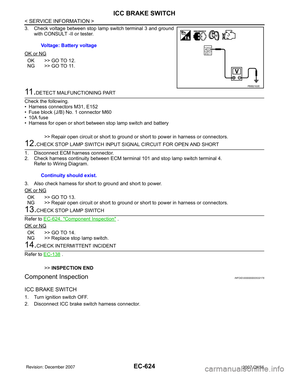
3. Check voltage between stop lamp switch terminal 3 and ground
with CONSULT -II or tester.
OK or NG
OK >> GO TO 12.
NG >> GO TO 11.
11 .DETECT MALFUNCTIONING PART
Check the following.
• Harness connectors M31, E152
• Fuse block (J/B) No. 1 connector M60
• 10A fuse
• Harness for open or short between stop lamp switch and battery
>> Repair open circuit or short to ground or short to power in harness or connectors.
12.CHECK STOP LAMP SWITCH INPUT SIGNAL CIRCUIT FOR OPEN AND SHORT
1. Disconnect ECM harness connector.
2. Check harness continuity between ECM terminal 101 and stop lamp switch terminal 4.
Refer to Wiring Diagram.
3. Also check harness for short to ground and short to power.
OK or NG
OK >> GO TO 13.
NG >> Repair open circuit or short to ground or short to power in harness or connectors.
13.CHECK STOP LAMP SWITCH
Refer to EC-624, "
Component Inspection" .
OK or NG
OK >> GO TO 14.
NG >> Replace stop lamp switch.
14.CHECK INTERMITTENT INCIDENT
Refer to EC-138
.
>>INSPECTION END
Component InspectionINFOID:0000000003532176
ICC BRAKE SWITCH
1. Turn ignition switch OFF.
2. Disconnect ICC brake switch harness connector.Voltage: Battery voltage
PBIB2102E
Continuity should exist.