2007 INFINITI QX56 battery
[x] Cancel search: batteryPage 2098 of 3061

REAR WINDOW DEFOGGER
GW-79
< SERVICE INFORMATION >
C
D
E
F
G
H
J
K
L
MA
B
GW
N
O
P
1. Turn ignition switch OFF.
2. Check continuity between door mirror LH connector D4 terminal
11 and ground.
OK or NG
OK >> GO TO 3.
NG >> Repair or replace harness.
3.CHECK DOOR MIRROR DEFOGGER
Check continuity between door mirror LH terminals 10 and 11.
OK or NG
OK >> Repair or replace harness.
NG >> Replace door mirror LH. Refer to GW-84, "
Door Mirror
Assembly".
Door Mirror RH (Door Mirror Defogger) Circuit InspectionINFOID:0000000003533081
1.CHECK DOOR MIRROR DEFOGGER POWER SUPPLY CIRCUIT
1. Turn ignition switch OFF.
2. Disconnect door mirror RH.
3. Turn ignition switch ON.
4. Check voltage between door mirror RH connector and ground.
OK or NG
OK >> GO TO 2.
NG >> Repair or replace harness.
2.CHECK DOOR MIRROR DEFOGGER GROUND CIRCUIT
1. Turn ignition switch OFF.
2. Check continuity between door mirror RH connector D107 termi-
nal 11 and ground.
OK or NG
OK >> GO TO 3.
NG >> Repair or replace harness.
3.CHECK DOOR MIRROR DEFOGGER 11 - Ground : Continuity should exist.
LIIA1458E
10 - 11 : Continuity should exist.
LIIA2725E
ConnectorTe r m i n a l s
ConditionVoltage (V)
(Approx.)
(+) (-)
D107 10 GroundRear window defogger
switch ON Battery voltage
Rear window defogger
switch OFF0
LIIA1456E
11 - Ground : Continuity should exist.
LIIA1458E
Page 2100 of 3061
REAR WINDOW DEFOGGER
GW-81
< SERVICE INFORMATION >
C
D
E
F
G
H
J
K
L
MA
B
GW
N
O
P
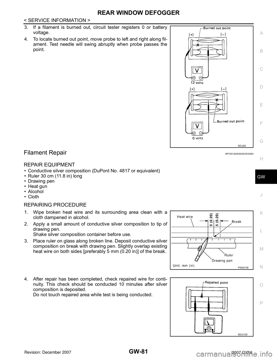
3. If a filament is burned out, circuit tester registers 0 or battery
voltage.
4. To locate burned out point, move probe to left and right along fil-
ament. Test needle will swing abruptly when probe passes the
point.
Filament RepairINFOID:0000000003533084
REPAIR EQUIPMENT
• Conductive silver composition (DuPont No. 4817 or equivalent)
• Ruler 30 cm (11.8 in) long
• Drawing pen
• Heat gun
• Alcohol
• Cloth
REPAIRING PROCEDURE
1. Wipe broken heat wire and its surrounding area clean with a
cloth dampened in alcohol.
2. Apply a small amount of conductive silver composition to tip of
drawing pen.
Shake silver composition container before use.
3. Place ruler on glass along broken line. Deposit conductive silver
composition on break with drawing pen. Slightly overlap existing
heat wire on both sides [preferably 5 mm (0.20 in)] of the break.
4. After repair has been completed, check repaired wire for conti-
nuity. This check should be conducted 10 minutes after silver
composition is deposited.
Do not touch repaired area while test is being conducted.
SEL265
PIIA0215E
SEL012D
Page 2106 of 3061
IDX-2
ALPHABETICAL INDEX
Numerics
2-4WD shift solenoid valve ..... TF-93
, TF-154, TF-167
4WD - Wiring diagram ....................................... TF-24
4WD shift switch ................................................ TF-65
4WD solenoid valve ................ TF-89, TF-154, TF-167
4WD system description .................................... TF-15
4WD system diagram ........................................ TF-19
A
A/C air flow ...................................................... ATC-30
A/C compressor clutch removal and installation .. ATC-
180
A/C compressor mounting ............................. ATC-179
A/C compressor precaution ............................. ATC-11
A/C compressor special service tool ................ ATC-14
A/C control operation (auto A/C) ...................... ATC-27
A/C diagnostic work flow (auto A/C) .............. ATC-133
A/C evaporator ............................................... ATC-186
A/C HFC134a (R134a) system identification ..... ATC-6
A/C HFC134a (R134a) system precaution ........ ATC-5
A/C HFC134a (R134a) system service procedure ATC-
175
A/C HFC134a (R134a) system service tools ... ATC-14
A/C HFC134a system service equipment precaution ...
ATC-11
A/C lubricant (R134a) ...................................... ATC-22
A/C lubrication oil ............................................. ATC-22
A/C operational check ....................... ATC-56, ATC-58
A/C self-diagnoses (auto A/C) ........ ATC-54, ATC-133
A/C service data specification ........................ ATC-193
A/C trouble diagnoses (auto A/C) .................... ATC-34
A/C, A - Wiring diagram ................................... ATC-42
A/T fluid checking ...................... AT-12, AT-51, MA-22
A/T fluid cooler cleaning .................................... AT-14
A/T fluid replacement ............................. AT-12, MA-24
A/T fluid temperature sensor ........................... AT-123
A/T IND - Wiring diagram .................................... DI-36
A/T indicator ........................................................ DI-36
A/T shift lock system ........................................ AT-216
A/T trouble diagnoses ........................................ AT-42
ABS - Wiring diagram ..................................... BRC-16
ABS (anti-lock brake system) ........................... BRC-7
Accelerator control system ............................... ACC-3
Accelerator pedal position (APP) sensor . EC-608, EC-
614, EC-628
Accelerator pedal released position learning ..... EC-80
AF1B1-Wiring diagram EC-242, EC-250, EC-258, EC-
267, EC-638
AF1B2-Wiring diagram EC-244, EC-252, EC-260, EC-
269, EC-640
AF1HB1-Wiring diagram .................................. EC-175
AF1HB2-Wiring diagram .................................. EC-177
Aiming adjustment .................................. LT-23, LT-61
Air bag .............................................................. SRS-3
Air bag precautions .............................................. AV-4
Air cleaner and air duct ..................................... EM-15
Air cleaner filter replacement ................ EM-16, MA-16
Air conditioner cut control ................................. EC-29
Air flow meter - See Mass air flow sensor EC-197, EC-
206
Air fuel ratio sensor 1 .. EC-239, EC-248, EC-256, EC-
264, EC-636
Air fuel ratio sensor 1 heater ........................... EC-174
Air mix. door motor .......................................... ATC-69
Ambient sensor ............................. ATC-138, ATC-149
Angular tightening application ............................. EM-4
Antenna .............................................................. AV-58
APPS1 - Wiring diagram ................................. EC-610
APPS2 - Wiring diagram ................................. EC-616
APPS3 - Wiring diagram ................................. EC-630
ASC/BS - Wiring diagram ............................... EC-574
ASC/SW - Wiring diagram .............................. EC-557
ASCBOF - Wiring diagram .............................. EC-648
ASCD ................................................................ EC-30
ASCD (automatic speed control device) ........... ACS-3
ASCD brake switch ........................... EC-572, EC-647
ASCD indicator lamp ....................................... EC-654
ASCD steering switch ..................................... EC-555
ASCIND - Wiring diagram ............................... EC-655
ATP switch ............................ TF-106, TF-109, TF-114
Audio .................................................................... AV-6
AUDIO - Wiring diagram .................................... AV-11
AUT/DP - Wiring diagram .................................. SE-16
Auto air conditioner - Wiring diagram .............. ATC-42
Auto anti-dazzling inside mirror ........... GW-69, GW-70
Autolamp ............................................................ LT-38
Automatic amplifier ......................................... ATC-59
Automatic drive positioner .................................. SE-11
Automatic transmission number .......................... GI-50
B
Back door ........................................................... BL-88
Back door trim ..................................................... EI-32
Back sonar .......................................................... DI-50
BACK/L - Wiring diagram ................................... LT-87
Back-up lamp ..................................................... LT-87
Ball joint (front) ................................................ FSU-15
Basic inspection ................................................ EC-73
Battery ................................................................. SC-4
Battery current sensor . EC-520, EC-527, EC-534, EC-
541
Battery/Starting/Charging System Tester SC-6, SC-12,
SC-20
BCM (Body control module) ................ BCS-3, AV-106
Block heater ...................................................... EM-78
Blower motor ................................... ATC-93, ATC-153
Body alignment ................................................ BL-164
Body component parts ..................................... BL-151
Body construction ............................................ BL-163
Body exterior paint color .................................. BL-150
Body mounting ................................................. BL-149
Body repair ....................................................... BL-150
Body sealing .................................................... BL-160
Bose speaker amp. .............................................. AV-8
Brake booster .................................................... BR-17
Page 2124 of 3061
IP-12
< SERVICE INFORMATION >
INSTRUMENT PANEL ASSEMBLY
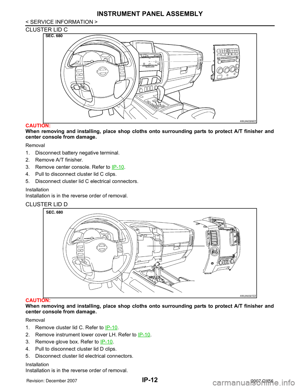
CLUSTER LID C
CAUTION:
When removing and installing, place shop cloths onto surrounding parts to protect A/T finisher and
center console from damage.
Removal
1. Disconnect battery negative terminal.
2. Remove A/T finisher.
3. Remove center console. Refer to IP-10
.
4. Pull to disconnect cluster lid C clips.
5. Disconnect cluster lid C electrical connectors.
Installation
Installation is in the reverse order of removal.
CLUSTER LID D
CAUTION:
When removing and installing, place shop cloths onto surrounding parts to protect A/T finisher and
center console from damage.
Removal
1. Remove cluster lid C. Refer to IP-10.
2. Remove instrument lower cover LH. Refer to IP-10
.
3. Remove glove box. Refer to IP-10
.
4. Pull to disconnect cluster lid D clips.
5. Disconnect cluster lid electrical connectors.
Installation
Installation is in the reverse order of removal.
AWJIA0326ZZ
AWJIA0327ZZ
Page 2125 of 3061
INSTRUMENT PANEL ASSEMBLY
IP-13
< SERVICE INFORMATION >
C
D
E
F
G
H
J
K
L
MA
B
IP
N
O
P
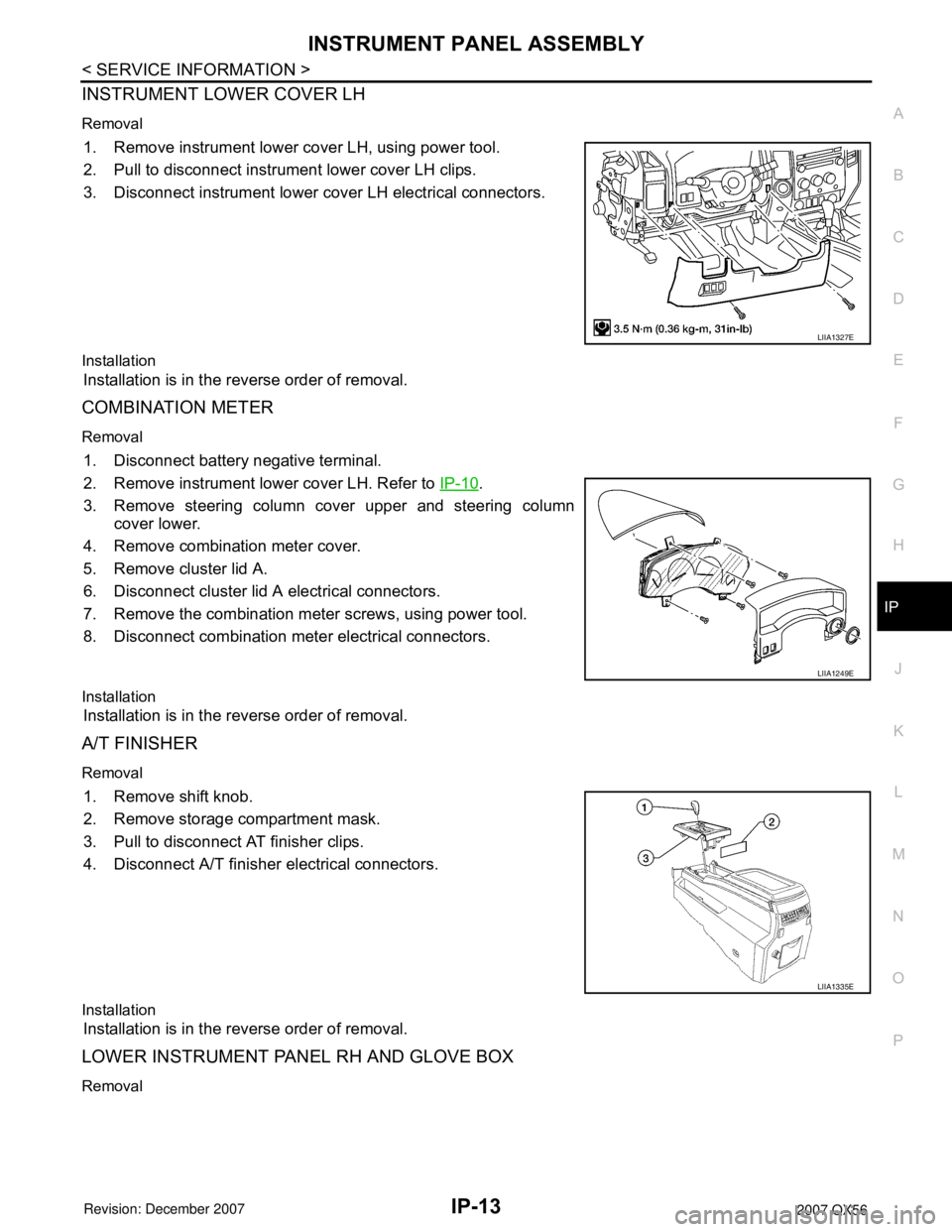
INSTRUMENT LOWER COVER LH
Removal
1. Remove instrument lower cover LH, using power tool.
2. Pull to disconnect instrument lower cover LH clips.
3. Disconnect instrument lower cover LH electrical connectors.
Installation
Installation is in the reverse order of removal.
COMBINATION METER
Removal
1. Disconnect battery negative terminal.
2. Remove instrument lower cover LH. Refer to IP-10
.
3. Remove steering column cover upper and steering column
cover lower.
4. Remove combination meter cover.
5. Remove cluster lid A.
6. Disconnect cluster lid A electrical connectors.
7. Remove the combination meter screws, using power tool.
8. Disconnect combination meter electrical connectors.
Installation
Installation is in the reverse order of removal.
A/T FINISHER
Removal
1. Remove shift knob.
2. Remove storage compartment mask.
3. Pull to disconnect AT finisher clips.
4. Disconnect A/T finisher electrical connectors.
Installation
Installation is in the reverse order of removal.
LOWER INSTRUMENT PANEL RH AND GLOVE BOX
Removal
LIIA1327E
LIIA1249E
LIIA1335E
Page 2126 of 3061
IP-14
< SERVICE INFORMATION >
INSTRUMENT PANEL ASSEMBLY
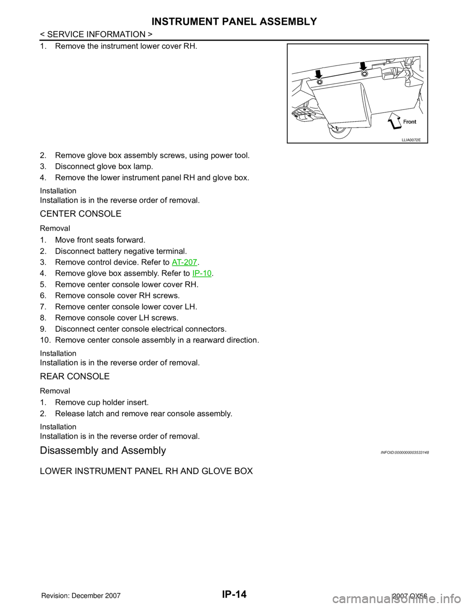
1. Remove the instrument lower cover RH.
2. Remove glove box assembly screws, using power tool.
3. Disconnect glove box lamp.
4. Remove the lower instrument panel RH and glove box.
Installation
Installation is in the reverse order of removal.
CENTER CONSOLE
Removal
1. Move front seats forward.
2. Disconnect battery negative terminal.
3. Remove control device. Refer to AT-207
.
4. Remove glove box assembly. Refer to IP-10
.
5. Remove center console lower cover RH.
6. Remove console cover RH screws.
7. Remove center console lower cover LH.
8. Remove console cover LH screws.
9. Disconnect center console electrical connectors.
10. Remove center console assembly in a rearward direction.
Installation
Installation is in the reverse order of removal.
REAR CONSOLE
Removal
1. Remove cup holder insert.
2. Release latch and remove rear console assembly.
Installation
Installation is in the reverse order of removal.
Disassembly and AssemblyINFOID:0000000003533148
LOWER INSTRUMENT PANEL RH AND GLOVE BOX
LLIA0072E
Page 2134 of 3061
![INFINITI QX56 2007 Factory Service Manual PRECAUTIONS
LAN-3
< SERVICE INFORMATION >[CAN FUNDAMENTAL]
C
D
E
F
G
H
I
J
L
MA
B
LAN
N
O
P
SERVICE INFORMATION
PRECAUTIONS
Precaution When Using CONSULT-IIINFOID:0000000003533606
Use CONSULT-II CONVE INFINITI QX56 2007 Factory Service Manual PRECAUTIONS
LAN-3
< SERVICE INFORMATION >[CAN FUNDAMENTAL]
C
D
E
F
G
H
I
J
L
MA
B
LAN
N
O
P
SERVICE INFORMATION
PRECAUTIONS
Precaution When Using CONSULT-IIINFOID:0000000003533606
Use CONSULT-II CONVE](/manual-img/42/57029/w960_57029-2133.png)
PRECAUTIONS
LAN-3
< SERVICE INFORMATION >[CAN FUNDAMENTAL]
C
D
E
F
G
H
I
J
L
MA
B
LAN
N
O
P
SERVICE INFORMATION
PRECAUTIONS
Precaution When Using CONSULT-IIINFOID:0000000003533606
Use CONSULT-II CONVERTER when connecting CONSULT-II to data link connector.
CAUTION:
CAN communication does not function properly if CONSULT-II is used without connecting CONSULT-II
CONVERTER.
Precaution for Trouble DiagnosisINFOID:0000000003533607
CAUTION:
• Never apply 7.0 V or more to the measurement terminal.
• Use a tester with open terminal voltage of 7.0 V or less.
• Turn the ignition switch OFF and disconnect the battery cable from the negative terminal when
checking the harness.
Precaution for Harness RepairINFOID:0000000003533608
• Solder the repaired area and wrap tape around the soldered area.
NOTE:
A fray of twisted lines must be within 110 mm (4.33 in).
• Bypass connection is never allowed at the repaired area.
NOTE:
Bypass connection may cause CAN communication error. The
spliced wire becomes separated and the characteristics of twisted
line are lost.
• Replace the applicable harness as an assembly if error is detected on the shield lines of CAN communica-
tion line.
SKIB8766E
SKIB8767E
Page 2138 of 3061
![INFINITI QX56 2007 Factory Service Manual TROUBLE DIAGNOSIS
LAN-7
< SERVICE INFORMATION >[CAN FUNDAMENTAL]
C
D
E
F
G
H
I
J
L
MA
B
LAN
N
O
P
TROUBLE DIAGNOSIS
Condition of Error DetectionINFOID:0000000003533611
“U1000” or “U1001” is in INFINITI QX56 2007 Factory Service Manual TROUBLE DIAGNOSIS
LAN-7
< SERVICE INFORMATION >[CAN FUNDAMENTAL]
C
D
E
F
G
H
I
J
L
MA
B
LAN
N
O
P
TROUBLE DIAGNOSIS
Condition of Error DetectionINFOID:0000000003533611
“U1000” or “U1001” is in](/manual-img/42/57029/w960_57029-2137.png)
TROUBLE DIAGNOSIS
LAN-7
< SERVICE INFORMATION >[CAN FUNDAMENTAL]
C
D
E
F
G
H
I
J
L
MA
B
LAN
N
O
P
TROUBLE DIAGNOSIS
Condition of Error DetectionINFOID:0000000003533611
“U1000” or “U1001” is indicated on SELF-DIAG RESULTS on CONSULT-II if CAN communication signal is not
transmitted or received between units for 2 seconds or more.
CAN COMMUNICATION SYSTEM ERROR
• CAN communication line open (CAN-H, CAN-L, or both)
• CAN communication line short (ground, between CAN communication lines, other harnesses)
• Error of CAN communication control circuit of the unit connected to CAN communication line
WHEN INDICATED “U1000” OR “U1001” IS INDICATED EVEN THOUGH CAN COMMUNICATION
SYSTEM IS NORMAL
• CONSULT-II CONVERTER not connected: Error may be detected by the self-diagnosis when not using
CONSULT-II CONVERTER (Depending on the control unit which carries out CAN communication).
• Removal/installation of parts: Error may be detected when removing and installing CAN communication unit
and related parts while turning the ignition switch ON. (A DTC except for CAN communication may be
detected.)
• Fuse blown out (removed): CAN communication of the unit may cease.
• Voltage drop: Error may be detected if voltage drops due to discharged battery when turning the ignition
switch ON (Depending on the control unit which carries out CAN communication).
• Error may be detected if the power supply circuit of the control unit, which carries out CAN communication,
malfunctions (Depending on the control unit which carries out CAN communication).
• Error may be detected if reprogramming is not completed normally.
NOTE:
CAN communication system is normal if “U1000” or “U1001” is indicated on SELF-DIAG RESULTS of CON-
SULT-II under the above conditions. Erase the memory of the self-diagnosis of each unit.
Symptom When Error Occurs in CAN Communication SystemINFOID:0000000003533612
In CAN communication system, multiple units mutually transmit and receive signals. Each unit cannot transmit
and receive signals if any error occurs on CAN communication line. Under this condition, multiple control units
related to the root cause malfunction or go into fail-safe mode.
ERROR EXAMPLE
NOTE:
• Each vehicle differs in symptom of each unit under fail-safe mode and CAN communication line wiring.
• Refer to LAN-37, "
Abbreviation List" for the unit abbreviation.
Example: TCM branch line open circuit
SKIB8738E