2007 INFINITI QX56 check engine
[x] Cancel search: check enginePage 1939 of 3061
FL-8
< SERVICE INFORMATION >
FUEL LEVEL SENSOR UNIT, FUEL FILTER AND FUEL PUMP ASSEMBLY
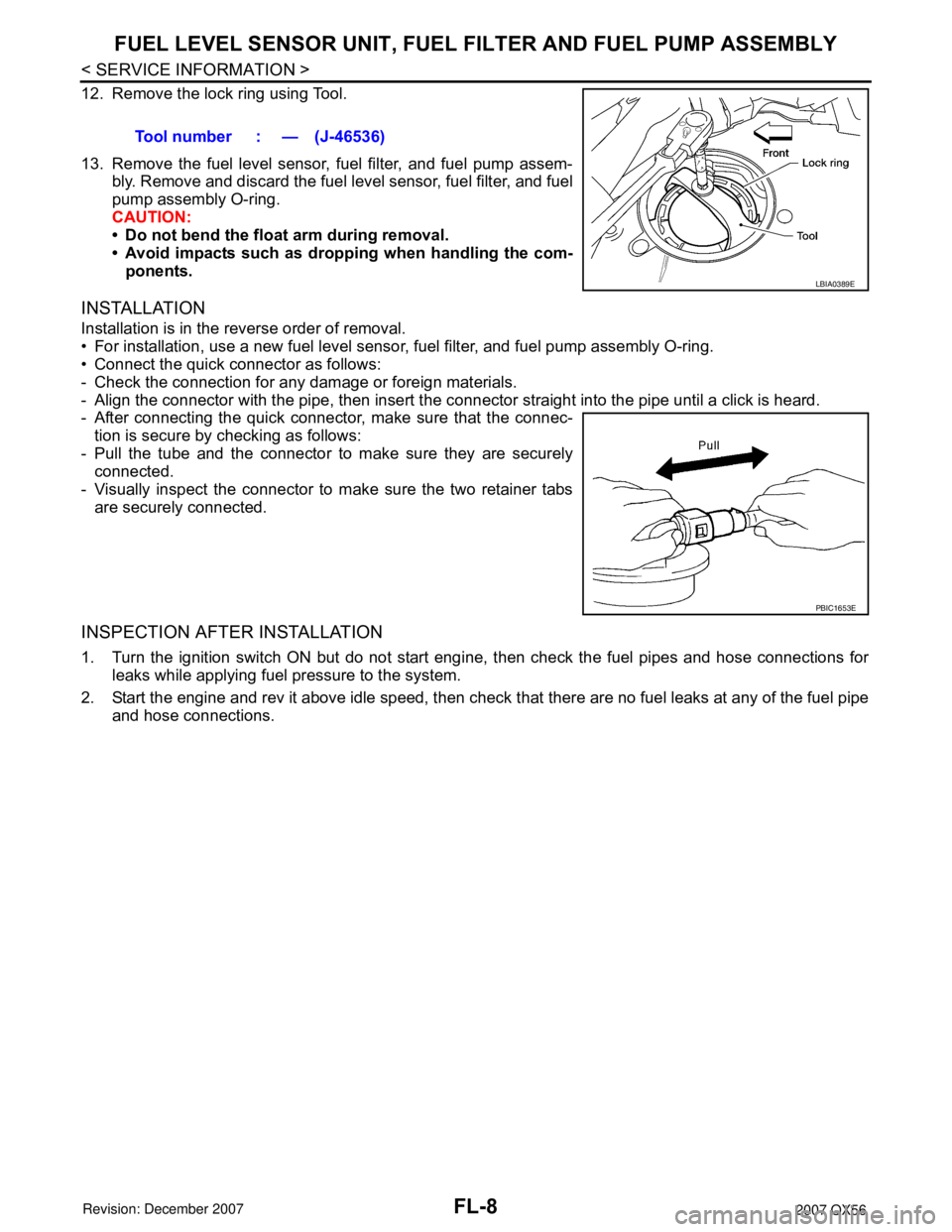
12. Remove the lock ring using Tool.
13. Remove the fuel level sensor, fuel filter, and fuel pump assem-
bly. Remove and discard the fuel level sensor, fuel filter, and fuel
pump assembly O-ring.
CAUTION:
• Do not bend the float arm during removal.
• Avoid impacts such as dropping when handling the com-
ponents.
INSTALLATION
Installation is in the reverse order of removal.
• For installation, use a new fuel level sensor, fuel filter, and fuel pump assembly O-ring.
• Connect the quick connector as follows:
- Check the connection for any damage or foreign materials.
- Align the connector with the pipe, then insert the connector straight into the pipe until a click is heard.
- After connecting the quick connector, make sure that the connec-
tion is secure by checking as follows:
- Pull the tube and the connector to make sure they are securely
connected.
- Visually inspect the connector to make sure the two retainer tabs
are securely connected.
INSPECTION AFTER INSTALLATION
1. Turn the ignition switch ON but do not start engine, then check the fuel pipes and hose connections for
leaks while applying fuel pressure to the system.
2. Start the engine and rev it above idle speed, then check that there are no fuel leaks at any of the fuel pipe
and hose connections.Tool number : — (J-46536)
LBIA0389E
PBIC1653E
Page 1945 of 3061

FL-14
< SERVICE INFORMATION >
FUEL TANK
INSPECTION AFTER INSTALLATION
1. Turn the ignition switch ON but do not start engine, then check the fuel pipe and hose connections for
leaks while applying fuel pressure.
2. Start the engine and rev it above idle, then check that there are no fuel leaks at any of the fuel pipe and
hose connections.
Page 1948 of 3061
FSU-2
< SERVICE INFORMATION >
PRECAUTIONS
SERVICE INFORMATION
PRECAUTIONS
PrecautionINFOID:0000000003532631
• When installing the rubber bushings, the final tightening must be done under unladen condition and with the
tires on level ground. Oil will shorten the life of the rubber bushings, so wipe off any spilled oil immediately.
• Unladen condition means the fuel tank, engine coolant and lubricants are at the full specification. The spare
tire, jack, hand tools, and mats are in their designated positions.
• After installing suspension components, check the wheel alignment.
• Lock nuts are not reusable. Always use new lock nuts for installation. New lock nuts are pre-oiled, do not
apply any additional lubrication.
Page 1954 of 3061
FSU-8
< SERVICE INFORMATION >
ON-VEHICLE SERVICE
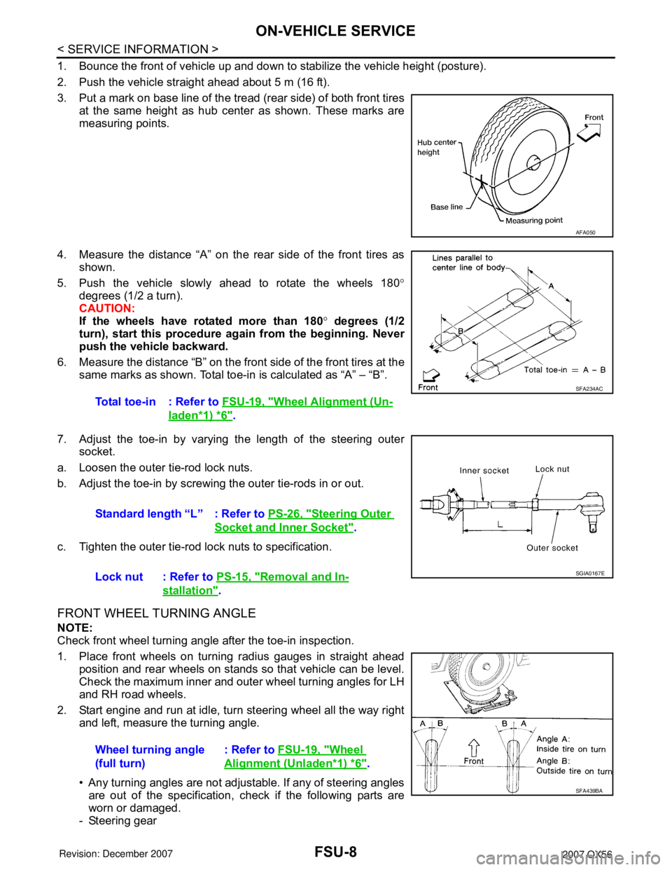
1. Bounce the front of vehicle up and down to stabilize the vehicle height (posture).
2. Push the vehicle straight ahead about 5 m (16 ft).
3. Put a mark on base line of the tread (rear side) of both front tires
at the same height as hub center as shown. These marks are
measuring points.
4. Measure the distance “A” on the rear side of the front tires as
shown.
5. Push the vehicle slowly ahead to rotate the wheels 180°
degrees (1/2 a turn).
CAUTION:
If the wheels have rotated more than 180° degrees (1/2
turn), start this procedure again from the beginning. Never
push the vehicle backward.
6. Measure the distance “B” on the front side of the front tires at the
same marks as shown. Total toe-in is calculated as “A” – “B”.
7. Adjust the toe-in by varying the length of the steering outer
socket.
a. Loosen the outer tie-rod lock nuts.
b. Adjust the toe-in by screwing the outer tie-rods in or out.
c. Tighten the outer tie-rod lock nuts to specification.
FRONT WHEEL TURNING ANGLE
NOTE:
Check front wheel turning angle after the toe-in inspection.
1. Place front wheels on turning radius gauges in straight ahead
position and rear wheels on stands so that vehicle can be level.
Check the maximum inner and outer wheel turning angles for LH
and RH road wheels.
2. Start engine and run at idle, turn steering wheel all the way right
and left, measure the turning angle.
• Any turning angles are not adjustable. If any of steering angles
are out of the specification, check if the following parts are
worn or damaged.
- Steering gear
AFA050
Total toe-in : Refer to FSU-19, "Wheel Alignment (Un-
laden*1) *6".
SFA234AC
Standard length “L” : Refer to PS-26, "Steering Outer
Socket and Inner Socket".
Lock nut : Refer to PS-15, "
Removal and In-
stallation".
SGIA0167E
Wheel turning angle
(full turn): Refer to FSU-19, "Wheel
Alignment (Unladen*1) *6".
SFA439BA
Page 1958 of 3061

FSU-12
< SERVICE INFORMATION >
STABILIZER BAR
STABILIZER BAR
Removal and InstallationINFOID:0000000003532640
REMOVAL
1. Remove engine under cover using power tool.
2. Remove stabilizer bar mounting bracket bolts and connecting
rod nuts using power tool, as shown.
3. Remove bushings from stabilizer bar.
INSPECTION AFTER REMOVAL
• Check stabilizer bar for twist and deformation. Replace if necessary.
• Check rubber bushing for cracks, wear and deterioration. Replace if necessary.
INSTALLATION
Installation is in the reverse order of removal.
• Tighten all nuts and bolts to specification. Refer to FSU-5, "
Component" .
LEIA0094E
Page 1967 of 3061

GI-1
GENERAL INFORMATION
C
D
E
F
G
H
I
J
K
L
MB
GI
SECTION GI
N
O
P
CONTENTS
GENERAL INFORMATION
SERVICE INFORMATION ............................2
PRECAUTIONS ...................................................2
Description ................................................................2
Precaution for Supplemental Restraint System
(SRS) "AIR BAG" and "SEAT BELT PRE-TEN-
SIONER" ...................................................................
2
Precaution for NVIS/IVIS (NISSAN/INFINITI VE-
HICLE IMMOBILIZER SYSTEM - NATS) (If
Equipped) ..................................................................
2
General Precaution ...................................................3
Precaution for Three Way Catalyst ...........................4
Precaution for Fuel (Unleaded Premium Gasoline
Required) ..................................................................
4
Precaution for Multiport Fuel Injection System or
Engine Control System .............................................
5
Precaution for Hoses .................................................5
Precaution for Engine Oils ........................................6
Precaution for Air Conditioning .................................6
HOW TO USE THIS MANUAL ............................7
Description ................................................................7
Terms ........................................................................7
Units ..........................................................................7
Relation between Illustrations and Descriptions .......7
Contents ....................................................................8
Component ................................................................8
How to Follow Trouble Diagnosis ..............................9
How to Read Wiring Diagram ..................................13
Abbreviations ..........................................................20
SERVICE INFORMATION FOR ELECTRICAL
INCIDENT ...........................................................
22
How to Check Terminal ...........................................22
How to Perform Efficient Diagnosis for an Electri-
cal Incident ..............................................................
25
Control Units and Electrical Parts ............................32
CONSULT-II CHECKING SYSTEM ..................35
Description ...............................................................35
Function and System Application ............................35
Nickel Metal Hydride Battery Replacement .............36
Checking Equipment ...............................................36
CONSULT-II Start Procedure ..................................36
CONSULT-II Data Link Connector (DLC) Circuit .....38
LIFTING POINT .................................................40
Pantograph Jack ......................................................40
Garage Jack and Safety Stand ................................40
2-Pole Lift ................................................................40
TOW TRUCK TOWING .....................................42
Tow Truck Towing ...................................................42
Vehicle Recovery (Freeing a stuck vehicle) ............43
TIGHTENING TORQUE OF STANDARD
BOLTS ...............................................................
44
Tightening Torque Table .........................................44
RECOMMENDED CHEMICAL PRODUCTS
AND SEALANTS ...............................................
45
Recommended Chemical Product and Sealant .......45
IDENTIFICATION INFORMATION ....................46
Model Variation ........................................................46
Identification Number ...............................................47
Dimensions ..............................................................48
Wheels & Tires ........................................................48
TERMINOLOGY ................................................50
SAE J1930 Terminology List ...................................50
Page 1970 of 3061
GI-4
< SERVICE INFORMATION >
PRECAUTIONS
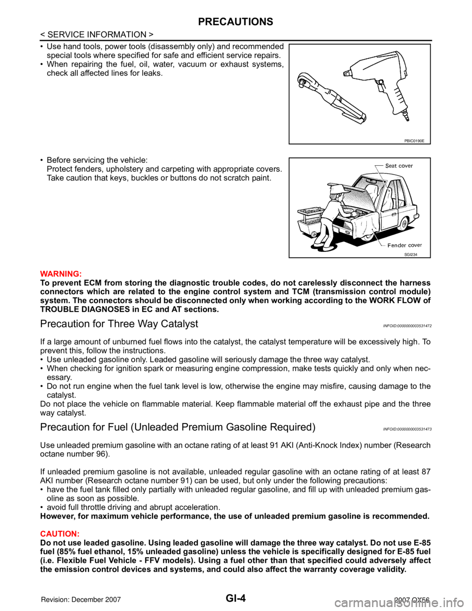
• Use hand tools, power tools (disassembly only) and recommended
special tools where specified for safe and efficient service repairs.
• When repairing the fuel, oil, water, vacuum or exhaust systems,
check all affected lines for leaks.
• Before servicing the vehicle:
Protect fenders, upholstery and carpeting with appropriate covers.
Take caution that keys, buckles or buttons do not scratch paint.
WARNING:
To prevent ECM from storing the diagnostic trouble codes, do not carelessly disconnect the harness
connectors which are related to the engine control system and TCM (transmission control module)
system. The connectors should be disconnected only when working according to the WORK FLOW of
TROUBLE DIAGNOSES in EC and AT sections.
Precaution for Three Way CatalystINFOID:0000000003531472
If a large amount of unburned fuel flows into the catalyst, the catalyst temperature will be excessively high. To
prevent this, follow the instructions.
• Use unleaded gasoline only. Leaded gasoline will seriously damage the three way catalyst.
• When checking for ignition spark or measuring engine compression, make tests quickly and only when nec-
essary.
• Do not run engine when the fuel tank level is low, otherwise the engine may misfire, causing damage to the
catalyst.
Do not place the vehicle on flammable material. Keep flammable material off the exhaust pipe and the three
way catalyst.
Precaution for Fuel (Unleaded Premium Gasoline Required)INFOID:0000000003531473
Use unleaded premium gasoline with an octane rating of at least 91 AKI (Anti-Knock Index) number (Research
octane number 96).
If unleaded premium gasoline is not available, unleaded regular gasoline with an octane rating of at least 87
AKI number (Research octane number 91) can be used, but only under the following precautions:
• have the fuel tank filled only partially with unleaded regular gasoline, and fill up with unleaded premium gas-
oline as soon as possible.
• avoid full throttle driving and abrupt acceleration.
However, for maximum vehicle performance, the use of unleaded premium gasoline is recommended.
CAUTION:
Do not use leaded gasoline. Using leaded gasoline will damage the three way catalyst. Do not use E-85
fuel (85% fuel ethanol, 15% unleaded gasoline) unless the vehicle is specifically designed for E-85 fuel
(i.e. Flexible Fuel Vehicle - FFV models). Using a fuel other than that specified could adversely affect
the emission control devices and systems, and could also affect the warranty coverage validity.
PBIC0190E
SGI234
Page 1991 of 3061
SERVICE INFORMATION FOR ELECTRICAL INCIDENT
GI-25
< SERVICE INFORMATION >
C
D
E
F
G
H
I
J
K
L
MB
GI
N
O
P
How to Perform Efficient Diagnosis for an Electrical IncidentINFOID:0000000003531488
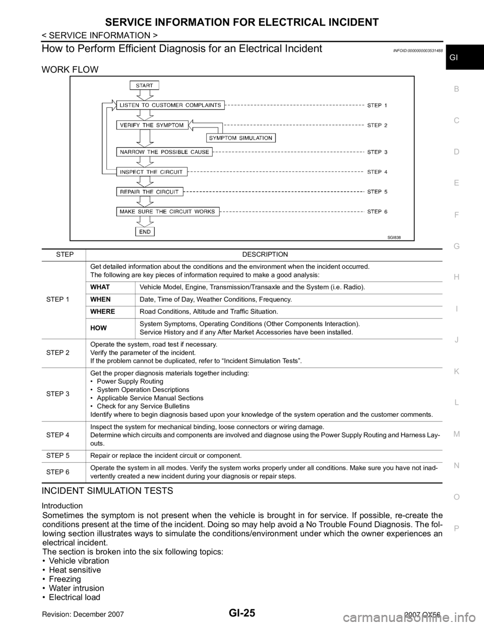
WORK FLOW
INCIDENT SIMULATION TESTS
Introduction
Sometimes the symptom is not present when the vehicle is brought in for service. If possible, re-create the
conditions present at the time of the incident. Doing so may help avoid a No Trouble Found Diagnosis. The fol-
lowing section illustrates ways to simulate the conditions/environment under which the owner experiences an
electrical incident.
The section is broken into the six following topics:
• Vehicle vibration
• Heat sensitive
• Freezing
• Water intrusion
• Electrical load
SGI838
STEP DESCRIPTION
STEP 1Get detailed information about the conditions and the environment when the incident occurred.
The following are key pieces of information required to make a good analysis:
WHATVehicle Model, Engine, Transmission/Transaxle and the System (i.e. Radio).
WHENDate, Time of Day, Weather Conditions, Frequency.
WHERERoad Conditions, Altitude and Traffic Situation.
HOWSystem Symptoms, Operating Conditions (Other Components Interaction).
Service History and if any After Market Accessories have been installed.
STEP 2Operate the system, road test if necessary.
Verify the parameter of the incident.
If the problem cannot be duplicated, refer to “Incident Simulation Tests”.
STEP 3Get the proper diagnosis materials together including:
• Power Supply Routing
• System Operation Descriptions
• Applicable Service Manual Sections
• Check for any Service Bulletins
Identify where to begin diagnosis based upon your knowledge of the system operation and the customer comments.
STEP 4Inspect the system for mechanical binding, loose connectors or wiring damage.
Determine which circuits and components are involved and diagnose using the Power Supply Routing and Harness Lay-
outs.
STEP 5 Repair or replace the incident circuit or component.
STEP 6Operate the system in all modes. Verify the system works properly under all conditions. Make sure you have not inad-
vertently created a new incident during your diagnosis or repair steps.