Page 2153 of 3061
LAN-22
< SERVICE INFORMATION >[CAN FUNDAMENTAL]
TROUBLE DIAGNOSES WORK FLOW
• For a description of Diag on CAN, refer to LAN-5, "Diag on CAN".
2. CAN DIAG SUPPORT MNTR: Check each item on “CAN DIAG SUPPORT MNTR”. Draw a line on the
diagnosis sheet to indicate the error circuit.
a. Reception item of “ENGINE”: On “TCM”, “UNKWN” is indicated. This means ECM cannot receive the sig-
nal from TCM. Draw a line to indicate an error between ECM and TCM (line 2-a in the figure).
NOTE:
If “UNKWN” is indicated on “TRANSMIT DIAG”, then the control unit cannot transmit CAN communication
signal to each unit. Draw a line between the control unit and the splice.
b. Reception item of “ADAPTIVE LIGHT”: On “TCM”, “UNKWN” is indicated. This means AFS cannot
receive the signal from TCM. Draw a line to indicate an error between AFS and TCM (line 2-b in the fig-
ure).
SKIB8892E
Page 2160 of 3061
TROUBLE DIAGNOSES WORK FLOW
LAN-29
< SERVICE INFORMATION >[CAN FUNDAMENTAL]
C
D
E
F
G
H
I
J
L
MA
B
LAN
N
O
P
1. SELF-DIAG RESULTS: Inspect the control units indicating “U1000” or “U1001” on SELF-DIAG RESULTS.
2. CAN DIAG SUPPORT MNTR (with PAST): Check the CAN DIAG SUPPORT MNTR (with PAST) of units
indicating “U1000” or “U1001” on SELF-DIAG RESULTS. Draw a line on the diagnosis sheet to indicate
the possible error circuit.
NOTE:
For the details of each indication on CAN DIAG SUPPORT MNTR, refer to LAN-40, "
CAN Diagnostic Sup-
port Monitor".
a. Reception item of “ENGINE”: “VDC/TCS/ABS”, “3” is indicated in the “PAST”. This means ECM could not
receive the signal from ABS in the past. Draw a line between ECM and ABS (line 2-a in the figure).
SKIB8731E
Page 2175 of 3061
![INFINITI QX56 2007 Factory Service Manual LAN-44
< SERVICE INFORMATION >[CAN]
TROUBLE DIAGNOSIS
CAN System Specification Chart
INFOID:0000000003533627
Determine CAN system type from the following specification chart. Then choose the correct d INFINITI QX56 2007 Factory Service Manual LAN-44
< SERVICE INFORMATION >[CAN]
TROUBLE DIAGNOSIS
CAN System Specification Chart
INFOID:0000000003533627
Determine CAN system type from the following specification chart. Then choose the correct d](/manual-img/42/57029/w960_57029-2174.png)
LAN-44
< SERVICE INFORMATION >[CAN]
TROUBLE DIAGNOSIS
CAN System Specification Chart
INFOID:0000000003533627
Determine CAN system type from the following specification chart. Then choose the correct diagnosis sheet.
NOTE:
Refer to LAN-14, "
Trouble Diagnosis Procedure" for how to use CAN system specification chart.
X: Applicable
VEHICLE EQUIPMENT IDENTIFICATION INFORMATION
NOTE:
Check CAN system type from the vehicle shape and equipment.
CAN Communication Signal ChartINFOID:0000000003533628
Refer to LAN-13, "How to Use CAN Communication Signal Chart" for how to use CAN communication signal
chart.
TYPE 1/TYPE 2
NOTE:
Refer to LAN-37, "
Abbreviation List" for the abbreviations of the connecting units.
T: Transmit R: Receive
Body typeWagon
Axle 2WD AWD
EngineVK56DE
Transmission A/T
Brake controlVDC
ICC system X X
CAN system type 1234
Diagnosis sheetLAN-57
LAN-58LAN-59LAN-60
CAN communication signal chartLAN-44, "CAN Communication Sig-
nal Chart"
LAN-44, "CAN Communication Sig-
nal Chart"
BKIA0219E
Signal name/Connecting unitECM
TCM
LASER
ICC
ADP
BCM
DISP
HVAC
M&A
STRG
ABS
IPDM-E
A/C compressor request signal TR
Accelerator pedal position signal T R R R
ASCD CRUISE lamp signal T R
ASCD OD cancel request signal T R
ASCD operation signal T R
ASCD SET lamp signal T R
Battery voltage signal T R
Closed throttle position signal T R R
Cooling fan speed request signal TR
Engine coolant temperature signal T R R
Page 2176 of 3061
![INFINITI QX56 2007 Factory Service Manual TROUBLE DIAGNOSIS
LAN-45
< SERVICE INFORMATION >[CAN]
C
D
E
F
G
H
I
J
L
MA
B
LAN
N
O
P
Engine speed signal T R R R R R R
Engine status signal T R
Fuel consumption monitor signalTR
RT
ICC steering swit INFINITI QX56 2007 Factory Service Manual TROUBLE DIAGNOSIS
LAN-45
< SERVICE INFORMATION >[CAN]
C
D
E
F
G
H
I
J
L
MA
B
LAN
N
O
P
Engine speed signal T R R R R R R
Engine status signal T R
Fuel consumption monitor signalTR
RT
ICC steering swit](/manual-img/42/57029/w960_57029-2175.png)
TROUBLE DIAGNOSIS
LAN-45
< SERVICE INFORMATION >[CAN]
C
D
E
F
G
H
I
J
L
MA
B
LAN
N
O
P
Engine speed signal T R R R R R R
Engine status signal T R
Fuel consumption monitor signalTR
RT
ICC steering switch signal T R
Malfunction indicator lamp signal T R
Wide open throttle position signal T R
A/T CHECK indicator lamp signal T R
A/T fluid temperature sensor signal T R
A/T position indicator lamp signal T R R
A/T self-diagnosis signal R T
Current gear position signal T R R
Output shaft revolution signal R T R
P range signal T R R R R
Turbine revolution signal R T R
ICC sensor signal T R
Buzzer output signalTR
TR
ICC OD cancel request signal R R T
ICC operation signal R R T
ICC system display signal T R
System setting signalTR
RT
A/C switch signal R T R
Blower fan motor switch signal R T
Day time running light request signal T R R
Door switch signal R T R R R
Front fog light request signal T R
Front wiper request signal R T R
High beam request signal T R R
Horn chirp signal T R
Ignition switch signal R T R
Key fob door unlock signal R T
Key fob ID signal R T
Key switch signal R T
Low beam request signal T R
Position light request signal T R R
Rear window defogger switch signal T R R
Sleep wake up signal R T R R
Theft warning horn request signal T R
Tire pressure data signal T R
Tire pressure signal T R R
Turn indicator signal T RSignal name/Connecting unit
ECM
TCM
LASER
ICC
ADP
BCM
DISP
HVAC
M&A
STRG
ABS
IPDM-E
Page 2178 of 3061
![INFINITI QX56 2007 Factory Service Manual TROUBLE DIAGNOSIS
LAN-47
< SERVICE INFORMATION >[CAN]
C
D
E
F
G
H
I
J
L
MA
B
LAN
N
O
P
Cooling fan speed request signal TR
Engine coolant temperature signal T R R
Engine speed signal T R R R R R R R
E INFINITI QX56 2007 Factory Service Manual TROUBLE DIAGNOSIS
LAN-47
< SERVICE INFORMATION >[CAN]
C
D
E
F
G
H
I
J
L
MA
B
LAN
N
O
P
Cooling fan speed request signal TR
Engine coolant temperature signal T R R
Engine speed signal T R R R R R R R
E](/manual-img/42/57029/w960_57029-2177.png)
TROUBLE DIAGNOSIS
LAN-47
< SERVICE INFORMATION >[CAN]
C
D
E
F
G
H
I
J
L
MA
B
LAN
N
O
P
Cooling fan speed request signal TR
Engine coolant temperature signal T R R
Engine speed signal T R R R R R R R
Engine status signal T R
Fuel consumption monitor signalTR
RT
ICC steering switch signal T R
Malfunction indicator lamp signal T R
Wide open throttle position signal T R
A/T CHECK indicator lamp signal T R
A/T fluid temperature sensor signal T R
A/T position indicator lamp signal T R R R
A/T self-diagnosis signal R T
Current gear position signal T R R
Output shaft revolution signal R T R R
P range signal T R R R R
Turbine revolution signal R T R
ICC sensor signal T R
Buzzer output signalTR
TR
ICC OD cancel request signal R R T
ICC operation signal R R T
ICC system display signal T R
System setting signalTR
RT
A/C switch signal R T R
Blower fan motor switch signal R T
Day time running light request signal T R R
Door switch signal R T R R R
Front fog light request signal T R
Front wiper request signal R T R
High beam request signal T R R
Horn chirp signal T R
Ignition switch signal R T R
Key fob door unlock signal R T
Key fob ID signal R T
Key switch signal R T
Low beam request signal T R
Position light request signal T R R
Rear window defogger switch signal T R R
Sleep wake up signal R T R R
Theft warning horn request signal T R
Tire pressure data signal T RSignal name/Connecting unit
ECM
TCM
LASER
ICC
ADP
BCM
DISP
HVAC
M&A
STRG
4WD
ABS
IPDM-E
Page 2240 of 3061

HEADLAMP (FOR CANADA) - DAYTIME LIGHT SYSTEM -
LT-33
< SERVICE INFORMATION >
C
D
E
F
G
H
I
J
L
MA
B
LT
N
O
P
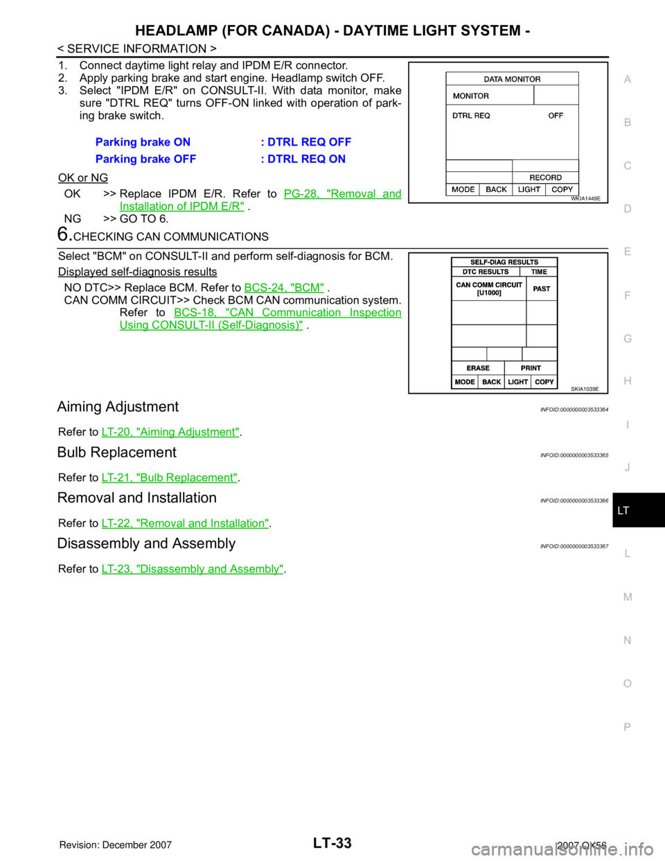
1. Connect daytime light relay and IPDM E/R connector.
2. Apply parking brake and start engine. Headlamp switch OFF.
3. Select "IPDM E/R" on CONSULT-II. With data monitor, make
sure "DTRL REQ" turns OFF-ON linked with operation of park-
ing brake switch.
OK or NG
OK >> Replace IPDM E/R. Refer to PG-28, "Removal and
Installation of IPDM E/R" .
NG >> GO TO 6.
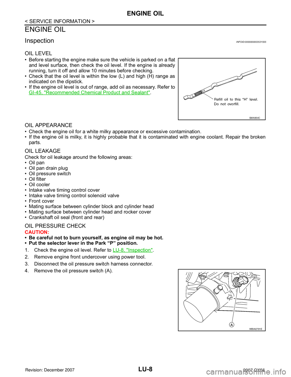
6.CHECKING CAN COMMUNICATIONS
Select "BCM" on CONSULT-II and perform self-diagnosis for BCM.
Displayed self-diagnosis results
NO DTC>> Replace BCM. Refer to BCS-24, "BCM" .
CAN COMM CIRCUIT>> Check BCM CAN communication system.
Refer to BCS-18, "
CAN Communication Inspection
Using CONSULT-II (Self-Diagnosis)" .
Aiming AdjustmentINFOID:0000000003533364
Refer to LT-20, "Aiming Adjustment".
Bulb ReplacementINFOID:0000000003533365
Refer to LT-21, "Bulb Replacement".
Removal and InstallationINFOID:0000000003533366
Refer to LT-22, "Removal and Installation".
Disassembly and AssemblyINFOID:0000000003533367
Refer to LT-23, "Disassembly and Assembly". Parking brake ON : DTRL REQ OFF
Parking brake OFF : DTRL REQ ON
WKIA1449E
SKIA1039E
Page 2353 of 3061

LU-8
< SERVICE INFORMATION >
ENGINE OIL
ENGINE OIL
InspectionINFOID:0000000003531555
OIL LEVEL
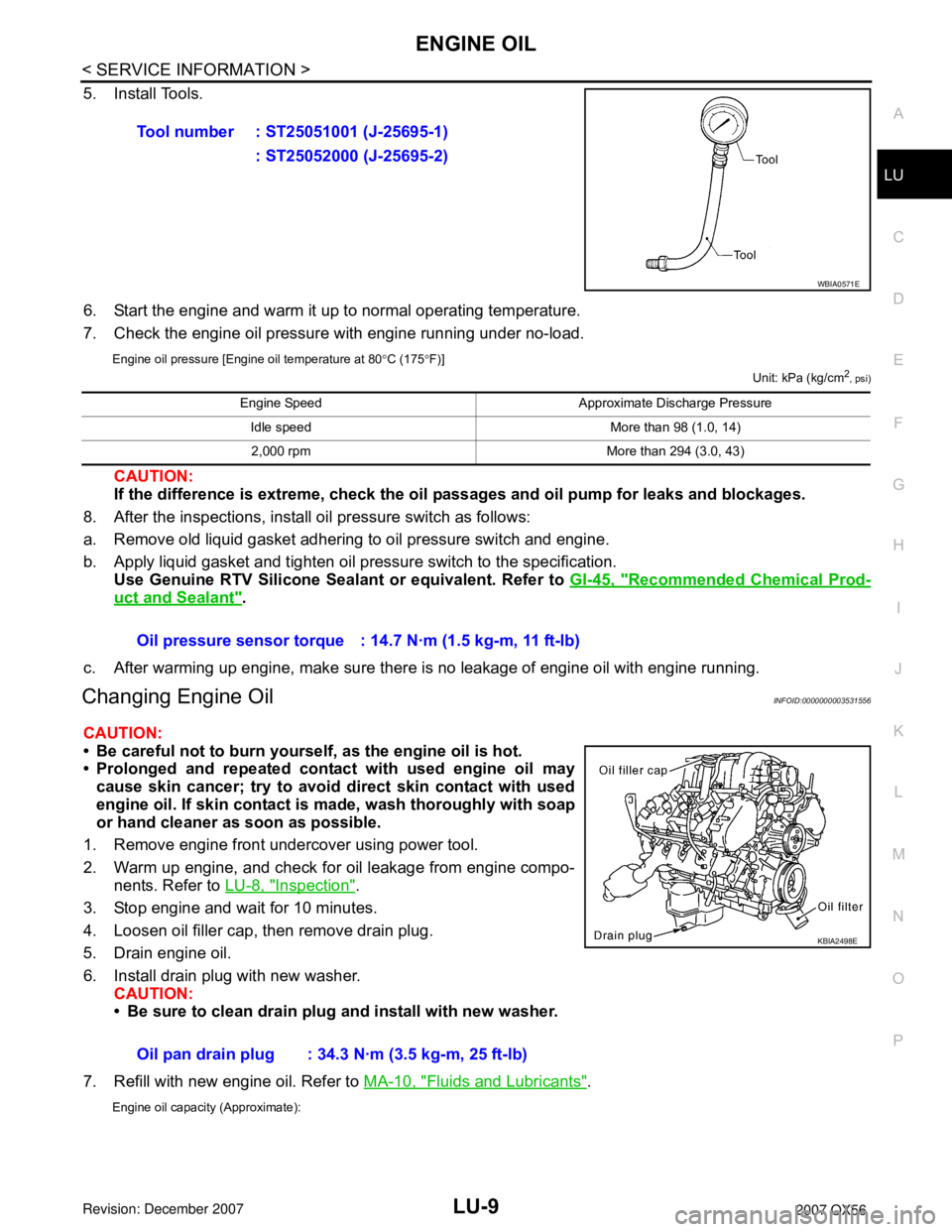
• Before starting the engine make sure the vehicle is parked on a flat
and level surface, then check the oil level. If the engine is already
running, turn it off and allow 10 minutes before checking.
• Check that the oil level is within the low (L) and high (H) range as
indicated on the dipstick.
• If the engine oil level is out of range, add oil as necessary. Refer to
GI-45, "
Recommended Chemical Product and Sealant".
OIL APPEARANCE
• Check the engine oil for a white milky appearance or excessive contamination.
• If the engine oil is milky, it is highly probable that it is contaminated with engine coolant. Repair the broken
parts.
OIL LEAKAGE
Check for oil leakage around the following areas:
•Oil pan
• Oil pan drain plug
• Oil pressure switch
• Oil filter
• Oil cooler
• Intake valve timing control cover
• Intake valve timing control solenoid valve
• Front cover
• Mating surface between cylinder block and cylinder head
• Mating surface between cylinder head and rocker cover
• Crankshaft oil seal (front and rear)
OIL PRESSURE CHECK
CAUTION:
• Be careful not to burn yourself, as engine oil may be hot.
• Put the selector lever in the Park “P” position.
1. Check the engine oil level. Refer to LU-8, "
Inspection".
2. Remove engine front undercover using power tool.
3. Disconnect the oil pressure switch harness connector.
4. Remove the oil pressure switch (A).
SMA954C
WBIA0791E
Page 2354 of 3061

ENGINE OIL
LU-9
< SERVICE INFORMATION >
C
D
E
F
G
H
I
J
K
L
MA
LU
N
P O
5. Install Tools.
6. Start the engine and warm it up to normal operating temperature.
7. Check the engine oil pressure with engine running under no-load.
Engine oil pressure [Engine oil temperature at 80°C (175°F)]
Unit: kPa (kg/cm2
, psi)
CAUTION:
If the difference is extreme, check the oil passages and oil pump for leaks and blockages.
8. After the inspections, install oil pressure switch as follows:
a. Remove old liquid gasket adhering to oil pressure switch and engine.
b. Apply liquid gasket and tighten oil pressure switch to the specification.
Use Genuine RTV Silicone Sealant or equivalent. Refer to GI-45, "
Recommended Chemical Prod-
uct and Sealant".
c. After warming up engine, make sure there is no leakage of engine oil with engine running.
Changing Engine OilINFOID:0000000003531556
CAUTION:
• Be careful not to burn yourself, as the engine oil is hot.
• Prolonged and repeated contact with used engine oil may
cause skin cancer; try to avoid direct skin contact with used
engine oil. If skin contact is made, wash thoroughly with soap
or hand cleaner as soon as possible.
1. Remove engine front undercover using power tool.
2. Warm up engine, and check for oil leakage from engine compo-
nents. Refer to LU-8, "
Inspection".
3. Stop engine and wait for 10 minutes.
4. Loosen oil filler cap, then remove drain plug.
5. Drain engine oil.
6. Install drain plug with new washer.
CAUTION:
• Be sure to clean drain plug and install with new washer.
7. Refill with new engine oil. Refer to MA-10, "
Fluids and Lubricants".
Engine oil capacity (Approximate):
Tool number : ST25051001 (J-25695-1)
: ST25052000 (J-25695-2)
WBIA0571E
Engine Speed Approximate Discharge Pressure
Idle speed More than 98 (1.0, 14)
2,000 rpm More than 294 (3.0, 43)
Oil pressure sensor torque : 14.7 N·m (1.5 kg-m, 11 ft-lb)
Oil pan drain plug : 34.3 N·m (3.5 kg-m, 25 ft-lb)
KBIA2498E