2007 INFINITI QX56 air condition
[x] Cancel search: air conditionPage 1952 of 3061
FSU-6
< SERVICE INFORMATION >
ON-VEHICLE SERVICE
ON-VEHICLE SERVICE
Front Suspension PartsINFOID:0000000003532636
Check front suspension parts for excessive play, cracks, wear and
other damage.
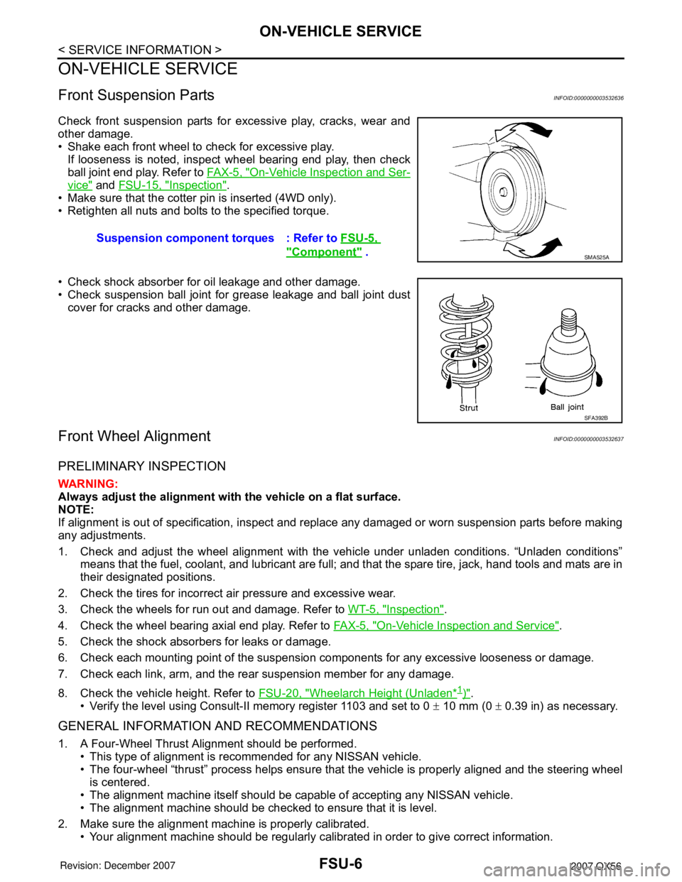
• Shake each front wheel to check for excessive play.
If looseness is noted, inspect wheel bearing end play, then check
ball joint end play. Refer to FA X - 5 , "
On-Vehicle Inspection and Ser-
vice" and FSU-15, "Inspection".
• Make sure that the cotter pin is inserted (4WD only).
• Retighten all nuts and bolts to the specified torque.
• Check shock absorber for oil leakage and other damage.
• Check suspension ball joint for grease leakage and ball joint dust
cover for cracks and other damage.
Front Wheel AlignmentINFOID:0000000003532637
PRELIMINARY INSPECTION
WARNING:
Always adjust the alignment with the vehicle on a flat surface.
NOTE:
If alignment is out of specification, inspect and replace any damaged or worn suspension parts before making
any adjustments.
1. Check and adjust the wheel alignment with the vehicle under unladen conditions. “Unladen conditions”
means that the fuel, coolant, and lubricant are full; and that the spare tire, jack, hand tools and mats are in
their designated positions.
2. Check the tires for incorrect air pressure and excessive wear.
3. Check the wheels for run out and damage. Refer to WT-5, "
Inspection".
4. Check the wheel bearing axial end play. Refer to FA X - 5 , "
On-Vehicle Inspection and Service".
5. Check the shock absorbers for leaks or damage.
6. Check each mounting point of the suspension components for any excessive looseness or damage.
7. Check each link, arm, and the rear suspension member for any damage.
8. Check the vehicle height. Refer to FSU-20, "
Wheelarch Height (Unladen*1)".
• Verify the level using Consult-II memory register 1103 and set to 0 ± 10 mm (0 ± 0.39 in) as necessary.
GENERAL INFORMATION AND RECOMMENDATIONS
1. A Four-Wheel Thrust Alignment should be performed.
• This type of alignment is recommended for any NISSAN vehicle.
• The four-wheel “thrust” process helps ensure that the vehicle is properly aligned and the steering wheel
is centered.
• The alignment machine itself should be capable of accepting any NISSAN vehicle.
• The alignment machine should be checked to ensure that it is level.
2. Make sure the alignment machine is properly calibrated.
• Your alignment machine should be regularly calibrated in order to give correct information.Suspension component torques : Refer to FSU-5,
"Component" . SMA525A
SFA392B
Page 1967 of 3061

GI-1
GENERAL INFORMATION
C
D
E
F
G
H
I
J
K
L
MB
GI
SECTION GI
N
O
P
CONTENTS
GENERAL INFORMATION
SERVICE INFORMATION ............................2
PRECAUTIONS ...................................................2
Description ................................................................2
Precaution for Supplemental Restraint System
(SRS) "AIR BAG" and "SEAT BELT PRE-TEN-
SIONER" ...................................................................
2
Precaution for NVIS/IVIS (NISSAN/INFINITI VE-
HICLE IMMOBILIZER SYSTEM - NATS) (If
Equipped) ..................................................................
2
General Precaution ...................................................3
Precaution for Three Way Catalyst ...........................4
Precaution for Fuel (Unleaded Premium Gasoline
Required) ..................................................................
4
Precaution for Multiport Fuel Injection System or
Engine Control System .............................................
5
Precaution for Hoses .................................................5
Precaution for Engine Oils ........................................6
Precaution for Air Conditioning .................................6
HOW TO USE THIS MANUAL ............................7
Description ................................................................7
Terms ........................................................................7
Units ..........................................................................7
Relation between Illustrations and Descriptions .......7
Contents ....................................................................8
Component ................................................................8
How to Follow Trouble Diagnosis ..............................9
How to Read Wiring Diagram ..................................13
Abbreviations ..........................................................20
SERVICE INFORMATION FOR ELECTRICAL
INCIDENT ...........................................................
22
How to Check Terminal ...........................................22
How to Perform Efficient Diagnosis for an Electri-
cal Incident ..............................................................
25
Control Units and Electrical Parts ............................32
CONSULT-II CHECKING SYSTEM ..................35
Description ...............................................................35
Function and System Application ............................35
Nickel Metal Hydride Battery Replacement .............36
Checking Equipment ...............................................36
CONSULT-II Start Procedure ..................................36
CONSULT-II Data Link Connector (DLC) Circuit .....38
LIFTING POINT .................................................40
Pantograph Jack ......................................................40
Garage Jack and Safety Stand ................................40
2-Pole Lift ................................................................40
TOW TRUCK TOWING .....................................42
Tow Truck Towing ...................................................42
Vehicle Recovery (Freeing a stuck vehicle) ............43
TIGHTENING TORQUE OF STANDARD
BOLTS ...............................................................
44
Tightening Torque Table .........................................44
RECOMMENDED CHEMICAL PRODUCTS
AND SEALANTS ...............................................
45
Recommended Chemical Product and Sealant .......45
IDENTIFICATION INFORMATION ....................46
Model Variation ........................................................46
Identification Number ...............................................47
Dimensions ..............................................................48
Wheels & Tires ........................................................48
TERMINOLOGY ................................................50
SAE J1930 Terminology List ...................................50
Page 1972 of 3061
GI-6
< SERVICE INFORMATION >
PRECAUTIONS
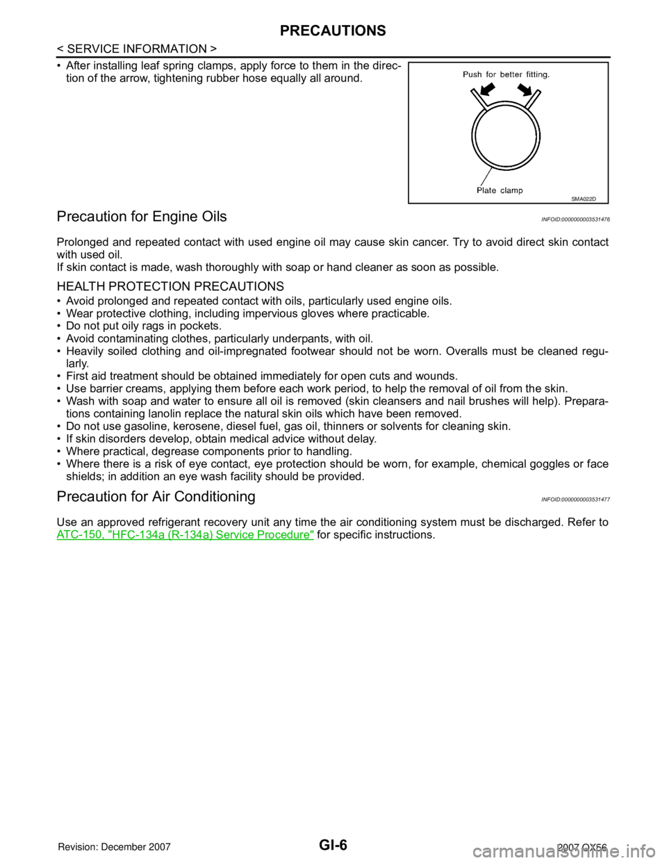
• After installing leaf spring clamps, apply force to them in the direc-
tion of the arrow, tightening rubber hose equally all around.
Precaution for Engine OilsINFOID:0000000003531476
Prolonged and repeated contact with used engine oil may cause skin cancer. Try to avoid direct skin contact
with used oil.
If skin contact is made, wash thoroughly with soap or hand cleaner as soon as possible.
HEALTH PROTECTION PRECAUTIONS
• Avoid prolonged and repeated contact with oils, particularly used engine oils.
• Wear protective clothing, including impervious gloves where practicable.
• Do not put oily rags in pockets.
• Avoid contaminating clothes, particularly underpants, with oil.
• Heavily soiled clothing and oil-impregnated footwear should not be worn. Overalls must be cleaned regu-
larly.
• First aid treatment should be obtained immediately for open cuts and wounds.
• Use barrier creams, applying them before each work period, to help the removal of oil from the skin.
• Wash with soap and water to ensure all oil is removed (skin cleansers and nail brushes will help). Prepara-
tions containing lanolin replace the natural skin oils which have been removed.
• Do not use gasoline, kerosene, diesel fuel, gas oil, thinners or solvents for cleaning skin.
• If skin disorders develop, obtain medical advice without delay.
• Where practical, degrease components prior to handling.
• Where there is a risk of eye contact, eye protection should be worn, for example, chemical goggles or face
shields; in addition an eye wash facility should be provided.
Precaution for Air ConditioningINFOID:0000000003531477
Use an approved refrigerant recovery unit any time the air conditioning system must be discharged. Refer to
ATC-150, "
HFC-134a (R-134a) Service Procedure" for specific instructions.
SMA022D
Page 1986 of 3061
GI-20
< SERVICE INFORMATION >
HOW TO USE THIS MANUAL
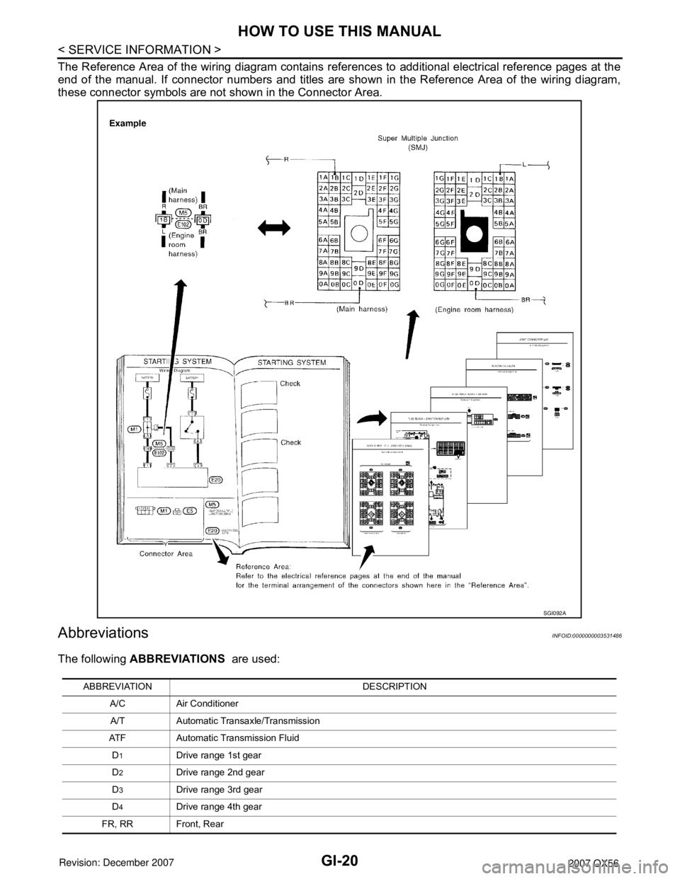
The Reference Area of the wiring diagram contains references to additional electrical reference pages at the
end of the manual. If connector numbers and titles are shown in the Reference Area of the wiring diagram,
these connector symbols are not shown in the Connector Area.
AbbreviationsINFOID:0000000003531486
The following ABBREVIATIONS are used:
SGI092A
ABBREVIATION DESCRIPTION
A/C Air Conditioner
A/T Automatic Transaxle/Transmission
ATF Automatic Transmission Fluid
D
1Drive range 1st gear
D
2Drive range 2nd gear
D
3Drive range 3rd gear
D
4Drive range 4th gear
FR, RR Front, Rear
Page 1991 of 3061
SERVICE INFORMATION FOR ELECTRICAL INCIDENT
GI-25
< SERVICE INFORMATION >
C
D
E
F
G
H
I
J
K
L
MB
GI
N
O
P
How to Perform Efficient Diagnosis for an Electrical IncidentINFOID:0000000003531488
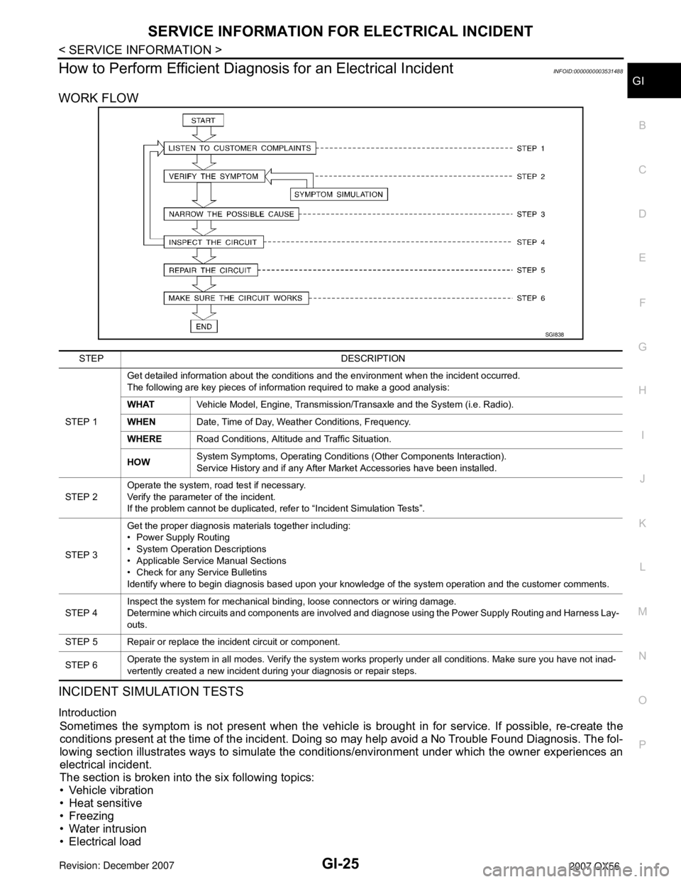
WORK FLOW
INCIDENT SIMULATION TESTS
Introduction
Sometimes the symptom is not present when the vehicle is brought in for service. If possible, re-create the
conditions present at the time of the incident. Doing so may help avoid a No Trouble Found Diagnosis. The fol-
lowing section illustrates ways to simulate the conditions/environment under which the owner experiences an
electrical incident.
The section is broken into the six following topics:
• Vehicle vibration
• Heat sensitive
• Freezing
• Water intrusion
• Electrical load
SGI838
STEP DESCRIPTION
STEP 1Get detailed information about the conditions and the environment when the incident occurred.
The following are key pieces of information required to make a good analysis:
WHATVehicle Model, Engine, Transmission/Transaxle and the System (i.e. Radio).
WHENDate, Time of Day, Weather Conditions, Frequency.
WHERERoad Conditions, Altitude and Traffic Situation.
HOWSystem Symptoms, Operating Conditions (Other Components Interaction).
Service History and if any After Market Accessories have been installed.
STEP 2Operate the system, road test if necessary.
Verify the parameter of the incident.
If the problem cannot be duplicated, refer to “Incident Simulation Tests”.
STEP 3Get the proper diagnosis materials together including:
• Power Supply Routing
• System Operation Descriptions
• Applicable Service Manual Sections
• Check for any Service Bulletins
Identify where to begin diagnosis based upon your knowledge of the system operation and the customer comments.
STEP 4Inspect the system for mechanical binding, loose connectors or wiring damage.
Determine which circuits and components are involved and diagnose using the Power Supply Routing and Harness Lay-
outs.
STEP 5 Repair or replace the incident circuit or component.
STEP 6Operate the system in all modes. Verify the system works properly under all conditions. Make sure you have not inad-
vertently created a new incident during your diagnosis or repair steps.
Page 1993 of 3061
SERVICE INFORMATION FOR ELECTRICAL INCIDENT
GI-27
< SERVICE INFORMATION >
C
D
E
F
G
H
I
J
K
L
MB
GI
N
O
P
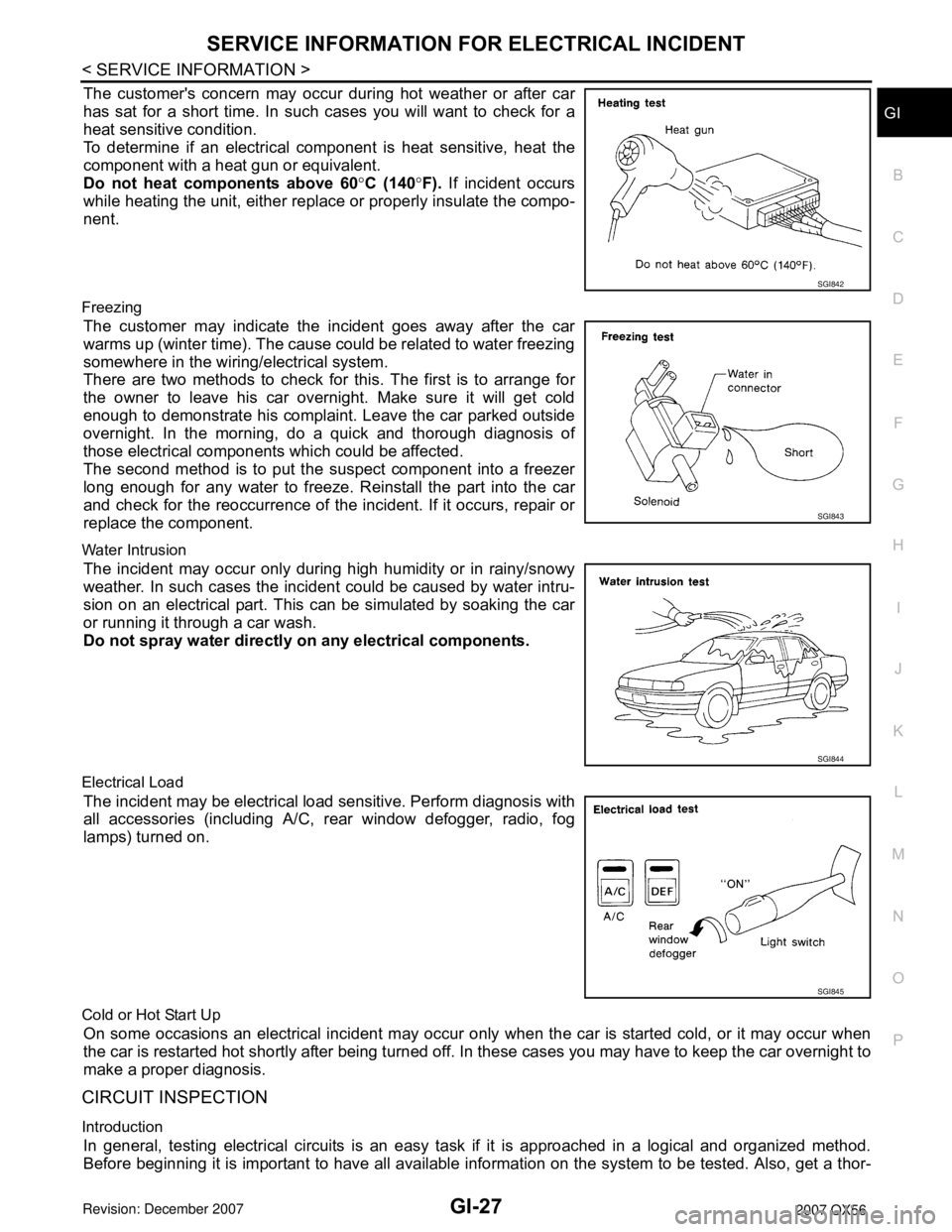
The customer's concern may occur during hot weather or after car
has sat for a short time. In such cases you will want to check for a
heat sensitive condition.
To determine if an electrical component is heat sensitive, heat the
component with a heat gun or equivalent.
Do not heat components above 60°C (140°F). If incident occurs
while heating the unit, either replace or properly insulate the compo-
nent.
Freezing
The customer may indicate the incident goes away after the car
warms up (winter time). The cause could be related to water freezing
somewhere in the wiring/electrical system.
There are two methods to check for this. The first is to arrange for
the owner to leave his car overnight. Make sure it will get cold
enough to demonstrate his complaint. Leave the car parked outside
overnight. In the morning, do a quick and thorough diagnosis of
those electrical components which could be affected.
The second method is to put the suspect component into a freezer
long enough for any water to freeze. Reinstall the part into the car
and check for the reoccurrence of the incident. If it occurs, repair or
replace the component.
Water Intrusion
The incident may occur only during high humidity or in rainy/snowy
weather. In such cases the incident could be caused by water intru-
sion on an electrical part. This can be simulated by soaking the car
or running it through a car wash.
Do not spray water directly on any electrical components.
Electrical Load
The incident may be electrical load sensitive. Perform diagnosis with
all accessories (including A/C, rear window defogger, radio, fog
lamps) turned on.
Cold or Hot Start Up
On some occasions an electrical incident may occur only when the car is started cold, or it may occur when
the car is restarted hot shortly after being turned off. In these cases you may have to keep the car overnight to
make a proper diagnosis.
CIRCUIT INSPECTION
Introduction
In general, testing electrical circuits is an easy task if it is approached in a logical and organized method.
Before beginning it is important to have all available information on the system to be tested. Also, get a thor-
SGI842
SGI843
SGI844
SGI845
Page 2001 of 3061

CONSULT-II CHECKING SYSTEM
GI-35
< SERVICE INFORMATION >
C
D
E
F
G
H
I
J
K
L
MB
GI
N
O
PCONSULT-II CHECKING SYSTEM
DescriptionINFOID:0000000003531490
• CONSULT-II is a hand-held type tester. When it is connected with a diagnostic connector equipped on the
vehicle side, it will communicate with the control unit equipped in the vehicle and then enable various kinds
of diagnostic tests.
• Refer to “CONSULT-II Software Operation Manual” for more information.
Function and System ApplicationINFOID:0000000003531491
x: Applicable.
*1: If equipped.Diagnostic test mode Function
ENGINE
A/T
ICC
*1
ABS
AIR BAG
IPDM E/R
BCM
AUTO DRIVE POS.
REARVIEW CAMERA
AIR LEVELIZER
ALL MODE AWD/4WD
HVAC
NVIS (NATS)
*2
NVIS (NATS BCM OR S/ENT)
*2
Work supportThis mode enables a technician to adjust some devices
faster and more accurately by following the indications on
CONSULT-II.xxxx - - xxxxx - - -
Self-diagnostic Self-diagnostic can be performed quickly. ----x---------
Self-diagnostic results Self-diagnostic results can be read and erased quickly. xxxx - xxx - xxxxx
Trouble diagnostic
recordCurrent self-diagnostic results and all trouble diagnostic
records previously stored can be read.--- - x---------
Data monitor Input/Output data in the ECM can be read. xxxx - x - xxxxx - -
Data monitor (spec) Data monitor specification can be read. x-------------
CAN diagnosis support
monitorThe communication condition of CAN communication line
can be read.xxxx - xxx - - xx - -
Active testDiagnostic Test Mode in which CONSULT-II drives some
actuators apart from the ECMs and also shifts some param-
eters in a specified range.x-xx-x-x-x----
Function testThis mode can show results of self-diagnosis of ECU with
either “OK” or “NG”. For engines, more practical tests re-
garding sensors/switches and/or actuators are available.xx-xx- --- -----
DTC & SRT confirma-
tionThe results of SRT (System Readiness Test) and the self-
diagnosis status/result can be confirmed.x-------------
DTC work supportThe operating condition to confirm Diagnosis Trouble
Codes can be selected.xx------------
ECM/ECU part number ECM/ECU part number can be read.
xxxx - -xx
xxxx - -
ECU discriminated No.Classification number of a replacement ECU can be read to
prevent an incorrect ECU from being installed.----x---------
Passenger Airbag Displays the STATUS (readiness) of the front passenger air
bag.----x---------
Configuration Sets control module parameters to match vehicle options. ------x-------
PIN read
*3This mode shows the BCM-specific 5-digit code. -------------x
Control unit
initialization
*3All registered ignition key IDs in NATS components can be
initialized and new IDs can be registered.------------x-
Page 2024 of 3061
SQUEAK AND RATTLE TROUBLE DIAGNOSIS
GW-5
< SERVICE INFORMATION >
C
D
E
F
G
H
J
K
L
MA
B
GW
N
O
P
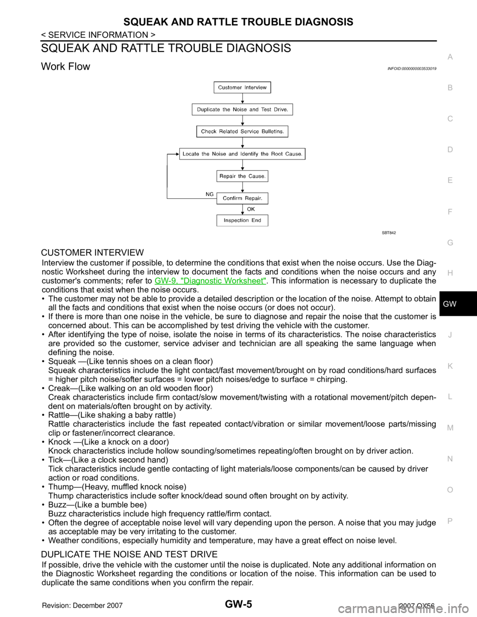
SQUEAK AND RATTLE TROUBLE DIAGNOSIS
Work FlowINFOID:0000000003533019
CUSTOMER INTERVIEW
Interview the customer if possible, to determine the conditions that exist when the noise occurs. Use the Diag-
nostic Worksheet during the interview to document the facts and conditions when the noise occurs and any
customer's comments; refer to GW-9, "
Diagnostic Worksheet". This information is necessary to duplicate the
conditions that exist when the noise occurs.
• The customer may not be able to provide a detailed description or the location of the noise. Attempt to obtain
all the facts and conditions that exist when the noise occurs (or does not occur).
• If there is more than one noise in the vehicle, be sure to diagnose and repair the noise that the customer is
concerned about. This can be accomplished by test driving the vehicle with the customer.
• After identifying the type of noise, isolate the noise in terms of its characteristics. The noise characteristics
are provided so the customer, service adviser and technician are all speaking the same language when
defining the noise.
• Squeak —(Like tennis shoes on a clean floor)
Squeak characteristics include the light contact/fast movement/brought on by road conditions/hard surfaces
= higher pitch noise/softer surfaces = lower pitch noises/edge to surface = chirping.
• Creak—(Like walking on an old wooden floor)
Creak characteristics include firm contact/slow movement/twisting with a rotational movement/pitch depen-
dent on materials/often brought on by activity.
• Rattle—(Like shaking a baby rattle)
Rattle characteristics include the fast repeated contact/vibration or similar movement/loose parts/missing
clip or fastener/incorrect clearance.
• Knock —(Like a knock on a door)
Knock characteristics include hollow sounding/sometimes repeating/often brought on by driver action.
• Tick—(Like a clock second hand)
Tick characteristics include gentle contacting of light materials/loose components/can be caused by driver
action or road conditions.
• Thump—(Heavy, muffled knock noise)
Thump characteristics include softer knock/dead sound often brought on by activity.
• Buzz—(Like a bumble bee)
Buzz characteristics include high frequency rattle/firm contact.
• Often the degree of acceptable noise level will vary depending upon the person. A noise that you may judge
as acceptable may be very irritating to the customer.
• Weather conditions, especially humidity and temperature, may have a great effect on noise level.
DUPLICATE THE NOISE AND TEST DRIVE
If possible, drive the vehicle with the customer until the noise is duplicated. Note any additional information on
the Diagnostic Worksheet regarding the conditions or location of the noise. This information can be used to
duplicate the same conditions when you confirm the repair.
SBT842