Page 1639 of 3061
EC-556
< SERVICE INFORMATION >
DTC P2118 THROTTLE CONTROL MOTOR
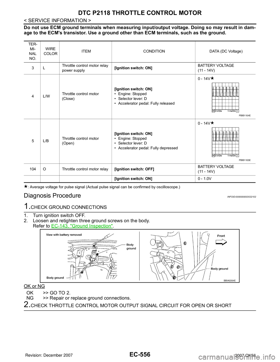
Do not use ECM ground terminals when measuring input/output voltage. Doing so may result in dam-
age to the ECM's transistor. Use a ground other than ECM terminals, such as the ground.
: Average voltage for pulse signal (Actual pulse signal can be confirmed by oscilloscope.)
Diagnosis ProcedureINFOID:0000000003532102
1.CHECK GROUND CONNECTIONS
1. Turn ignition switch OFF.
2. Loosen and retighten three ground screws on the body.
Refer to EC-143, "
Ground Inspection".
OK or NG
OK >> GO TO 2.
NG >> Repair or replace ground connections.
2.CHECK THROTTLE CONTROL MOTOR OUTPUT SIGNAL CIRCUIT FOR OPEN OR SHORT
TER-
MI-
NAL
NO.WIRE
COLORITEM CONDITION DATA (DC Voltage)
3LThrottle control motor relay
power supply[Ignition switch: ON]BATTERY VOLTAGE
(11 - 14V)
4L/WThrottle control motor
(Close)[Ignition switch: ON]
• Engine: Stopped
• Selector lever: D
• Accelerator pedal: Fully released0 - 14V
5L/BThrottle control motor
(Open)[Ignition switch: ON]
• Engine: Stopped
• Selector lever: D
• Accelerator pedal: Fully depressed0 - 14V
104 O Throttle control motor relay[Ignition switch: OFF]BATTERY VOLTAGE
(11 - 14V)
[Ignition switch: ON]0 - 1.0V
PBIB1104E
PBIB1105E
BBIA0354E
Page 1647 of 3061
EC-564
< SERVICE INFORMATION >
DTC P2122, P2123 APP SENSOR
Diagnosis Procedure
INFOID:0000000003532114
1.CHECK GROUND CONNECTIONS
1. Turn ignition switch OFF.
2. Loosen and retighten three ground screws on the body.
Refer to EC-143, "
Ground Inspection" .
OK or NG
OK >> GO TO 2.
NG >> Repair or replace ground connections.
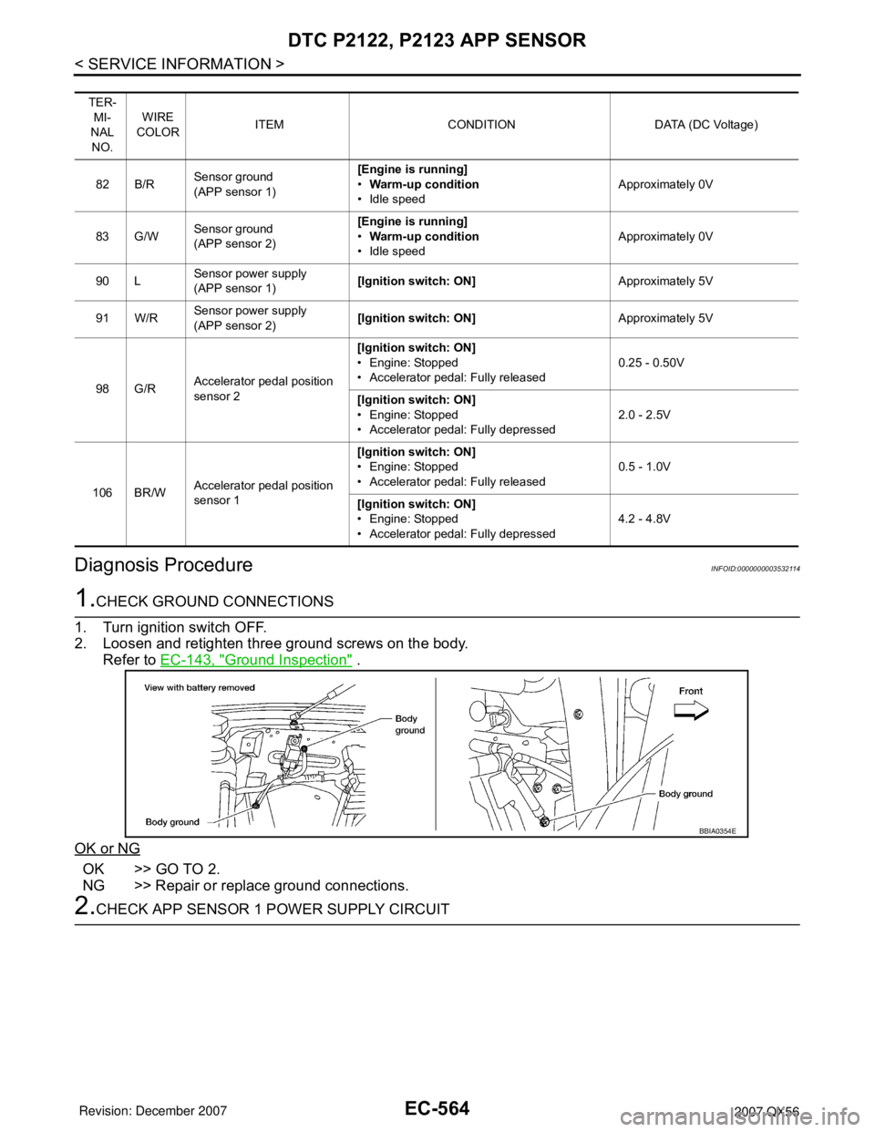
2.CHECK APP SENSOR 1 POWER SUPPLY CIRCUIT
TER-
MI-
NAL
NO.WIRE
COLORITEM CONDITION DATA (DC Voltage)
82 B/RSensor ground
(APP sensor 1)[Engine is running]
•Warm-up condition
• Idle speedApproximately 0V
83 G/WSensor ground
(APP sensor 2)[Engine is running]
•Warm-up condition
• Idle speedApproximately 0V
90 LSensor power supply
(APP sensor 1)[Ignition switch: ON]Approximately 5V
91 W/RSensor power supply
(APP sensor 2)[Ignition switch: ON]Approximately 5V
98 G/RAccelerator pedal position
sensor 2[Ignition switch: ON]
• Engine: Stopped
• Accelerator pedal: Fully released0.25 - 0.50V
[Ignition switch: ON]
• Engine: Stopped
• Accelerator pedal: Fully depressed2.0 - 2.5V
106 BR/WAccelerator pedal position
sensor 1[Ignition switch: ON]
• Engine: Stopped
• Accelerator pedal: Fully released0.5 - 1.0V
[Ignition switch: ON]
• Engine: Stopped
• Accelerator pedal: Fully depressed4.2 - 4.8V
BBIA0354E
Page 1649 of 3061
EC-566
< SERVICE INFORMATION >
DTC P2122, P2123 APP SENSOR
>>INSPECTION END
7.CHECK INTERMITTENT INCIDENT
Refer to EC-138
.
>>INSPECTION END
Component InspectionINFOID:0000000003532115
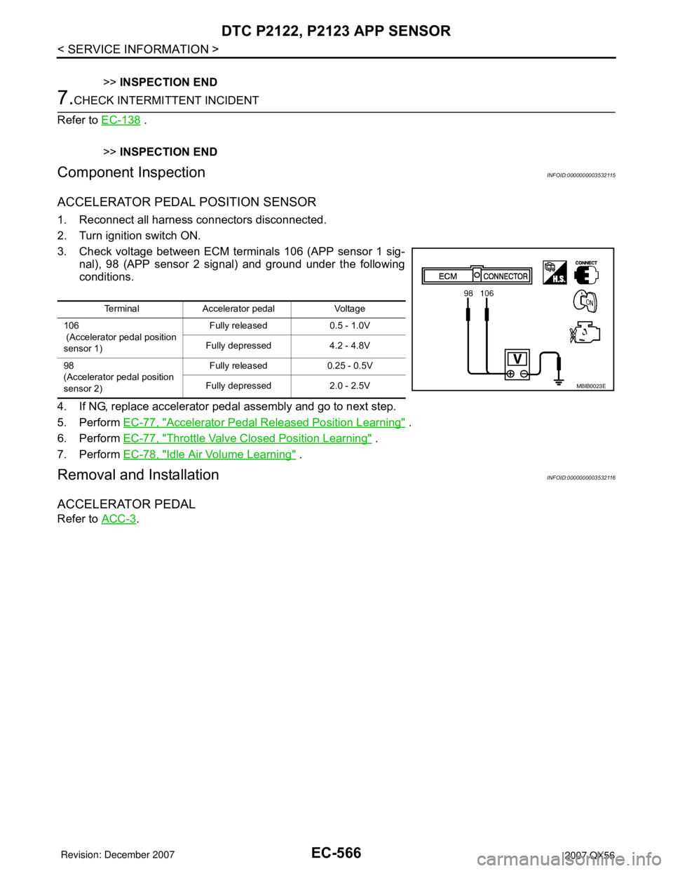
ACCELERATOR PEDAL POSITION SENSOR
1. Reconnect all harness connectors disconnected.
2. Turn ignition switch ON.
3. Check voltage between ECM terminals 106 (APP sensor 1 sig-
nal), 98 (APP sensor 2 signal) and ground under the following
conditions.
4. If NG, replace accelerator pedal assembly and go to next step.
5. Perform EC-77, "
Accelerator Pedal Released Position Learning" .
6. Perform EC-77, "
Throttle Valve Closed Position Learning" .
7. Perform EC-78, "
Idle Air Volume Learning" .
Removal and InstallationINFOID:0000000003532116
ACCELERATOR PEDAL
Refer to ACC-3.
Terminal Accelerator pedal Voltage
106
(Accelerator pedal position
sensor 1)Fully released 0.5 - 1.0V
Fully depressed 4.2 - 4.8V
98
(Accelerator pedal position
sensor 2)Fully released 0.25 - 0.5V
Fully depressed 2.0 - 2.5V
MBIB0023E
Page 1653 of 3061
EC-570
< SERVICE INFORMATION >
DTC P2127, P2128 APP SENSOR
Diagnosis Procedure
INFOID:0000000003532122
1.CHECK GROUND CONNECTIONS
1. Turn ignition switch OFF.
2. Loosen and retighten three ground screws on the body.
Refer to EC-143, "
Ground Inspection" .
OK or NG
OK >> GO TO 2.
NG >> Repair or replace ground connections.
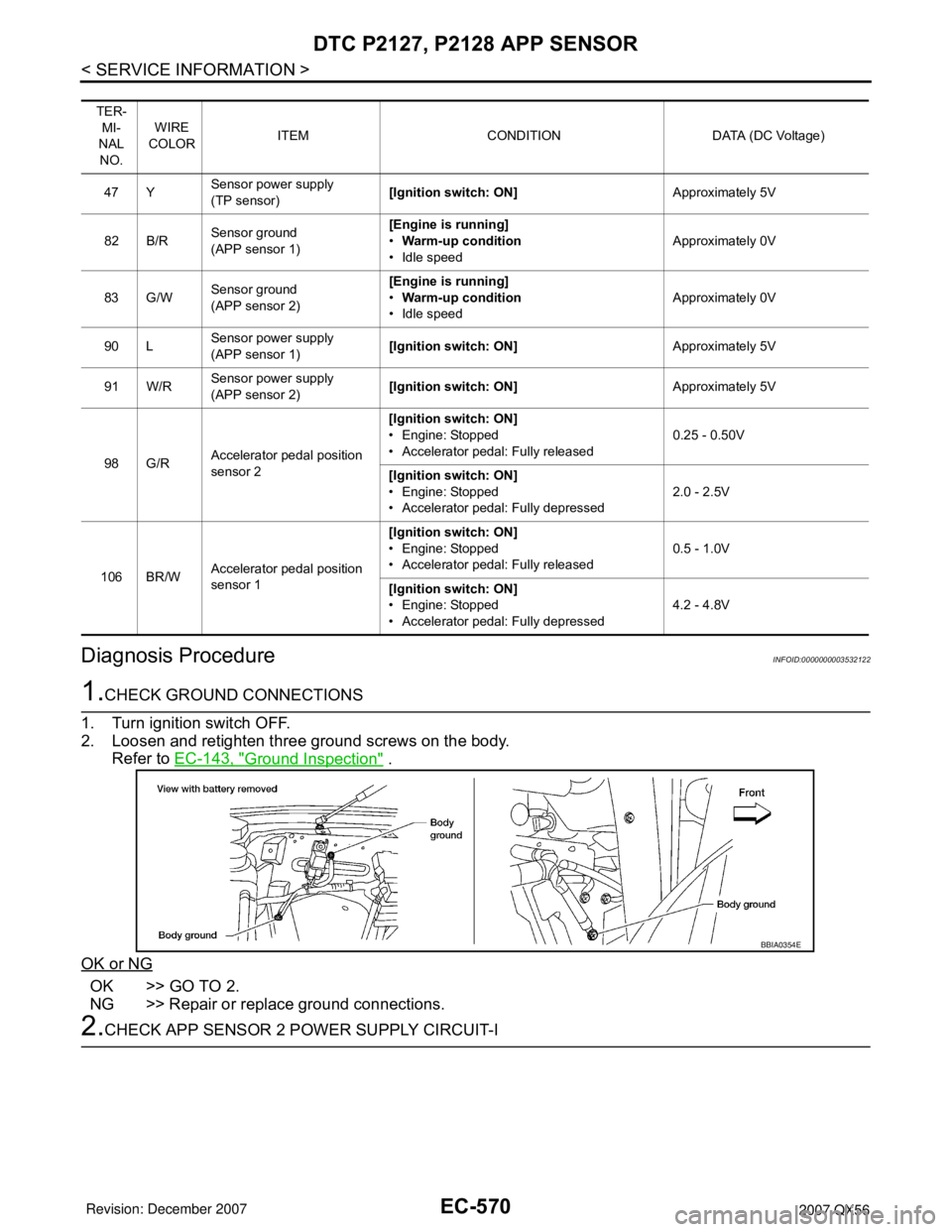
2.CHECK APP SENSOR 2 POWER SUPPLY CIRCUIT-I
TER-
MI-
NAL
NO.WIRE
COLORITEM CONDITION DATA (DC Voltage)
47 YSensor power supply
(TP sensor)[Ignition switch: ON]Approximately 5V
82 B/RSensor ground
(APP sensor 1)[Engine is running]
•Warm-up condition
• Idle speedApproximately 0V
83 G/WSensor ground
(APP sensor 2)[Engine is running]
•Warm-up condition
• Idle speedApproximately 0V
90 LSensor power supply
(APP sensor 1)[Ignition switch: ON]Approximately 5V
91 W/RSensor power supply
(APP sensor 2)[Ignition switch: ON]Approximately 5V
98 G/RAccelerator pedal position
sensor 2[Ignition switch: ON]
• Engine: Stopped
• Accelerator pedal: Fully released0.25 - 0.50V
[Ignition switch: ON]
• Engine: Stopped
• Accelerator pedal: Fully depressed2.0 - 2.5V
106 BR/WAccelerator pedal position
sensor 1[Ignition switch: ON]
• Engine: Stopped
• Accelerator pedal: Fully released0.5 - 1.0V
[Ignition switch: ON]
• Engine: Stopped
• Accelerator pedal: Fully depressed4.2 - 4.8V
BBIA0354E
Page 1656 of 3061
DTC P2127, P2128 APP SENSOR
EC-573
< SERVICE INFORMATION >
C
D
E
F
G
H
I
J
K
L
MA
EC
N
P O
3. Check voltage between ECM terminals 106 (APP sensor 1 sig-
nal), 98 (APP sensor 2 signal) and ground under the following
conditions.
4. If NG, replace accelerator pedal assembly and go to next step.
5. Perform EC-77, "
Accelerator Pedal Released Position Learning" .
6. Perform EC-77, "
Throttle Valve Closed Position Learning" .
7. Perform EC-78, "
Idle Air Volume Learning" .
Removal and InstallationINFOID:0000000003532124
ACCELERATOR PEDAL
Refer to ACC-3.
Terminal Accelerator pedal Voltage
106
(Accelerator pedal position
sensor 1)Fully released 0.5 - 1.0V
Fully depressed 4.2 - 4.8V
98
(Accelerator pedal position
sensor 2)Fully released 0.25 - 0.5V
Fully depressed 2.0 - 2.5V
MBIB0023E
Page 1660 of 3061
DTC P2135 TP SENSOR
EC-577
< SERVICE INFORMATION >
C
D
E
F
G
H
I
J
K
L
MA
EC
N
P O
Diagnosis ProcedureINFOID:0000000003532130
1.CHECK GROUND CONNECTIONS
1. Turn ignition switch OFF.
2. Loosen and retighten three ground screws on the body.
Refer to EC-143, "
Ground Inspection".
OK or NG
OK >> GO TO 2.
NG >> Repair or replace ground connections.
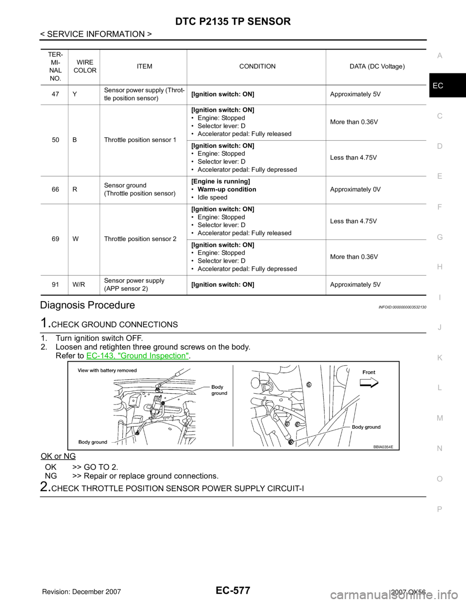
2.CHECK THROTTLE POSITION SENSOR POWER SUPPLY CIRCUIT-I
TER-
MI-
NAL
NO.WIRE
COLORITEM CONDITION DATA (DC Voltage)
47 YSensor power supply (Throt-
tle position sensor)[Ignition switch: ON]Approximately 5V
50 B Throttle position sensor 1[Ignition switch: ON]
• Engine: Stopped
• Selector lever: D
• Accelerator pedal: Fully releasedMore than 0.36V
[Ignition switch: ON]
• Engine: Stopped
• Selector lever: D
• Accelerator pedal: Fully depressedLess than 4.75V
66 RSensor ground
(Throttle position sensor)[Engine is running]
•Warm-up condition
• Idle speedApproximately 0V
69 W Throttle position sensor 2[Ignition switch: ON]
• Engine: Stopped
• Selector lever: D
• Accelerator pedal: Fully releasedLess than 4.75V
[Ignition switch: ON]
• Engine: Stopped
• Selector lever: D
• Accelerator pedal: Fully depressedMore than 0.36V
91 W/RSensor power supply
(APP sensor 2)[Ignition switch: ON]Approximately 5V
BBIA0354E
Page 1667 of 3061
EC-584
< SERVICE INFORMATION >
DTC P2138 APP SENSOR
Diagnosis Procedure
INFOID:0000000003532138
1.CHECK GROUND CONNECTIONS
1. Turn ignition switch OFF.
2. Loosen and retighten three ground screws on the body.
Refer to EC-143, "
Ground Inspection" .
OK or NG
OK >> GO TO 2.
NG >> Repair or replace ground connections.
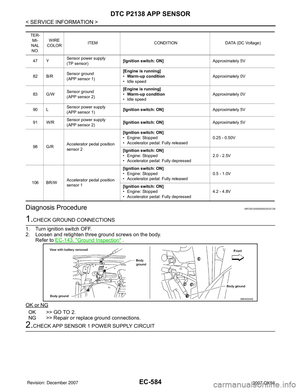
2.CHECK APP SENSOR 1 POWER SUPPLY CIRCUIT
TER-
MI-
NAL
NO.WIRE
COLORITEM CONDITION DATA (DC Voltage)
47 YSensor power supply
(TP sensor)[Ignition switch: ON]Approximately 5V
82 B/RSensor ground
(APP sensor 1)[Engine is running]
•Warm-up condition
• Idle speedApproximately 0V
83 G/WSensor ground
(APP sensor 2)[Engine is running]
•Warm-up condition
• Idle speedApproximately 0V
90 LSensor power supply
(APP sensor 1)[Ignition switch: ON]Approximately 5V
91 W/RSensor power supply
(APP sensor 2)[Ignition switch: ON]Approximately 5V
98 G/RAccelerator pedal position
sensor 2[Ignition switch: ON]
• Engine: Stopped
• Accelerator pedal: Fully released0.25 - 0.50V
[Ignition switch: ON]
• Engine: Stopped
• Accelerator pedal: Fully depressed2.0 - 2.5V
106 BR/WAccelerator pedal position
sensor 1[Ignition switch: ON]
• Engine: Stopped
• Accelerator pedal: Fully released0.5 - 1.0V
[Ignition switch: ON]
• Engine: Stopped
• Accelerator pedal: Fully depressed4.2 - 4.8V
BBIA0354E
Page 1670 of 3061
DTC P2138 APP SENSOR
EC-587
< SERVICE INFORMATION >
C
D
E
F
G
H
I
J
K
L
MA
EC
N
P O
>>INSPECTION END
Component InspectionINFOID:0000000003532139
ACCELERATOR PEDAL POSITION SENSOR
1. Reconnect all harness connectors disconnected.
2. Turn ignition switch ON.
3. Check voltage between ECM terminals 106 (APP sensor 1 sig-
nal), 98 (APP sensor 2 signal) and ground under the following
conditions.
4. If NG, replace accelerator pedal assembly and go to next step.
5. Perform EC-77, "
Accelerator Pedal Released Position Learning" .
6. Perform EC-77, "
Throttle Valve Closed Position Learning" .
7. Perform EC-78, "
Idle Air Volume Learning" .
Removal and InstallationINFOID:0000000003532140
ACCELERATOR PEDAL
Refer to ACC-3 .
Terminal Accelerator pedal Voltage
106
(Accelerator pedal position
sensor 1)Fully released 0.5 - 1.0V
Fully depressed 4.2 - 4.8V
98
(Accelerator pedal position
sensor 2)Fully released 0.25 - 0.5V
Fully depressed 2.0 - 2.5V
MBIB0023E