2007 INFINITI QX56 air condition
[x] Cancel search: air conditionPage 2074 of 3061
POWER WINDOW SYSTEM
GW-55
< SERVICE INFORMATION >
C
D
E
F
G
H
J
K
L
MA
B
GW
N
O
P
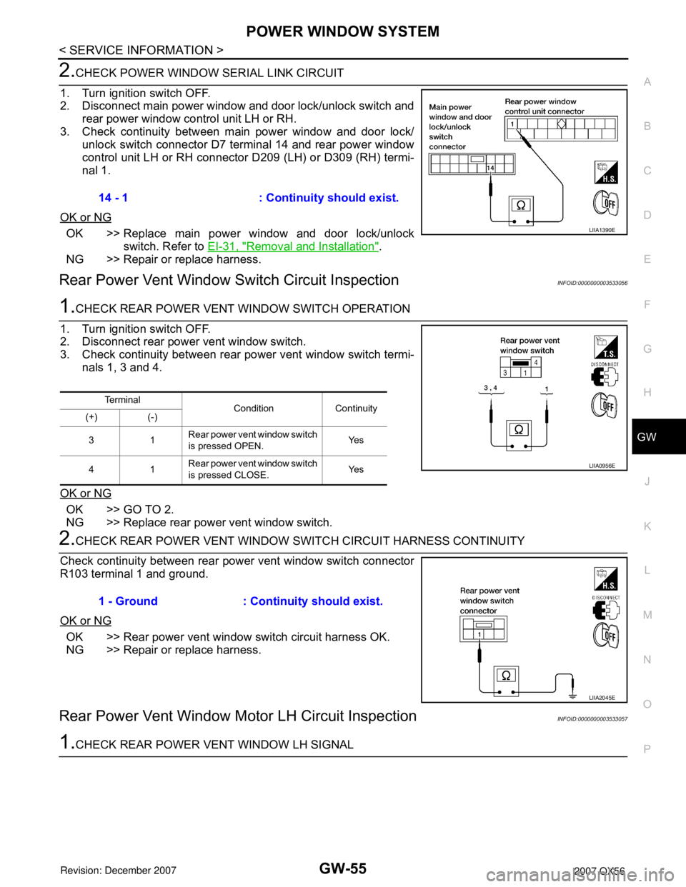
2.CHECK POWER WINDOW SERIAL LINK CIRCUIT
1. Turn ignition switch OFF.
2. Disconnect main power window and door lock/unlock switch and
rear power window control unit LH or RH.
3. Check continuity between main power window and door lock/
unlock switch connector D7 terminal 14 and rear power window
control unit LH or RH connector D209 (LH) or D309 (RH) termi-
nal 1.
OK or NG
OK >> Replace main power window and door lock/unlock
switch. Refer to EI-31, "
Removal and Installation".
NG >> Repair or replace harness.
Rear Power Vent Window Switch Circuit InspectionINFOID:0000000003533056
1.CHECK REAR POWER VENT WINDOW SWITCH OPERATION
1. Turn ignition switch OFF.
2. Disconnect rear power vent window switch.
3. Check continuity between rear power vent window switch termi-
nals 1, 3 and 4.
OK or NG
OK >> GO TO 2.
NG >> Replace rear power vent window switch.
2.CHECK REAR POWER VENT WINDOW SWITCH CIRCUIT HARNESS CONTINUITY
Check continuity between rear power vent window switch connector
R103 terminal 1 and ground.
OK or NG
OK >> Rear power vent window switch circuit harness OK.
NG >> Repair or replace harness.
Rear Power Vent Window Motor LH Circuit InspectionINFOID:0000000003533057
1.CHECK REAR POWER VENT WINDOW LH SIGNAL14 - 1 : Continuity should exist.
LIIA1390E
Te r m i n a l
Condition Continuity
(+) (-)
31Rear power vent window switch
is pressed OPEN.Ye s
41Rear power vent window switch
is pressed CLOSE.Ye s
LIIA0956E
1 - Ground : Continuity should exist.
LIIA2045E
Page 2075 of 3061
GW-56
< SERVICE INFORMATION >
POWER WINDOW SYSTEM
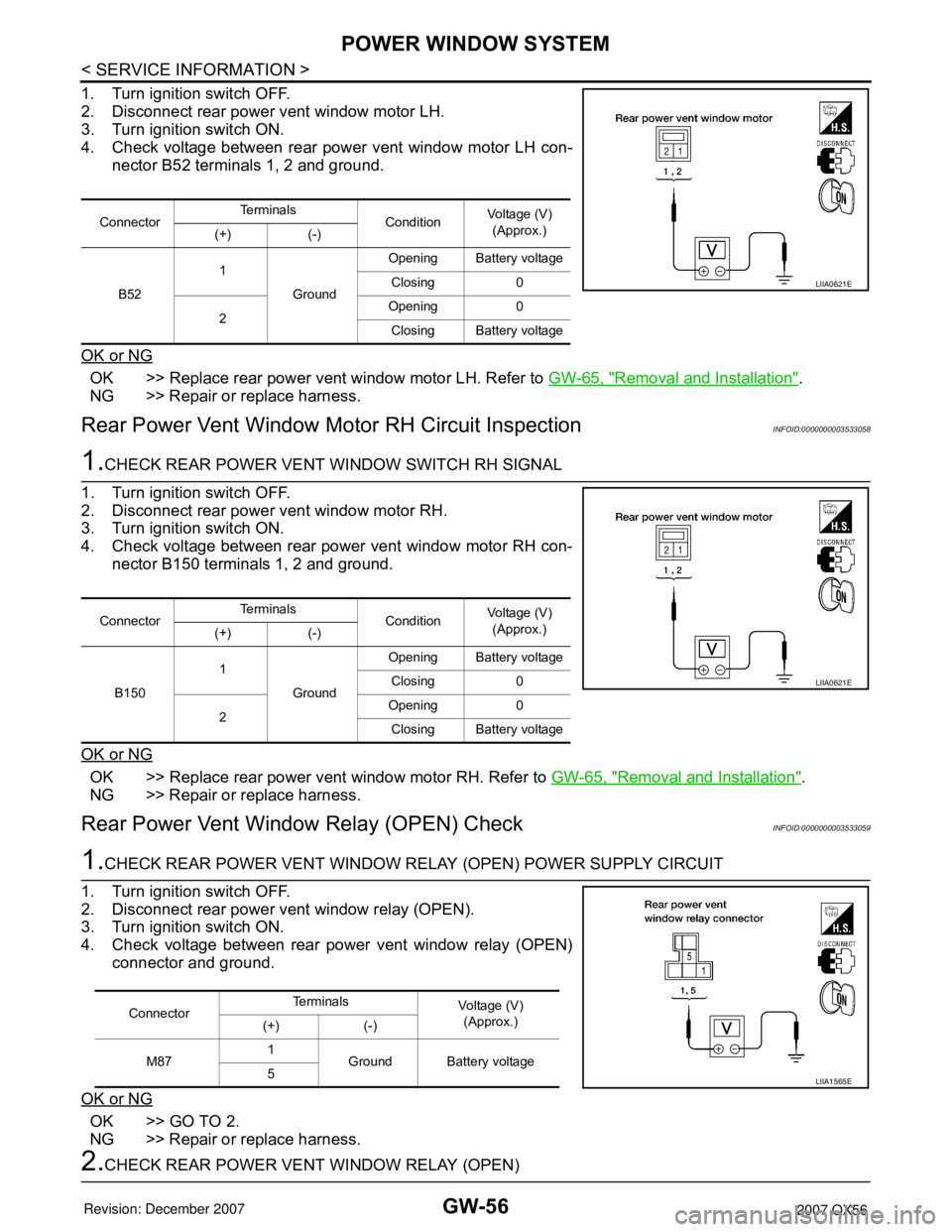
1. Turn ignition switch OFF.
2. Disconnect rear power vent window motor LH.
3. Turn ignition switch ON.
4. Check voltage between rear power vent window motor LH con-
nector B52 terminals 1, 2 and ground.
OK or NG
OK >> Replace rear power vent window motor LH. Refer to GW-65, "Removal and Installation".
NG >> Repair or replace harness.
Rear Power Vent Window Motor RH Circuit InspectionINFOID:0000000003533058
1.CHECK REAR POWER VENT WINDOW SWITCH RH SIGNAL
1. Turn ignition switch OFF.
2. Disconnect rear power vent window motor RH.
3. Turn ignition switch ON.
4. Check voltage between rear power vent window motor RH con-
nector B150 terminals 1, 2 and ground.
OK or NG
OK >> Replace rear power vent window motor RH. Refer to GW-65, "Removal and Installation".
NG >> Repair or replace harness.
Rear Power Vent Window Relay (OPEN) CheckINFOID:0000000003533059
1.CHECK REAR POWER VENT WINDOW RELAY (OPEN) POWER SUPPLY CIRCUIT
1. Turn ignition switch OFF.
2. Disconnect rear power vent window relay (OPEN).
3. Turn ignition switch ON.
4. Check voltage between rear power vent window relay (OPEN)
connector and ground.
OK or NG
OK >> GO TO 2.
NG >> Repair or replace harness.
2.CHECK REAR POWER VENT WINDOW RELAY (OPEN)
ConnectorTe r m i n a l s
ConditionVoltage (V)
(Approx.)
(+) (-)
B521
GroundOpening Battery voltage
Closing 0
2Opening 0
Closing Battery voltage
LIIA0621E
ConnectorTe r m i n a l s
ConditionVoltage (V)
(Approx.)
(+) (-)
B1501
GroundOpening Battery voltage
Closing 0
2Opening 0
Closing Battery voltage
LIIA0621E
ConnectorTe r m i n a l s
Voltage (V)
(Approx.)
(+) (-)
M871
Ground Battery voltage
5
LIIA1565E
Page 2076 of 3061
POWER WINDOW SYSTEM
GW-57
< SERVICE INFORMATION >
C
D
E
F
G
H
J
K
L
MA
B
GW
N
O
P
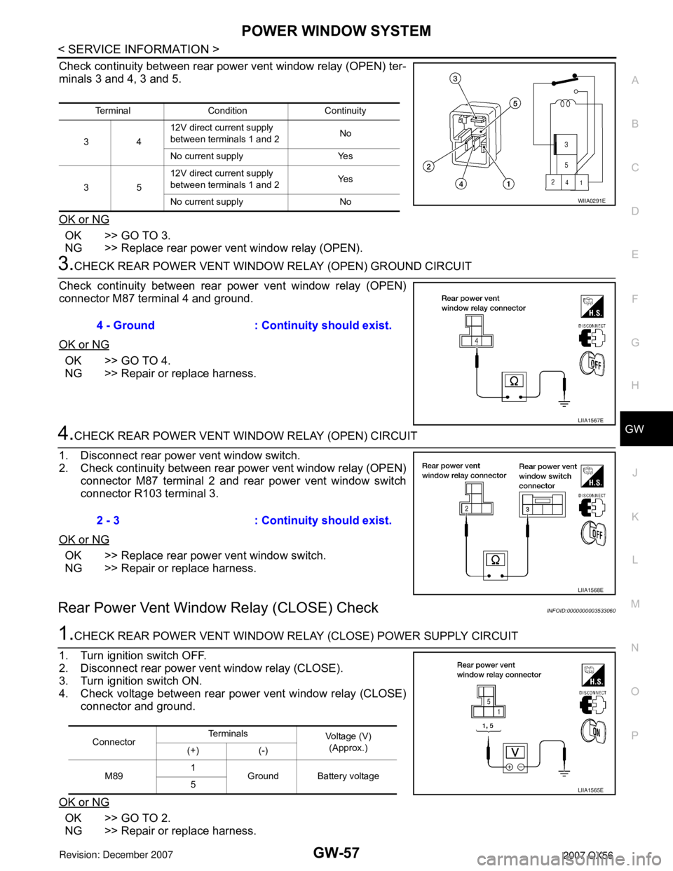
Check continuity between rear power vent window relay (OPEN) ter-
minals 3 and 4, 3 and 5.
OK or NG
OK >> GO TO 3.
NG >> Replace rear power vent window relay (OPEN).
3.CHECK REAR POWER VENT WINDOW RELAY (OPEN) GROUND CIRCUIT
Check continuity between rear power vent window relay (OPEN)
connector M87 terminal 4 and ground.
OK or NG
OK >> GO TO 4.
NG >> Repair or replace harness.
4.CHECK REAR POWER VENT WINDOW RELAY (OPEN) CIRCUIT
1. Disconnect rear power vent window switch.
2. Check continuity between rear power vent window relay (OPEN)
connector M87 terminal 2 and rear power vent window switch
connector R103 terminal 3.
OK or NG
OK >> Replace rear power vent window switch.
NG >> Repair or replace harness.
Rear Power Vent Window Relay (CLOSE) CheckINFOID:0000000003533060
1.CHECK REAR POWER VENT WINDOW RELAY (CLOSE) POWER SUPPLY CIRCUIT
1. Turn ignition switch OFF.
2. Disconnect rear power vent window relay (CLOSE).
3. Turn ignition switch ON.
4. Check voltage between rear power vent window relay (CLOSE)
connector and ground.
OK or NG
OK >> GO TO 2.
NG >> Repair or replace harness.
Terminal Condition Continuity
3412V direct current supply
between terminals 1 and 2No
No current supply Yes
3512V direct current supply
between terminals 1 and 2Ye s
No current supply No
WIIA0291E
4 - Ground : Continuity should exist.
LIIA1567E
2 - 3 : Continuity should exist.
LIIA1568E
ConnectorTe r m i n a l s
Voltage (V)
(Approx.)
(+) (-)
M891
Ground Battery voltage
5
LIIA1565E
Page 2077 of 3061
GW-58
< SERVICE INFORMATION >
POWER WINDOW SYSTEM
2.CHECK REAR POWER VENT WINDOW RELAY (CLOSE)
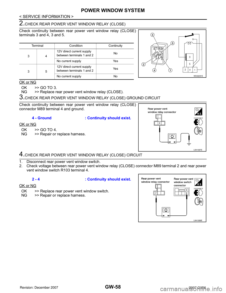
Check continuity between rear power vent window relay (CLOSE)
terminals 3 and 4, 3 and 5.
OK or NG
OK >> GO TO 3.
NG >> Replace rear power vent window relay (CLOSE).
3.CHECK REAR POWER VENT WINDOW RELAY (CLOSE) GROUND CIRCUIT
Check continuity between rear power vent window relay (CLOSE)
connector M89 terminal 4 and ground.
OK or NG
OK >> GO TO 4.
NG >> Repair or replace harness.
4.CHECK REAR POWER VENT WINDOW RELAY (CLOSE) CIRCUIT
1. Disconnect rear power vent window switch.
2. Check voltage between rear power vent window relay (CLOSE) connector M89 terminal 2 and rear power
vent window switch R103 terminal 4.
OK or NG
OK >> Replace rear power vent window switch.
NG >> Repair or replace harness.
Terminal Condition Continuity
3412V direct current supply
between terminals 1 and 2No
No current supply Yes
3512V direct current supply
between terminals 1 and 2Ye s
No current supply No
WIIA0291E
4 - Ground : Continuity should exist.
LIIA1567E
2 - 4 : Continuity should exist.
LIIA1569E
Page 2095 of 3061
GW-76
< SERVICE INFORMATION >
REAR WINDOW DEFOGGER
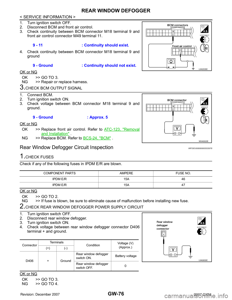
1. Turn ignition switch OFF.
2. Disconnect BCM and front air control.
3. Check continuity between BCM connector M18 terminal 9 and
front air control connector M49 terminal 11.
4. Check continuity between BCM connector M18 terminal 9 and
ground
OK or NG
OK >> GO TO 3.
NG >> Repair or replace harness.
3.CHECK BCM OUTPUT SIGNAL
1. Connect BCM.
2. Turn ignition switch ON.
3. Check voltage between BCM connector M18 terminal 9 and
ground.
OK or NG
OK >> Replace front air control. Refer to ATC-123, "Removal
and Installation" .
NG >> Replace BCM. Refer to BCS-24, "
BCM" .
Rear Window Defogger Circuit InspectionINFOID:0000000003533078
1.CHECK FUSES
Check if any of the following fuses in IPDM E/R are blown.
OK or NG
OK >> GO TO 2.
NG >> If fuse is blown, be sure to eliminate cause of malfunction before installing new fuse.
2.CHECK REAR WINDOW DEFOGGER POWER SUPPLY CIRCUIT
1. Turn ignition switch OFF.
2. Disconnect rear window defogger.
3. Turn ignition switch ON.
4. Check voltage between rear window defogger connector D406
terminal + and ground.
OK or NG
OK >> GO TO 3.
NG >> GO TO 4.9 - 11 : Continuity should exist.
9 - Ground : Continuity should not exist.
LIIA2035E
9 - Ground : Approx. 5
WIIA0523E
COMPONENT PARTS AMPERE FUSE NO.
IPDM E/R 15A 46
IPDM E/R 15A 47
ConnectorTe r m i n a l s
ConditionVoltage (V)
(Approx.)
(+) (-)
D406 + GroundRear window defogger
switch ON. Battery voltage
Rear window defogger
switch OFF.0
LIIA0655E
Page 2096 of 3061
REAR WINDOW DEFOGGER
GW-77
< SERVICE INFORMATION >
C
D
E
F
G
H
J
K
L
MA
B
GW
N
O
P
3.CHECK REAR WINDOW DEFOGGER GROUND CIRCUIT
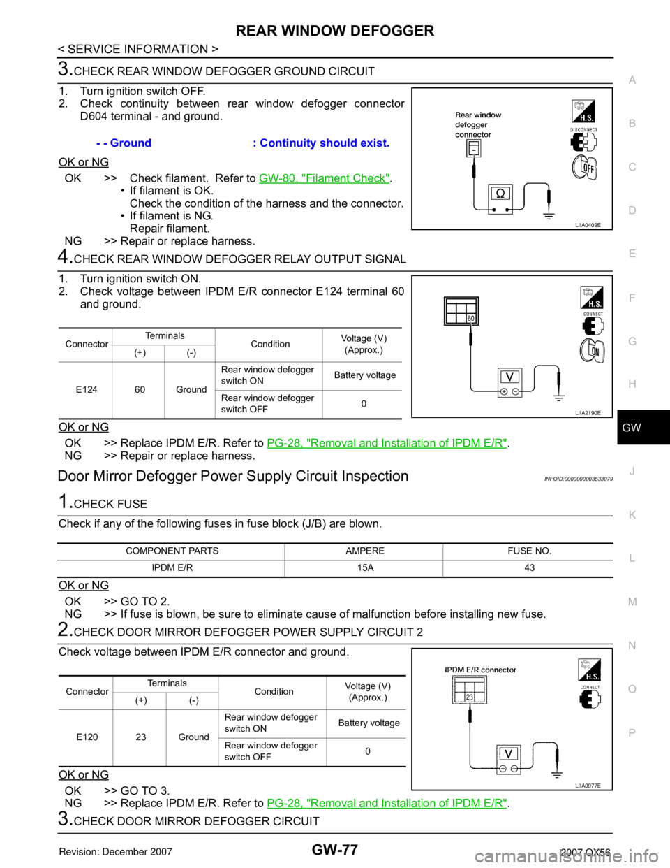
1. Turn ignition switch OFF.
2. Check continuity between rear window defogger connector
D604 terminal - and ground.
OK or NG
OK >> Check filament. Refer to GW-80, "Filament Check".
• If filament is OK.
Check the condition of the harness and the connector.
• If filament is NG.
Repair filament.
NG >> Repair or replace harness.
4.CHECK REAR WINDOW DEFOGGER RELAY OUTPUT SIGNAL
1. Turn ignition switch ON.
2. Check voltage between IPDM E/R connector E124 terminal 60
and ground.
OK or NG
OK >> Replace IPDM E/R. Refer to PG-28, "Removal and Installation of IPDM E/R".
NG >> Repair or replace harness.
Door Mirror Defogger Power Supply Circuit InspectionINFOID:0000000003533079
1.CHECK FUSE
Check if any of the following fuses in fuse block (J/B) are blown.
OK or NG
OK >> GO TO 2.
NG >> If fuse is blown, be sure to eliminate cause of malfunction before installing new fuse.
2.CHECK DOOR MIRROR DEFOGGER POWER SUPPLY CIRCUIT 2
Check voltage between IPDM E/R connector and ground.
OK or NG
OK >> GO TO 3.
NG >> Replace IPDM E/R. Refer to PG-28, "
Removal and Installation of IPDM E/R".
3.CHECK DOOR MIRROR DEFOGGER CIRCUIT- - Ground : Continuity should exist.
LIIA0409E
ConnectorTe r m i n a l s
ConditionVoltage (V)
(Approx.)
(+) (-)
E124 60 GroundRear window defogger
switch ON Battery voltage
Rear window defogger
switch OFF0
LIIA2190E
COMPONENT PARTS AMPERE FUSE NO.
IPDM E/R 15A 43
ConnectorTe r m i n a l s
ConditionVoltage (V)
(Approx.)
(+) (-)
E120 23 GroundRear window defogger
switch ON Battery voltage
Rear window defogger
switch OFF0
LIIA0977E
Page 2097 of 3061
GW-78
< SERVICE INFORMATION >
REAR WINDOW DEFOGGER
1. Turn ignition switch OFF.
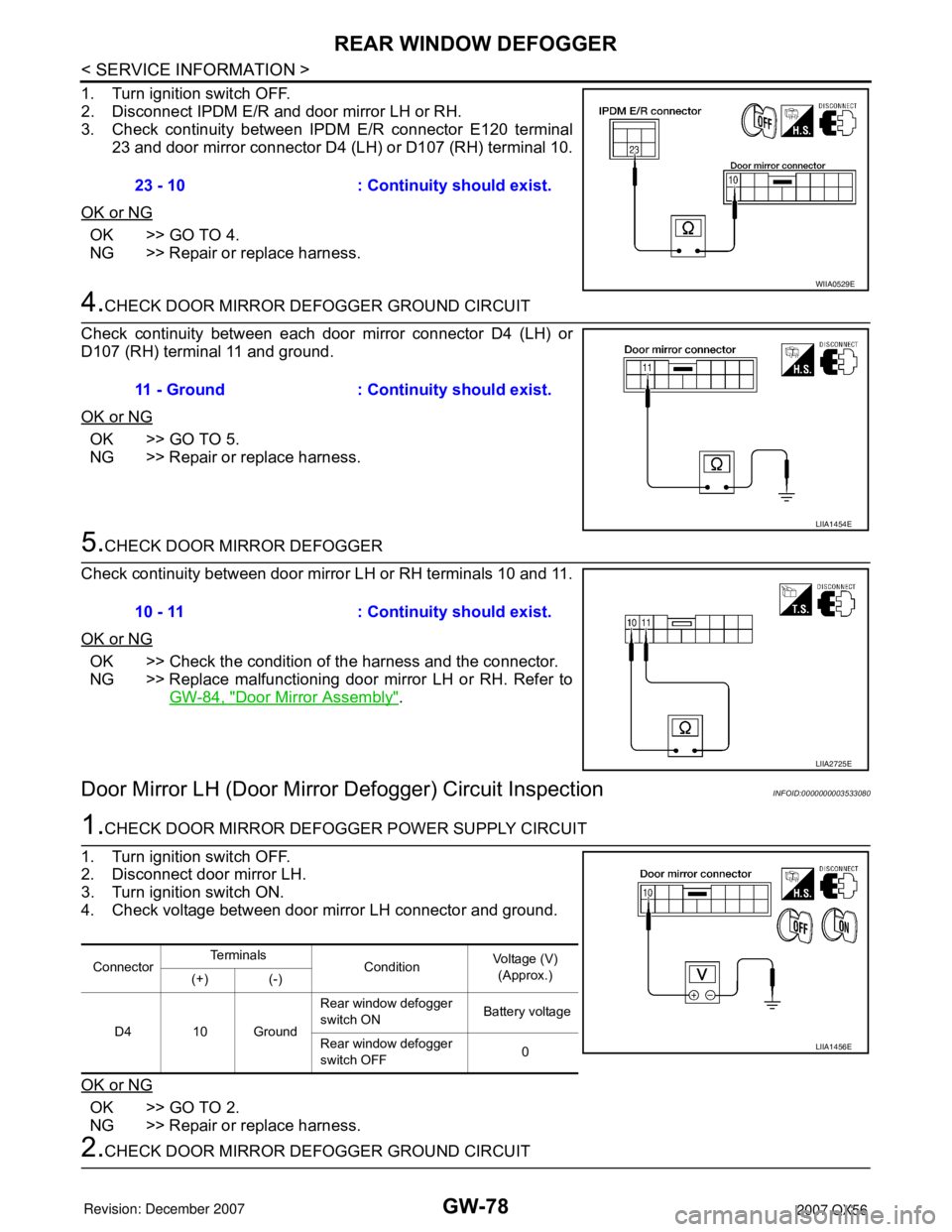
2. Disconnect IPDM E/R and door mirror LH or RH.
3. Check continuity between IPDM E/R connector E120 terminal
23 and door mirror connector D4 (LH) or D107 (RH) terminal 10.
OK or NG
OK >> GO TO 4.
NG >> Repair or replace harness.
4.CHECK DOOR MIRROR DEFOGGER GROUND CIRCUIT
Check continuity between each door mirror connector D4 (LH) or
D107 (RH) terminal 11 and ground.
OK or NG
OK >> GO TO 5.
NG >> Repair or replace harness.
5.CHECK DOOR MIRROR DEFOGGER
Check continuity between door mirror LH or RH terminals 10 and 11.
OK or NG
OK >> Check the condition of the harness and the connector.
NG >> Replace malfunctioning door mirror LH or RH. Refer to
GW-84, "
Door Mirror Assembly".
Door Mirror LH (Door Mirror Defogger) Circuit InspectionINFOID:0000000003533080
1.CHECK DOOR MIRROR DEFOGGER POWER SUPPLY CIRCUIT
1. Turn ignition switch OFF.
2. Disconnect door mirror LH.
3. Turn ignition switch ON.
4. Check voltage between door mirror LH connector and ground.
OK or NG
OK >> GO TO 2.
NG >> Repair or replace harness.
2.CHECK DOOR MIRROR DEFOGGER GROUND CIRCUIT23 - 10 : Continuity should exist.
WIIA0529E
11 - Ground : Continuity should exist.
LIIA1454E
10 - 11 : Continuity should exist.
LIIA2725E
ConnectorTe r m i n a l s
ConditionVoltage (V)
(Approx.)
(+) (-)
D4 10 GroundRear window defogger
switch ON Battery voltage
Rear window defogger
switch OFF0
LIIA1456E
Page 2098 of 3061

REAR WINDOW DEFOGGER
GW-79
< SERVICE INFORMATION >
C
D
E
F
G
H
J
K
L
MA
B
GW
N
O
P
1. Turn ignition switch OFF.
2. Check continuity between door mirror LH connector D4 terminal
11 and ground.
OK or NG
OK >> GO TO 3.
NG >> Repair or replace harness.
3.CHECK DOOR MIRROR DEFOGGER
Check continuity between door mirror LH terminals 10 and 11.
OK or NG
OK >> Repair or replace harness.
NG >> Replace door mirror LH. Refer to GW-84, "
Door Mirror
Assembly".
Door Mirror RH (Door Mirror Defogger) Circuit InspectionINFOID:0000000003533081
1.CHECK DOOR MIRROR DEFOGGER POWER SUPPLY CIRCUIT
1. Turn ignition switch OFF.
2. Disconnect door mirror RH.
3. Turn ignition switch ON.
4. Check voltage between door mirror RH connector and ground.
OK or NG
OK >> GO TO 2.
NG >> Repair or replace harness.
2.CHECK DOOR MIRROR DEFOGGER GROUND CIRCUIT
1. Turn ignition switch OFF.
2. Check continuity between door mirror RH connector D107 termi-
nal 11 and ground.
OK or NG
OK >> GO TO 3.
NG >> Repair or replace harness.
3.CHECK DOOR MIRROR DEFOGGER 11 - Ground : Continuity should exist.
LIIA1458E
10 - 11 : Continuity should exist.
LIIA2725E
ConnectorTe r m i n a l s
ConditionVoltage (V)
(Approx.)
(+) (-)
D107 10 GroundRear window defogger
switch ON Battery voltage
Rear window defogger
switch OFF0
LIIA1456E
11 - Ground : Continuity should exist.
LIIA1458E