Page 1639 of 3061
EC-556
< SERVICE INFORMATION >
DTC P2118 THROTTLE CONTROL MOTOR
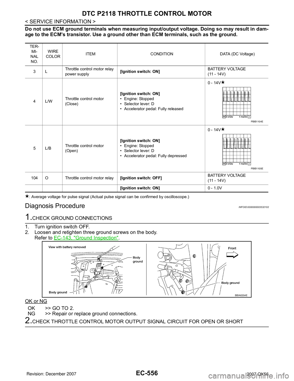
Do not use ECM ground terminals when measuring input/output voltage. Doing so may result in dam-
age to the ECM's transistor. Use a ground other than ECM terminals, such as the ground.
: Average voltage for pulse signal (Actual pulse signal can be confirmed by oscilloscope.)
Diagnosis ProcedureINFOID:0000000003532102
1.CHECK GROUND CONNECTIONS
1. Turn ignition switch OFF.
2. Loosen and retighten three ground screws on the body.
Refer to EC-143, "
Ground Inspection".
OK or NG
OK >> GO TO 2.
NG >> Repair or replace ground connections.
2.CHECK THROTTLE CONTROL MOTOR OUTPUT SIGNAL CIRCUIT FOR OPEN OR SHORT
TER-
MI-
NAL
NO.WIRE
COLORITEM CONDITION DATA (DC Voltage)
3LThrottle control motor relay
power supply[Ignition switch: ON]BATTERY VOLTAGE
(11 - 14V)
4L/WThrottle control motor
(Close)[Ignition switch: ON]
• Engine: Stopped
• Selector lever: D
• Accelerator pedal: Fully released0 - 14V
5L/BThrottle control motor
(Open)[Ignition switch: ON]
• Engine: Stopped
• Selector lever: D
• Accelerator pedal: Fully depressed0 - 14V
104 O Throttle control motor relay[Ignition switch: OFF]BATTERY VOLTAGE
(11 - 14V)
[Ignition switch: ON]0 - 1.0V
PBIB1104E
PBIB1105E
BBIA0354E
Page 1643 of 3061
EC-560
< SERVICE INFORMATION >
DTC P2119 ELECTRIC THROTTLE CONTROL ACTUATOR
Follow the procedure “With CONSULT-II” above.
PROCEDURE FOR MALFUNCTION C
With CONSULT-II
1. Turn ignition switch ON and wait at least 1 second.
2. Select “DATA MONITOR” mode with CONSULT-II.
3. Shift selector lever to D position and wait at least 3 seconds.
4. Shift selector lever to P position.
5. Start engine and let it idle for 3 seconds.
6. If DTC is detected, go to EC-560, "
Diagnosis Procedure".
With GST
Follow the procedure “With CONSULT-II” above.
Diagnosis ProcedureINFOID:0000000003532108
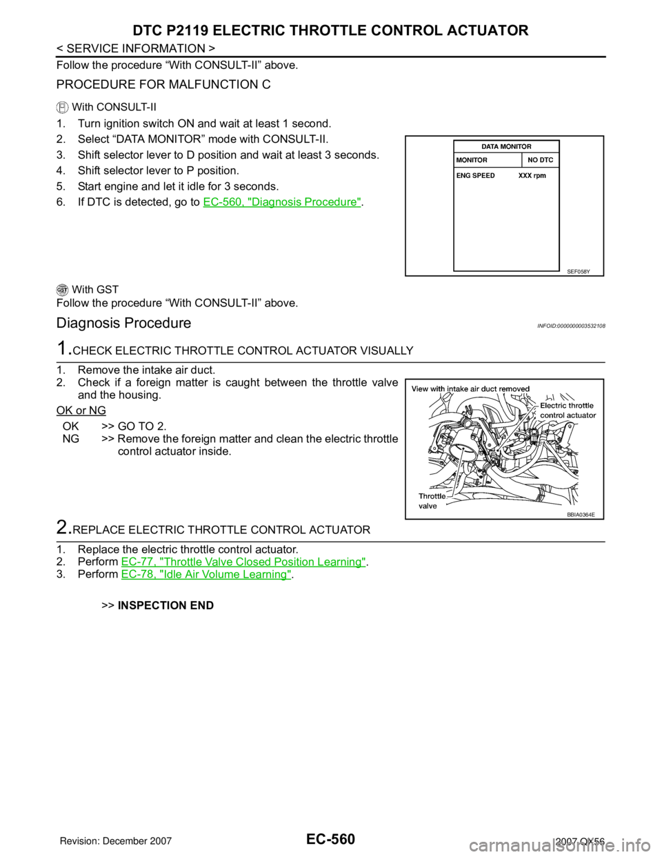
1.CHECK ELECTRIC THROTTLE CONTROL ACTUATOR VISUALLY
1. Remove the intake air duct.
2. Check if a foreign matter is caught between the throttle valve
and the housing.
OK or NG
OK >> GO TO 2.
NG >> Remove the foreign matter and clean the electric throttle
control actuator inside.
2.REPLACE ELECTRIC THROTTLE CONTROL ACTUATOR
1. Replace the electric throttle control actuator.
2. Perform EC-77, "
Throttle Valve Closed Position Learning".
3. Perform EC-78, "
Idle Air Volume Learning".
>>INSPECTION END
SEF058Y
BBIA0364E
Page 1647 of 3061
EC-564
< SERVICE INFORMATION >
DTC P2122, P2123 APP SENSOR
Diagnosis Procedure
INFOID:0000000003532114
1.CHECK GROUND CONNECTIONS
1. Turn ignition switch OFF.
2. Loosen and retighten three ground screws on the body.
Refer to EC-143, "
Ground Inspection" .
OK or NG
OK >> GO TO 2.
NG >> Repair or replace ground connections.
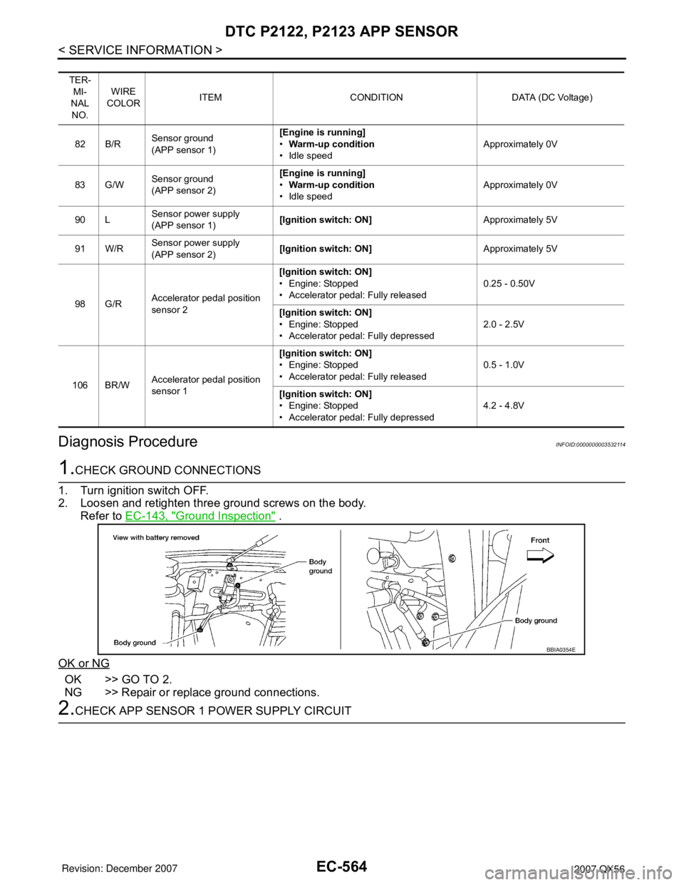
2.CHECK APP SENSOR 1 POWER SUPPLY CIRCUIT
TER-
MI-
NAL
NO.WIRE
COLORITEM CONDITION DATA (DC Voltage)
82 B/RSensor ground
(APP sensor 1)[Engine is running]
•Warm-up condition
• Idle speedApproximately 0V
83 G/WSensor ground
(APP sensor 2)[Engine is running]
•Warm-up condition
• Idle speedApproximately 0V
90 LSensor power supply
(APP sensor 1)[Ignition switch: ON]Approximately 5V
91 W/RSensor power supply
(APP sensor 2)[Ignition switch: ON]Approximately 5V
98 G/RAccelerator pedal position
sensor 2[Ignition switch: ON]
• Engine: Stopped
• Accelerator pedal: Fully released0.25 - 0.50V
[Ignition switch: ON]
• Engine: Stopped
• Accelerator pedal: Fully depressed2.0 - 2.5V
106 BR/WAccelerator pedal position
sensor 1[Ignition switch: ON]
• Engine: Stopped
• Accelerator pedal: Fully released0.5 - 1.0V
[Ignition switch: ON]
• Engine: Stopped
• Accelerator pedal: Fully depressed4.2 - 4.8V
BBIA0354E
Page 1653 of 3061
EC-570
< SERVICE INFORMATION >
DTC P2127, P2128 APP SENSOR
Diagnosis Procedure
INFOID:0000000003532122
1.CHECK GROUND CONNECTIONS
1. Turn ignition switch OFF.
2. Loosen and retighten three ground screws on the body.
Refer to EC-143, "
Ground Inspection" .
OK or NG
OK >> GO TO 2.
NG >> Repair or replace ground connections.
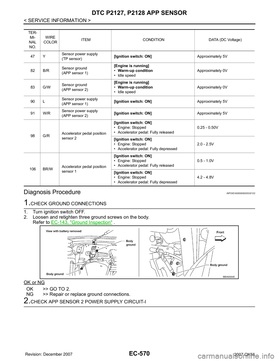
2.CHECK APP SENSOR 2 POWER SUPPLY CIRCUIT-I
TER-
MI-
NAL
NO.WIRE
COLORITEM CONDITION DATA (DC Voltage)
47 YSensor power supply
(TP sensor)[Ignition switch: ON]Approximately 5V
82 B/RSensor ground
(APP sensor 1)[Engine is running]
•Warm-up condition
• Idle speedApproximately 0V
83 G/WSensor ground
(APP sensor 2)[Engine is running]
•Warm-up condition
• Idle speedApproximately 0V
90 LSensor power supply
(APP sensor 1)[Ignition switch: ON]Approximately 5V
91 W/RSensor power supply
(APP sensor 2)[Ignition switch: ON]Approximately 5V
98 G/RAccelerator pedal position
sensor 2[Ignition switch: ON]
• Engine: Stopped
• Accelerator pedal: Fully released0.25 - 0.50V
[Ignition switch: ON]
• Engine: Stopped
• Accelerator pedal: Fully depressed2.0 - 2.5V
106 BR/WAccelerator pedal position
sensor 1[Ignition switch: ON]
• Engine: Stopped
• Accelerator pedal: Fully released0.5 - 1.0V
[Ignition switch: ON]
• Engine: Stopped
• Accelerator pedal: Fully depressed4.2 - 4.8V
BBIA0354E
Page 1660 of 3061
DTC P2135 TP SENSOR
EC-577
< SERVICE INFORMATION >
C
D
E
F
G
H
I
J
K
L
MA
EC
N
P O
Diagnosis ProcedureINFOID:0000000003532130
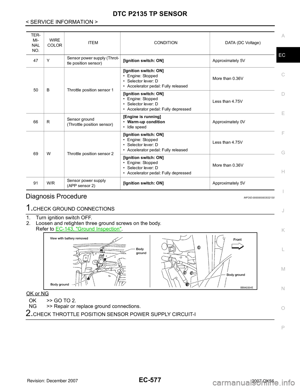
1.CHECK GROUND CONNECTIONS
1. Turn ignition switch OFF.
2. Loosen and retighten three ground screws on the body.
Refer to EC-143, "
Ground Inspection".
OK or NG
OK >> GO TO 2.
NG >> Repair or replace ground connections.
2.CHECK THROTTLE POSITION SENSOR POWER SUPPLY CIRCUIT-I
TER-
MI-
NAL
NO.WIRE
COLORITEM CONDITION DATA (DC Voltage)
47 YSensor power supply (Throt-
tle position sensor)[Ignition switch: ON]Approximately 5V
50 B Throttle position sensor 1[Ignition switch: ON]
• Engine: Stopped
• Selector lever: D
• Accelerator pedal: Fully releasedMore than 0.36V
[Ignition switch: ON]
• Engine: Stopped
• Selector lever: D
• Accelerator pedal: Fully depressedLess than 4.75V
66 RSensor ground
(Throttle position sensor)[Engine is running]
•Warm-up condition
• Idle speedApproximately 0V
69 W Throttle position sensor 2[Ignition switch: ON]
• Engine: Stopped
• Selector lever: D
• Accelerator pedal: Fully releasedLess than 4.75V
[Ignition switch: ON]
• Engine: Stopped
• Selector lever: D
• Accelerator pedal: Fully depressedMore than 0.36V
91 W/RSensor power supply
(APP sensor 2)[Ignition switch: ON]Approximately 5V
BBIA0354E
Page 1667 of 3061
EC-584
< SERVICE INFORMATION >
DTC P2138 APP SENSOR
Diagnosis Procedure
INFOID:0000000003532138
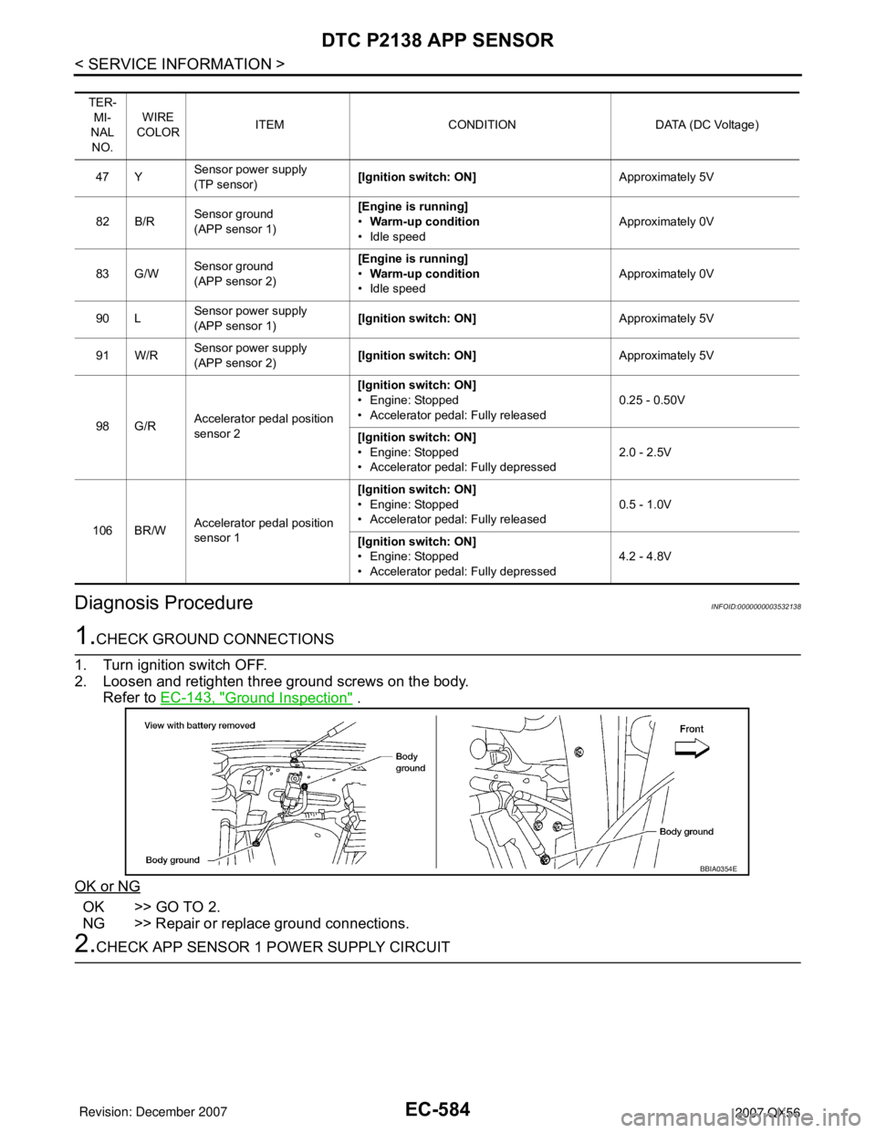
1.CHECK GROUND CONNECTIONS
1. Turn ignition switch OFF.
2. Loosen and retighten three ground screws on the body.
Refer to EC-143, "
Ground Inspection" .
OK or NG
OK >> GO TO 2.
NG >> Repair or replace ground connections.
2.CHECK APP SENSOR 1 POWER SUPPLY CIRCUIT
TER-
MI-
NAL
NO.WIRE
COLORITEM CONDITION DATA (DC Voltage)
47 YSensor power supply
(TP sensor)[Ignition switch: ON]Approximately 5V
82 B/RSensor ground
(APP sensor 1)[Engine is running]
•Warm-up condition
• Idle speedApproximately 0V
83 G/WSensor ground
(APP sensor 2)[Engine is running]
•Warm-up condition
• Idle speedApproximately 0V
90 LSensor power supply
(APP sensor 1)[Ignition switch: ON]Approximately 5V
91 W/RSensor power supply
(APP sensor 2)[Ignition switch: ON]Approximately 5V
98 G/RAccelerator pedal position
sensor 2[Ignition switch: ON]
• Engine: Stopped
• Accelerator pedal: Fully released0.25 - 0.50V
[Ignition switch: ON]
• Engine: Stopped
• Accelerator pedal: Fully depressed2.0 - 2.5V
106 BR/WAccelerator pedal position
sensor 1[Ignition switch: ON]
• Engine: Stopped
• Accelerator pedal: Fully released0.5 - 1.0V
[Ignition switch: ON]
• Engine: Stopped
• Accelerator pedal: Fully depressed4.2 - 4.8V
BBIA0354E
Page 1676 of 3061
DTC P2A00, P2A03 A/F SENSOR 1
EC-593
< SERVICE INFORMATION >
C
D
E
F
G
H
I
J
K
L
MA
EC
N
P O
: Average voltage for pulse signal (Actual pulse signal can be confirmed by oscilloscope.)
Diagnosis ProcedureINFOID:0000000003532146
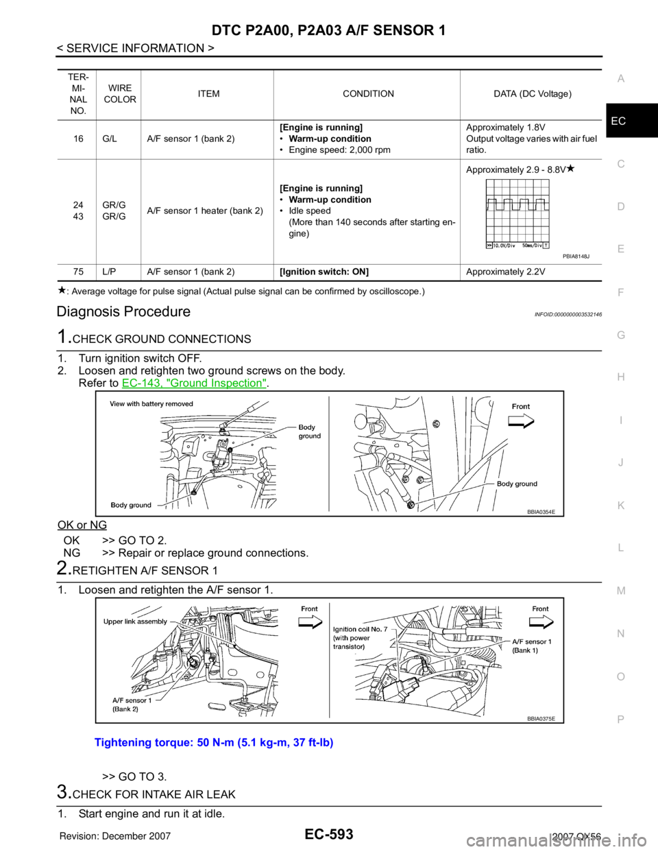
1.CHECK GROUND CONNECTIONS
1. Turn ignition switch OFF.
2. Loosen and retighten two ground screws on the body.
Refer to EC-143, "
Ground Inspection".
OK or NG
OK >> GO TO 2.
NG >> Repair or replace ground connections.
2.RETIGHTEN A/F SENSOR 1
1. Loosen and retighten the A/F sensor 1.
>> GO TO 3.
3.CHECK FOR INTAKE AIR LEAK
1. Start engine and run it at idle.
TER-
MI-
NAL
NO.WIRE
COLORITEM CONDITION DATA (DC Voltage)
16 G/L A/F sensor 1 (bank 2)[Engine is running]
•Warm-up condition
• Engine speed: 2,000 rpmApproximately 1.8V
Output voltage varies with air fuel
ratio.
24
43GR/G
GR/GA/F sensor 1 heater (bank 2)[Engine is running]
•Warm-up condition
• Idle speed
(More than 140 seconds after starting en-
gine)Approximately 2.9 - 8.8V
75 L/P A/F sensor 1 (bank 2)[Ignition switch: ON]Approximately 2.2V
PBIA8148J
BBIA0354E
Tightening torque: 50 N-m (5.1 kg-m, 37 ft-lb)
BBIA0375E
Page 1677 of 3061
EC-594
< SERVICE INFORMATION >
DTC P2A00, P2A03 A/F SENSOR 1
2. Listen for an intake air leak after the mass air flow sensor.
OK or NG
OK >> GO TO 4.
NG >> Repair or replace.
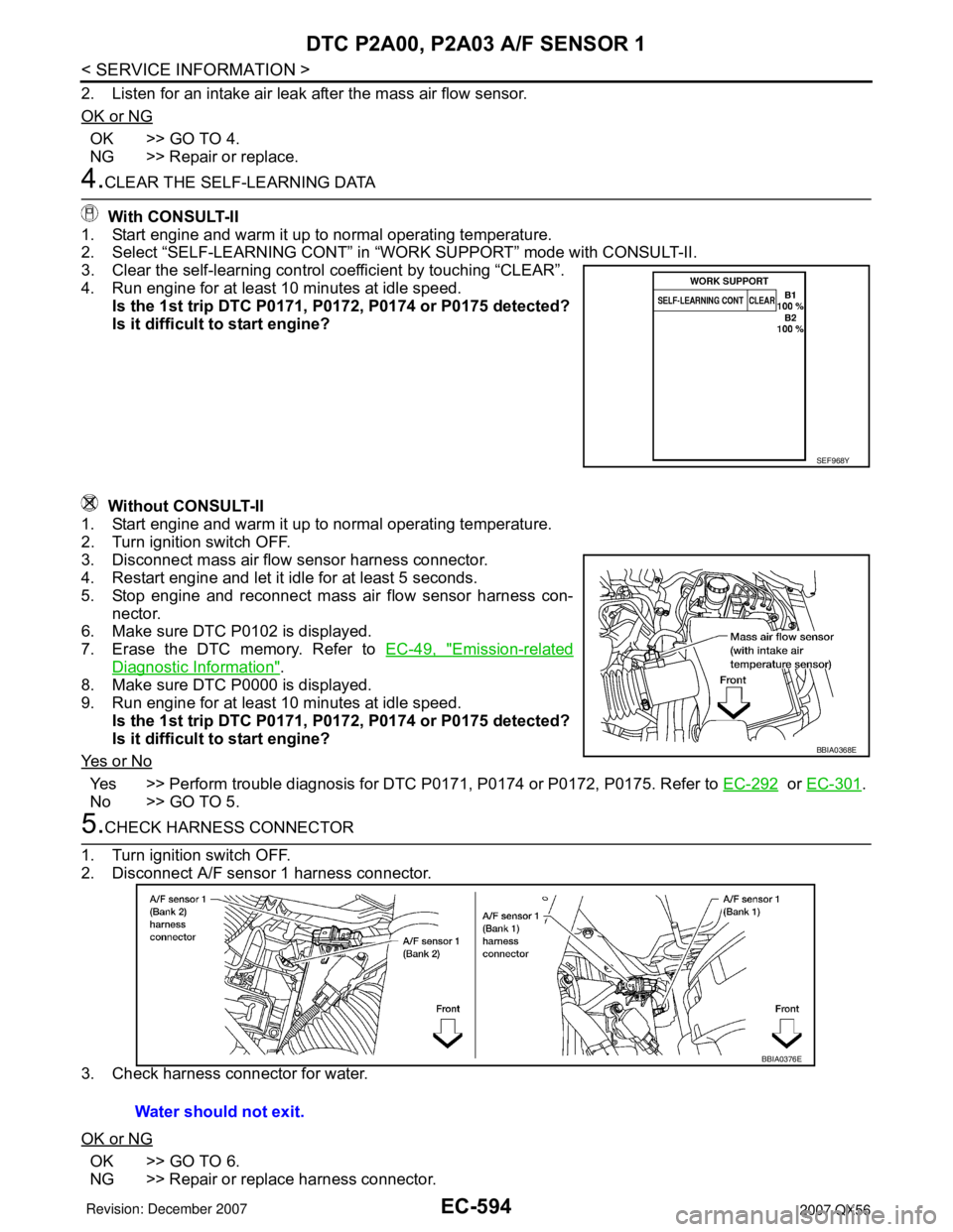
4.CLEAR THE SELF-LEARNING DATA
With CONSULT-II
1. Start engine and warm it up to normal operating temperature.
2. Select “SELF-LEARNING CONT” in “WORK SUPPORT” mode with CONSULT-II.
3. Clear the self-learning control coefficient by touching “CLEAR”.
4. Run engine for at least 10 minutes at idle speed.
Is the 1st trip DTC P0171, P0172, P0174 or P0175 detected?
Is it difficult to start engine?
Without CONSULT-II
1. Start engine and warm it up to normal operating temperature.
2. Turn ignition switch OFF.
3. Disconnect mass air flow sensor harness connector.
4. Restart engine and let it idle for at least 5 seconds.
5. Stop engine and reconnect mass air flow sensor harness con-
nector.
6. Make sure DTC P0102 is displayed.
7. Erase the DTC memory. Refer to EC-49, "
Emission-related
Diagnostic Information".
8. Make sure DTC P0000 is displayed.
9. Run engine for at least 10 minutes at idle speed.
Is the 1st trip DTC P0171, P0172, P0174 or P0175 detected?
Is it difficult to start engine?
Ye s o r N o
Yes >> Perform trouble diagnosis for DTC P0171, P0174 or P0172, P0175. Refer to EC-292 or EC-301.
No >> GO TO 5.
5.CHECK HARNESS CONNECTOR
1. Turn ignition switch OFF.
2. Disconnect A/F sensor 1 harness connector.
3. Check harness connector for water.
OK or NG
OK >> GO TO 6.
NG >> Repair or replace harness connector.
SEF968Y
BBIA0368E
Water should not exit.
BBIA0376E