Page 1465 of 3061
EC-382
< SERVICE INFORMATION >
DTC P0447 EVAP CANISTER VENT CONTROL VALVE
Diagnosis Procedure
INFOID:0000000003531880
1.INSPECTION START
Do you have CONSULT-II?
Ye s o r N o
Ye s > > G O T O 2 .
No >> GO TO 3.
2.CHECK EVAP CANISTER VENT CONTROL VALVE CIRCUIT
With CONSULT-II
1. Turn ignition switch OFF and then turn ON.
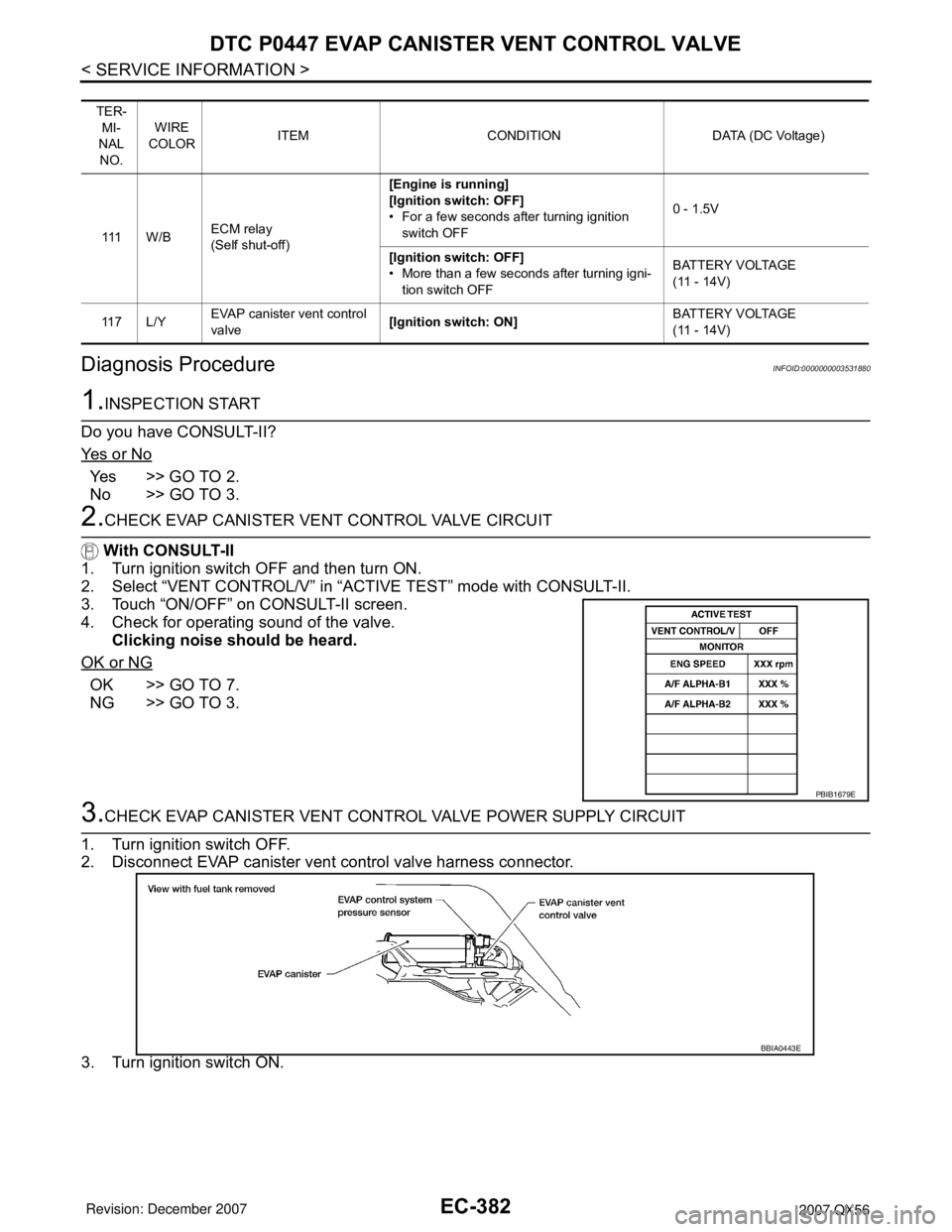
2. Select “VENT CONTROL/V” in “ACTIVE TEST” mode with CONSULT-II.
3. Touch “ON/OFF” on CONSULT-II screen.
4. Check for operating sound of the valve.
Clicking noise should be heard.
OK or NG
OK >> GO TO 7.
NG >> GO TO 3.
3.CHECK EVAP CANISTER VENT CONTROL VALVE POWER SUPPLY CIRCUIT
1. Turn ignition switch OFF.
2. Disconnect EVAP canister vent control valve harness connector.
3. Turn ignition switch ON.
TER-
MI-
NAL
NO.WIRE
COLORITEM CONDITION DATA (DC Voltage)
111 W / BECM relay
(Self shut-off)[Engine is running]
[Ignition switch: OFF]
• For a few seconds after turning ignition
switch OFF0 - 1.5V
[Ignition switch: OFF]
• More than a few seconds after turning igni-
tion switch OFFBATTERY VOLTAGE
(11 - 14V)
11 7 L / YEVAP canister vent control
valve[Ignition switch: ON]BATTERY VOLTAGE
(11 - 14V)
PBIB1679E
BBIA0443E
Page 1472 of 3061
DTC P0448 EVAP CANISTER VENT CONTROL VALVE
EC-389
< SERVICE INFORMATION >
C
D
E
F
G
H
I
J
K
L
MA
EC
N
P O
Diagnosis ProcedureINFOID:0000000003531887
1.CHECK RUBBER TUBE
1. Turn ignition switch OFF.
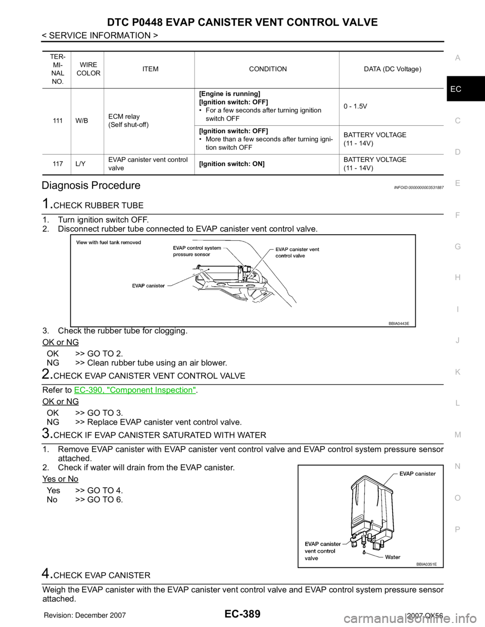
2. Disconnect rubber tube connected to EVAP canister vent control valve.
3. Check the rubber tube for clogging.
OK or NG
OK >> GO TO 2.
NG >> Clean rubber tube using an air blower.
2.CHECK EVAP CANISTER VENT CONTROL VALVE
Refer to EC-390, "
Component Inspection".
OK or NG
OK >> GO TO 3.
NG >> Replace EVAP canister vent control valve.
3.CHECK IF EVAP CANISTER SATURATED WITH WATER
1. Remove EVAP canister with EVAP canister vent control valve and EVAP control system pressure sensor
attached.
2. Check if water will drain from the EVAP canister.
Ye s o r N o
Yes >> GO TO 4.
No >> GO TO 6.
4.CHECK EVAP CANISTER
Weigh the EVAP canister with the EVAP canister vent control valve and EVAP control system pressure sensor
attached.
TER-
MI-
NAL
NO.WIRE
COLORITEM CONDITION DATA (DC Voltage)
111 W / BECM relay
(Self shut-off)[Engine is running]
[Ignition switch: OFF]
• For a few seconds after turning ignition
switch OFF0 - 1.5V
[Ignition switch: OFF]
• More than a few seconds after turning igni-
tion switch OFFBATTERY VOLTAGE
(11 - 14V)
11 7 L / YEVAP canister vent control
valve[Ignition switch: ON]BATTERY VOLTAGE
(11 - 14V)
BBIA0443E
BBIA0351E
Page 1476 of 3061
DTC P0451 EVAP CONTROL SYSTEM PRESSURE SENSOR
EC-393
< SERVICE INFORMATION >
C
D
E
F
G
H
I
J
K
L
MA
EC
N
P O
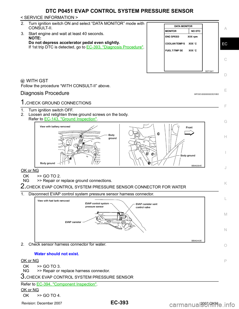
2. Turn ignition switch ON and select “DATA MONITOR” mode with
CONSULT-II.
3. Start engine and wait at least 40 seconds.
NOTE:
Do not depress accelerator pedal even slightly.
If 1st trip DTC is detected, go to EC-393, "
Diagnosis Procedure".
WITH GST
Follow the procedure “WITH CONSULT-II” above.
Diagnosis ProcedureINFOID:0000000003531893
1.CHECK GROUND CONNECTIONS
1. Turn ignition switch OFF.
2. Loosen and retighten three ground screws on the body.
Refer to EC-143, "
Ground Inspection".
OK or NG
OK >> GO TO 2.
NG >> Repair or replace ground connections.
2.CHECK EVAP CONTROL SYSTEM PRESSURE SENSOR CONNECTOR FOR WATER
1. Disconnect EVAP control system pressure sensor harness connector.
2. Check sensor harness connector for water.
OK or NG
OK >> GO TO 3.
NG >> Repair or replace harness connector.
3.CHECK EVAP CONTROL SYSTEM PRESSURE SENSOR
Refer to EC-394, "
Component Inspection".
OK or NG
OK >> GO TO 4.
SEF194Y
BBIA0354E
Water should not exist.
BBIA0443E
Page 1479 of 3061
EC-396
< SERVICE INFORMATION >
DTC P0452 EVAP CONTROL SYSTEM PRESSURE SENSOR
4. Select “DATA MONITOR” mode with CONSULT-II.
5. Make sure that “FUEL T/TMP SE” is more than 0°C (32°F).
6. Start engine and wait at least 20 seconds.
If 1st trip DTC is detected, go to EC-398, "
Diagnosis Procedure".
WITH GST
1. Start engine and warm it up to normal operating temperature.
2. Check that voltage between ECM terminal 107 (Fuel tank tem-
perature sensor signal) and ground is less than 4.2V.
3. Turn ignition switch OFF and wait at least 10 seconds.
4. Start engine and wait at least 20 seconds.
5. Select Service $07 with GST.
If 1st trip DTC is detected, go to EC-398, "
Diagnosis Procedure".
SEF194Y
PBIB1110E
Page 1481 of 3061
EC-398
< SERVICE INFORMATION >
DTC P0452 EVAP CONTROL SYSTEM PRESSURE SENSOR
Diagnosis Procedure
INFOID:0000000003531900
1.CHECK GROUND CONNECTIONS
1. Turn ignition switch OFF.
2. Loosen and retighten three ground screws on the body.
Refer to EC-143, "
Ground Inspection".
OK or NG
OK >> GO TO 2.
NG >> Repair or replace ground connections.
2.CHECK CONNECTOR
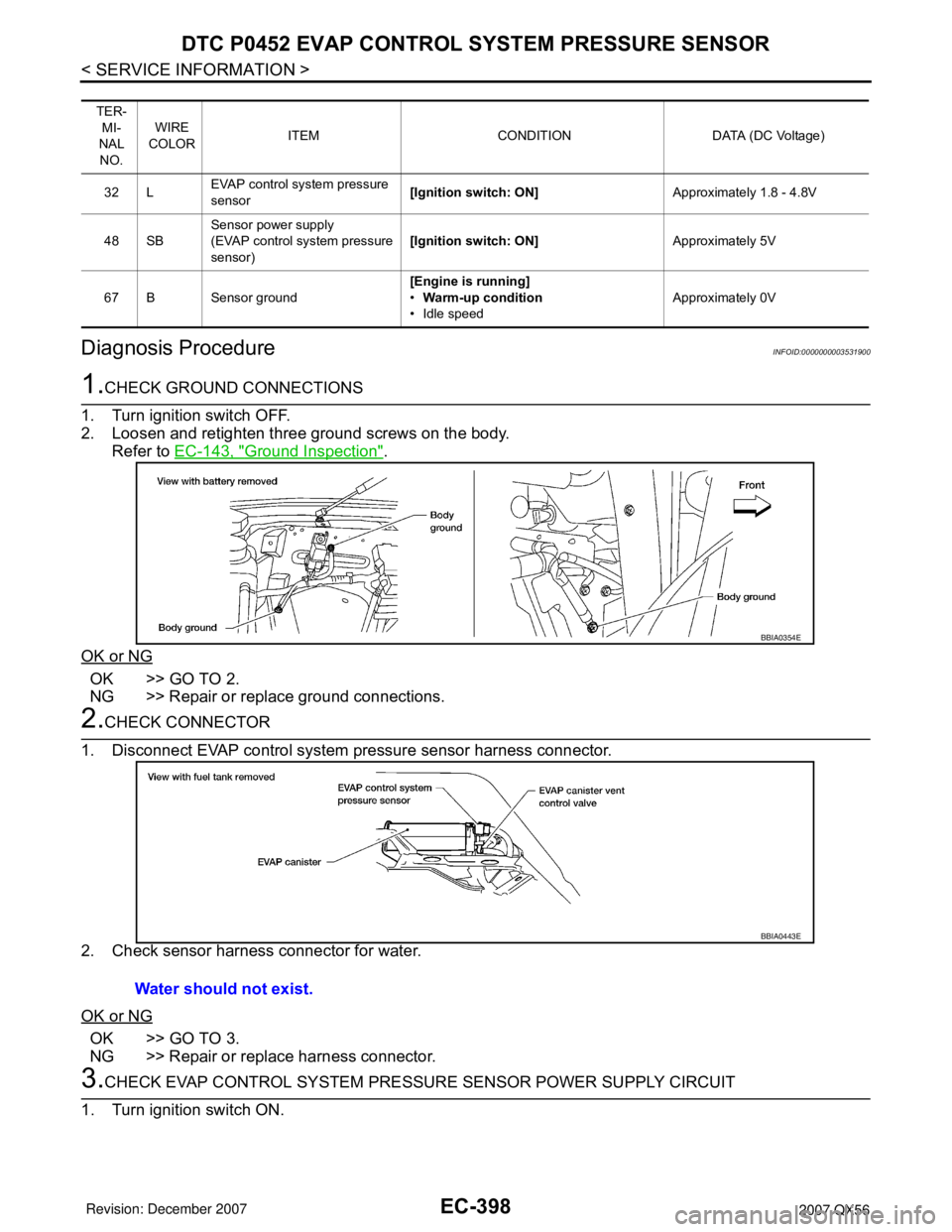
1. Disconnect EVAP control system pressure sensor harness connector.
2. Check sensor harness connector for water.
OK or NG
OK >> GO TO 3.
NG >> Repair or replace harness connector.
3.CHECK EVAP CONTROL SYSTEM PRESSURE SENSOR POWER SUPPLY CIRCUIT
1. Turn ignition switch ON.
TER-
MI-
NAL
NO.WIRE
COLORITEM CONDITION DATA (DC Voltage)
32 LEVAP control system pressure
sensor[Ignition switch: ON]Approximately 1.8 - 4.8V
48 SBSensor power supply
(EVAP control system pressure
sensor)[Ignition switch: ON]Approximately 5V
67 B Sensor ground[Engine is running]
•Warm-up condition
• Idle speedApproximately 0V
BBIA0354E
Water should not exist.
BBIA0443E
Page 1485 of 3061
EC-402
< SERVICE INFORMATION >
DTC P0453 EVAP CONTROL SYSTEM PRESSURE SENSOR
1. Start engine and warm it up to normal operating temperature.
2. Turn ignition switch OFF and wait at least 10 seconds.
3. Turn ignition switch ON.
4. Select “DATA MONITOR” mode with CONSULT-II.
5. Make sure that “FUEL T/TMP SE” is more than 0°C (32°F).
6. Start engine and wait at least 20 seconds.
7. If 1st trip DTC is detected, go to EC-404, "
Diagnosis Procedure".
WITH GST
1. Start engine and warm it up to normal operating temperature.
2. Check that voltage between ECM terminal 107 (Fuel tank tem-
perature sensor signal) and ground is less than 4.2V.
3. Turn ignition switch OFF and wait at least 10 seconds.
4. Start engine and wait at least 20 seconds.
5. Select Service $07 with GST.
If 1st trip DTC is detected, go to EC-404, "
Diagnosis Procedure".
SEF194Y
PBIB1110E
Page 1487 of 3061
EC-404
< SERVICE INFORMATION >
DTC P0453 EVAP CONTROL SYSTEM PRESSURE SENSOR
Diagnosis Procedure
INFOID:0000000003531907
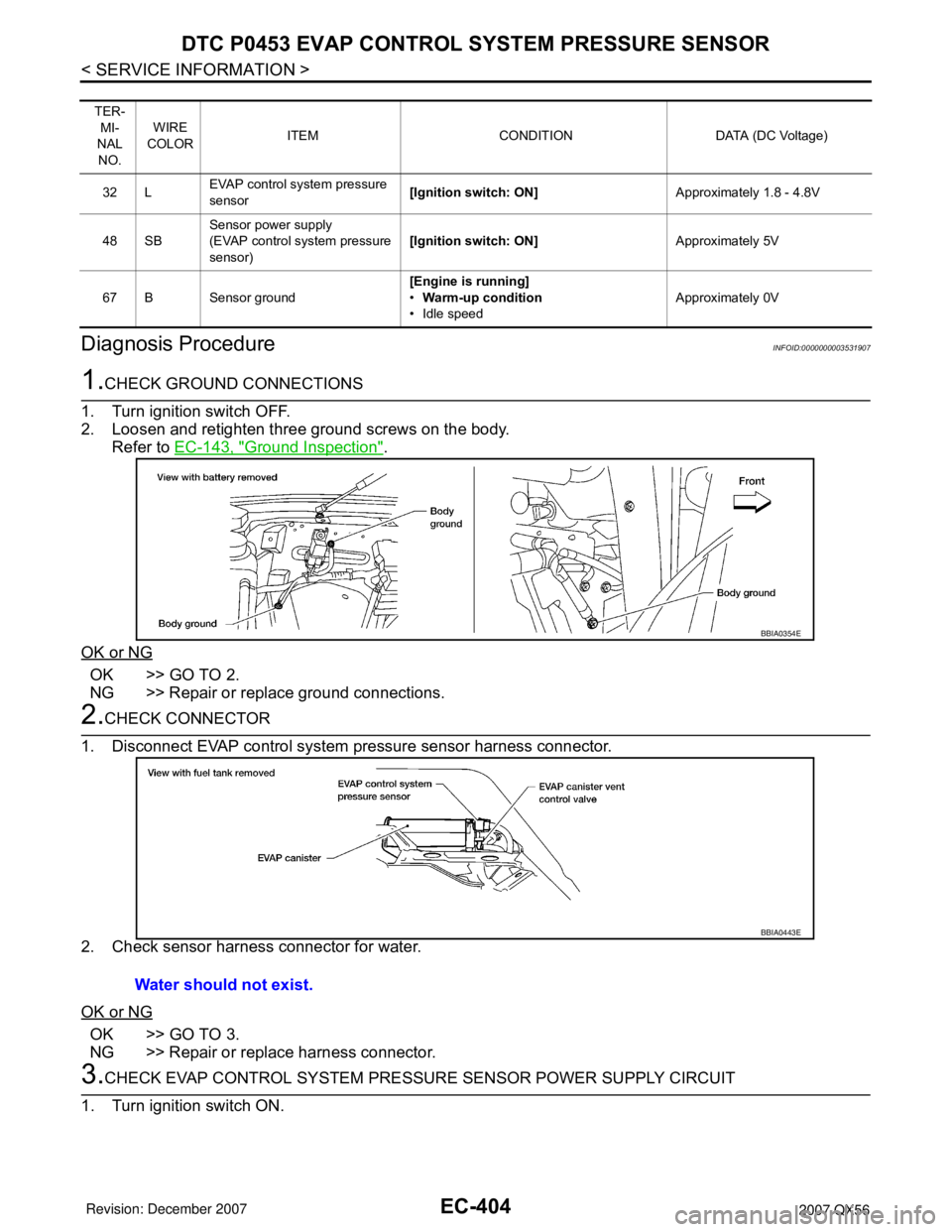
1.CHECK GROUND CONNECTIONS
1. Turn ignition switch OFF.
2. Loosen and retighten three ground screws on the body.
Refer to EC-143, "
Ground Inspection".
OK or NG
OK >> GO TO 2.
NG >> Repair or replace ground connections.
2.CHECK CONNECTOR
1. Disconnect EVAP control system pressure sensor harness connector.
2. Check sensor harness connector for water.
OK or NG
OK >> GO TO 3.
NG >> Repair or replace harness connector.
3.CHECK EVAP CONTROL SYSTEM PRESSURE SENSOR POWER SUPPLY CIRCUIT
1. Turn ignition switch ON.
TER-
MI-
NAL
NO.WIRE
COLORITEM CONDITION DATA (DC Voltage)
32 LEVAP control system pressure
sensor[Ignition switch: ON]Approximately 1.8 - 4.8V
48 SBSensor power supply
(EVAP control system pressure
sensor)[Ignition switch: ON]Approximately 5V
67 B Sensor ground[Engine is running]
•Warm-up condition
• Idle speedApproximately 0V
BBIA0354E
Water should not exist.
BBIA0443E
Page 1495 of 3061
EC-412
< SERVICE INFORMATION >
DTC P0455 EVAP CONTROL SYSTEM
1. Turn ignition switch OFF.
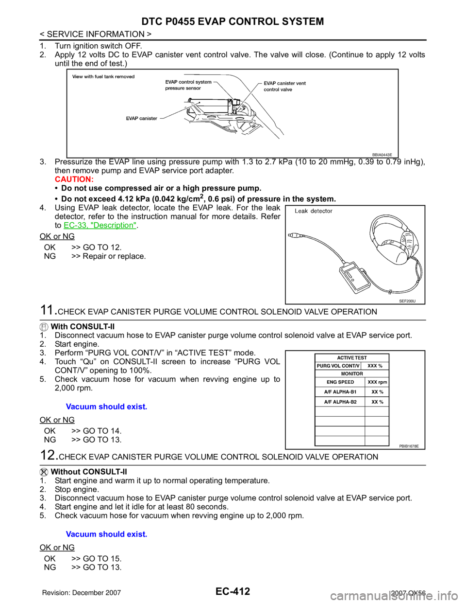
2. Apply 12 volts DC to EVAP canister vent control valve. The valve will close. (Continue to apply 12 volts
until the end of test.)
3. Pressurize the EVAP line using pressure pump with 1.3 to 2.7 kPa (10 to 20 mmHg, 0.39 to 0.79 inHg),
then remove pump and EVAP service port adapter.
CAUTION:
• Do not use compressed air or a high pressure pump.
• Do not exceed 4.12 kPa (0.042 kg/cm
2, 0.6 psi) of pressure in the system.
4. Using EVAP leak detector, locate the EVAP leak. For the leak
detector, refer to the instruction manual for more details. Refer
to EC-33, "
Description".
OK or NG
OK >> GO TO 12.
NG >> Repair or replace.
11 .CHECK EVAP CANISTER PURGE VOLUME CONTROL SOLENOID VALVE OPERATION
With CONSULT-II
1. Disconnect vacuum hose to EVAP canister purge volume control solenoid valve at EVAP service port.
2. Start engine.
3. Perform “PURG VOL CONT/V” in “ACTIVE TEST” mode.
4. Touch “Qu” on CONSULT-II screen to increase “PURG VOL
CONT/V” opening to 100%.
5. Check vacuum hose for vacuum when revving engine up to
2,000 rpm.
OK or NG
OK >> GO TO 14.
NG >> GO TO 13.
12.CHECK EVAP CANISTER PURGE VOLUME CONTROL SOLENOID VALVE OPERATION
Without CONSULT-II
1. Start engine and warm it up to normal operating temperature.
2. Stop engine.
3. Disconnect vacuum hose to EVAP canister purge volume control solenoid valve at EVAP service port.
4. Start engine and let it idle for at least 80 seconds.
5. Check vacuum hose for vacuum when revving engine up to 2,000 rpm.
OK or NG
OK >> GO TO 15.
NG >> GO TO 13.
BBIA0443E
SEF200U
Vacuum should exist.
PBIB1678E
Vacuum should exist.