2007 INFINITI QX56 diagram
[x] Cancel search: diagramPage 2533 of 3061
RF-1
BODY
C
D
E
F
G
H
J
K
L
M
SECTION RF
A
B
RF
N
O
P
CONTENTS
ROOF
SERVICE INFORMATION ............................2
PRECAUTIONS ...................................................2
Precaution for Supplemental Restraint System
(SRS) "AIR BAG" and "SEAT BELT PRE-TEN-
SIONER" ...................................................................
2
Precaution .................................................................2
PREPARATION ...................................................3
Special Service Tool .................................................3
Commercial Service Tool ..........................................3
SQUEAK AND RATTLE TROUBLE DIAGNO-
SIS .......................................................................
4
Work Flow .................................................................4
Generic Squeak and Rattle Troubleshooting ............6
Diagnostic Worksheet ...............................................8
SUNROOF ..........................................................10
Component Parts and Harness Connector Loca-
tion ..........................................................................
10
System Description .................................................10
CAN Communication System Description ...............11
Wiring Diagram - SROOF - ......................................12
Terminal and Reference Value for BCM ..................13
Sunroof Motor Assembly Harness Connector Ter-
minal Layout ............................................................
14
Terminal and Reference Value for Sunroof Motor
Assembly .................................................................
14
Work Flow ................................................................14
CONSULT-II Function (BCM) ..................................14
Work Support ...........................................................15
Active Test ...............................................................15
Data Monitor ............................................................15
Trouble Diagnosis Chart by Symptom .....................15
BCM Power Supply and Ground Circuit Inspection
....
16
Sunroof Switch System Inspection ..........................16
Sunroof Motor Assembly Power Supply and
Ground Circuit Inspection ........................................
16
Door Switch Check ..................................................18
Fitting Adjustment ....................................................20
Removal and Installation .........................................20
Page 2544 of 3061
RF-12
< SERVICE INFORMATION >
SUNROOF
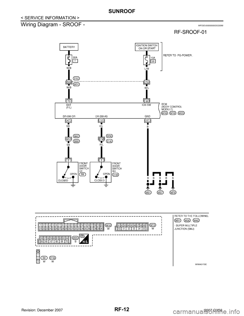
Wiring Diagram - SROOF -
INFOID:0000000003533098
WIWA0170E
Page 2591 of 3061
RSU-1
SUSPENSION
C
D
F
G
H
I
J
K
L
M
SECTION RSU
A
B
RSU
N
O
PCONTENTS
REAR SUSPENSION
SERVICE INFORMATION ............................2
PRECAUTIONS ...................................................2
Precaution for Supplemental Restraint System
(SRS) "AIR BAG" and "SEAT BELT PRE-TEN-
SIONER" ...................................................................
2
Precaution for Rear Suspension ...............................2
PREPARATION ...................................................3
Commercial Service Tool ..........................................3
NOISE, VIBRATION AND HARSHNESS
(NVH) TROUBLESHOOTING .............................
4
NVH Troubleshooting Chart ......................................4
CAN COMMUNICATION .....................................5
System Description ...................................................5
TROUBLE DIAGNOSIS ......................................6
How to Perform Trouble Diagnosis for Quick and
Accurate Repair ........................................................
6
Component Parts and Harness Connector Loca-
tion ............................................................................
8
Wiring Diagram - A/SUSP - .......................................9
Basic Inspection ......................................................10
Chek Suspension Indicator Lamp Timing ...............11
Control Unit Input/Output Signal Standard ..............11
CONSULT-II Function (AIR LEVELIZER) ...............11
TROUBLE DIAGNOSIS FOR SELF-DIAG-
NOSTIC ITEMS ..................................................
14
Height Sensor System Inspection ...........................14
Exhaust Valve Solenoid System Inspection ............15
Compressor Motor, Compressor Motor Relay and
Circuit Inspection .....................................................
17
TROUBLE DIAGNOSES FOR SYMPTOMS ......19
Load Leveling Rear Air Suspension System Does
Not Operate .............................................................
19
Chek Suspension Indicator Lamp Stays On When
Ignition Switch Is Turned On ...................................
20
REAR SUSPENSION ASSEMBLY ...................21
Component ..............................................................21
On-Vehicle Inspection and Service .........................22
Wheel AlignmentInspection .....................................23
REAR SUSPENSION MEMBER .......................26
Removal and Installation .........................................26
SHOCK ABSORBER ........................................30
Removal and Installation .........................................30
SUSPENSION ARM ..........................................31
Removal and Installation .........................................31
FRONT LOWER LINK .......................................33
Removal and Installation .........................................33
REAR LOWER LINK & COIL SPRING .............35
Removal and Installation .........................................35
STABILIZER BAR .............................................37
Removal and Installation .........................................37
REAR LOAD LEVELING AIR SUSPENSION
COMPRESSOR ASSEMBLY ............................
38
Removal and Installation .........................................38
HEIGHT SENSOR .............................................40
Removal and Installation .........................................40
CONTROL UNIT ................................................42
Removal and Installation .........................................42
Initialization Procedure ............................................42
SERVICE DATA AND SPECIFICATIONS
(SDS) .................................................................
43
Wheel Alignment .....................................................43
Ball Joint ..................................................................43
Wheelarch Height (Unladen*1) ................................44
Page 2599 of 3061
TROUBLE DIAGNOSIS
RSU-9
< SERVICE INFORMATION >
C
D
F
G
H
I
J
K
L
MA
B
RSU
N
O
P
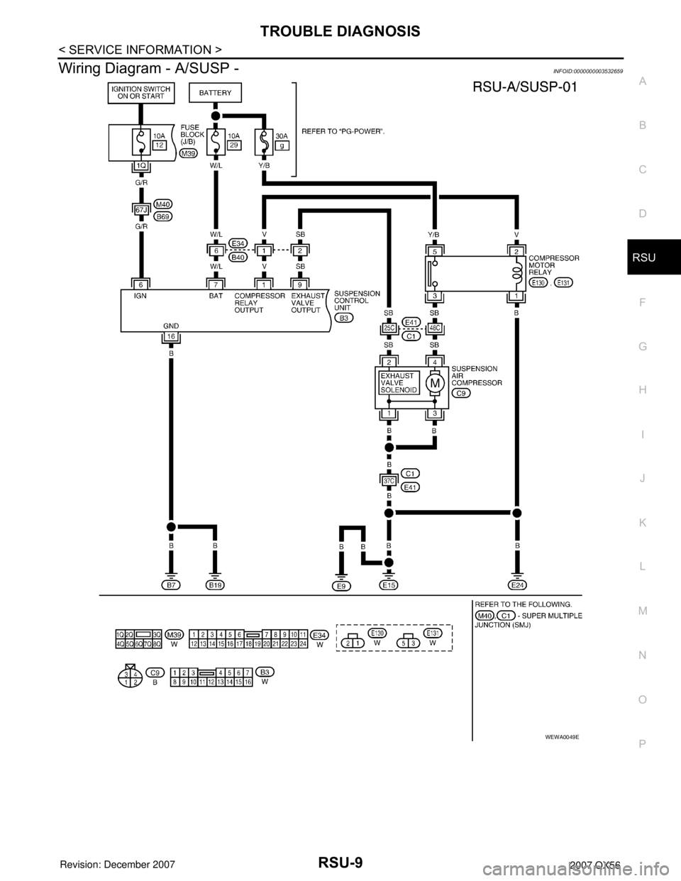
Wiring Diagram - A/SUSP -INFOID:0000000003532659
WEWA0049E
Page 2649 of 3061
SC-1
ELECTRICAL
C
D
E
F
G
H
I
J
L
M
SECTION SC
A
B
SC
N
O
P
CONTENTS
STARTING & CHARGING SYSTEM
SERVICE INFORMATION ............................2
PRECAUTIONS ...................................................2
Precaution for Supplemental Restraint System
(SRS) "AIR BAG" and "SEAT BELT PRE-TEN-
SIONER" ...................................................................
2
Precaution for Power Generation Variable Voltage
Control System ..........................................................
2
PREPARATION ...................................................3
Special Service Tool .................................................3
Commercial Service Tool ..........................................3
BATTERY ............................................................4
How to Handle Battery ..............................................4
Trouble Diagnosis with Battery/Starting/Charging
System Tester ...........................................................
6
Removal and Installation ...........................................8
STARTING SYSTEM ..........................................9
System Description ...................................................9
Wiring Diagram - START - .......................................10
Trouble Diagnosis with Battery/Starting/Charging
System Tester .........................................................
10
Removal and Installation .........................................14
CHARGING SYSTEM .......................................15
System Description ..................................................15
Wiring Diagram - CHARGE - ...................................17
Trouble Diagnosis with Battery/Starting/Charging
System Tester .........................................................
17
Removal and Installation .........................................22
SERVICE DATA AND SPECIFICATIONS
(SDS) .................................................................
24
Battery .....................................................................24
Starter ......................................................................24
Generator ................................................................24
Page 2658 of 3061
SC-10
< SERVICE INFORMATION >
STARTING SYSTEM
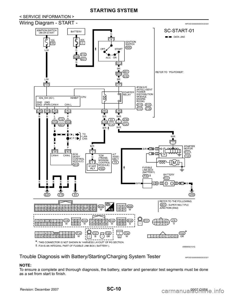
Wiring Diagram - START -
INFOID:0000000003533320
Trouble Diagnosis with Battery/Starting/Charging System TesterINFOID:0000000003533321
NOTE:
To ensure a complete and thorough diagnosis, the battery, starter and generator test segments must be done
as a set from start to finish.
AWBWA0151G
Page 2665 of 3061
CHARGING SYSTEM
SC-17
< SERVICE INFORMATION >
C
D
E
F
G
H
I
J
L
MA
B
SC
N
O
P
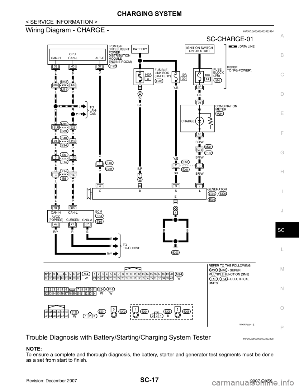
Wiring Diagram - CHARGE -INFOID:0000000003533324
Trouble Diagnosis with Battery/Starting/Charging System TesterINFOID:0000000003533325
NOTE:
To ensure a complete and thorough diagnosis, the battery, starter and generator test segments must be done
as a set from start to finish.
WKWA5141E
Page 2673 of 3061
SE-1
BODY
C
D
E
F
G
H
J
K
L
M
SECTION SE
A
B
SE
N
O
P
CONTENTS
SEAT
SERVICE INFORMATION ............................3
PRECAUTIONS ...................................................3
Precaution for Supplemental Restraint System
(SRS) "AIR BAG" and "SEAT BELT PRE-TEN-
SIONER" ...................................................................
3
Precaution for Work ..................................................3
PREPARATION ...................................................4
Special Service Tool .................................................4
Commercial Service Tool ..........................................4
SQUEAK AND RATTLE TROUBLE DIAGNO-
SIS .......................................................................
5
Work Flow .................................................................5
Generic Squeak and Rattle Troubleshooting ............7
Diagnostic Worksheet ...............................................9
AUTOMATIC DRIVE POSITIONER ...................11
Component Parts and Harness Connector Loca-
tion ..........................................................................
11
System Description .................................................11
CAN Communication System Description ...............13
Schematic ...............................................................13
Wiring Diagram - AUT/DP - .....................................15
Terminal and Reference Value for BCM .................24
Driver Seat Control Unit Harness Connector Ter-
minal Layout ............................................................
25
Terminal and Reference Value for Driver Seat
Control Unit .............................................................
25
Automatic Drive Positioner Control Unit Harness
Connector Terminal Layout .....................................
28
Terminal and Reference Value for Automatic
Drive Positioner Control Unit ...................................
28
Work Flow ...............................................................30
Preliminary Check ...................................................30
BCM Power Supply and Ground Circuit Inspection
....
31
Power Supply and Ground Circuit Inspection .........31
CONSULT-II Function (AUTO DRIVE POS.) ..........32
CAN Communication Inspection Using CON-
SULT-II (Self-Diagnosis) ..........................................
35
Symptom Chart ........................................................35
Sliding Motor Circuit Inspection ...............................37
Reclining Motor LH Circuit Inspection .....................38
Lifting Motor (Front) Circuit Inspection ....................39
Lifting Motor (Rear) Circuit Inspection .....................40
Pedal Adjusting Motor Circuit Inspection .................41
Mirror Motor LH Circuit Inspection ...........................42
Mirror Motor RH Circuit Inspection ..........................44
Steering Wheel Tilt Circuit Inspection ......................45
Sliding Sensor Circuit Inspection .............................46
Reclining Sensor Circuit Inspection .........................47
Lifting Sensor (Front) Circuit Inspection ..................48
Lifting Sensor (Rear) Circuit Inspection ...................49
Pedal Adjusting Sensor Circuit Inspection ...............50
Mirror Sensor LH Circuit Inspection .........................51
Mirror Sensor RH Circuit Inspection ........................53
Steering Wheel Tilt Sensor Circuit Inspection .........54
Sliding Switch Circuit Inspection ..............................55
Reclining Switch Inspection .....................................56
Lifting Switch (Front) Circuit Inspection ...................58
Lifting Switch (Rear) Circuit Inspection ....................59
Power Seat Switch Ground Inspection ....................60
Pedal Adjusting Switch Circuit Inspection ...............61
Door Mirror Remote Control Switch (Changeover
Switch) Circuit Inspection ........................................
62
Door Mirror Remote Control Switch (Mirror
Switch) Circuit Inspection ........................................
64
Door Mirror Remote Control Switch Ground Circuit
Inspection ................................................................
65
Seat Memory Switch Circuit Inspection ...................66
Seat Memory Indicator Lamp Circuit Inspection ......67
Door Mirror Sensor Power Supply and Ground
Circuit inspection .....................................................
69
A/T Device (Park Position Switch) Circuit Inspec-
tion ...........................................................................
69
Steering Wheel Tilt Switch Circuit Inspection ..........70
Front Door Switch LH Circuit Inspection ..................72
UART Communication Line Circuit Inspection ........73