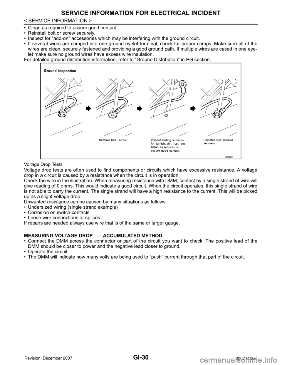
2007 INFINITI QX56 wiring
[x] Cancel search: wiringPage 1994 of 3061

GI-28
< SERVICE INFORMATION >
SERVICE INFORMATION FOR ELECTRICAL INCIDENT
ough understanding of system operation. Then you will be able to use the appropriate equipment and follow
the correct test procedure.
You may have to simulate vehicle vibrations while testing electrical components. Gently shake the wiring har-
ness or electrical component to do this.
NOTE:
Refer to “How to Check Terminal” to probe or check terminal.
Testing for “Opens” in the Circuit
Before you begin to diagnose and test the system, you should rough sketch a schematic of the system. This
will help you to logically walk through the diagnosis process. Drawing the sketch will also reinforce your work-
ing knowledge of the system.
CONTINUITY CHECK METHOD
The continuity check is used to find an open in the circuit. The digital multimeter (DMM) set on the resistance
function will indicate an open circuit as over limit (no beep tone or no ohms symbol). Make sure to always start
with the DMM at the highest resistance level.
To help in understanding the diagnosis of open circuits, please refer to the previous schematic.
• Disconnect the battery negative cable.
• Start at one end of the circuit and work your way to the other end. (At the fuse block in this example)
• Connect one probe of the DMM to the fuse block terminal on the load side.
• Connect the other probe to the fuse block (power) side of SW1. Little or no resistance will indicate that por-
tion of the circuit has good continuity. If there were an open in the circuit, the DMM would indicate an over
limit or infinite resistance condition. (point A)
• Connect the probes between SW1 and the relay. Little or no resistance will indicate that portion of the circuit
has good continuity. If there were an open in the circuit, the DMM would indicate an over limit or infinite resis-
tance condition. (point B)
• Connect the probes between the relay and the solenoid. Little or no resistance will indicate that portion of the
circuit has good continuity. If there were an open in the circuit, the DMM would indicate an over limit or infi-
nite resistance condition. (point C)
Any circuit can be diagnosed using the approach in the previous example.
VOLTAGE CHECK METHOD
To help in understanding the diagnosis of open circuits please refer to the previous schematic.
In any powered circuit, an open can be found by methodically checking the system for the presence of voltage.
This is done by switching the DMM to the voltage function.
• Connect one probe of the DMM to a known good ground.
• Begin probing at one end of the circuit and work your way to the other end.
• With SW1 open, probe at SW1 to check for voltage.
voltage; open is further down the circuit than SW1.
no voltage; open is between fuse block and SW1 (point A).
• Close SW1 and probe at relay.
voltage; open is further down the circuit than the relay.
no voltage; open is between SW1 and relay (point B).
OPEN A circuit is open when there is no continuity through a section of the circuit.
SHORTThere are two types of shorts.
• SHORT CIRCUITWhen a circuit contacts another circuit and causes the normal resistance to
change.
• SHORT TO GROUND When a circuit contacts a ground source and grounds the circuit.
SGI846-A
Page 1996 of 3061

GI-30
< SERVICE INFORMATION >
SERVICE INFORMATION FOR ELECTRICAL INCIDENT
• Clean as required to assure good contact.
• Reinstall bolt or screw securely.
• Inspect for “add-on” accessories which may be interfering with the ground circuit.
• If several wires are crimped into one ground eyelet terminal, check for proper crimps. Make sure all of the
wires are clean, securely fastened and providing a good ground path. If multiple wires are cased in one eye-
let make sure no ground wires have excess wire insulation.
For detailed ground distribution information, refer to “Ground Distribution” in PG section.
Voltage Drop Tests
Voltage drop tests are often used to find components or circuits which have excessive resistance. A voltage
drop in a circuit is caused by a resistance when the circuit is in operation.
Check the wire in the illustration. When measuring resistance with DMM, contact by a single strand of wire will
give reading of 0 ohms. This would indicate a good circuit. When the circuit operates, this single strand of wire
is not able to carry the current. The single strand will have a high resistance to the current. This will be picked
up as a slight voltage drop.
Unwanted resistance can be caused by many situations as follows:
• Undersized wiring (single strand example)
• Corrosion on switch contacts
• Loose wire connections or splices.
If repairs are needed always use wire that is of the same or larger gauge.
MEASURING VOLTAGE DROP — ACCUMULATED METHOD
• Connect the DMM across the connector or part of the circuit you want to check. The positive lead of the
DMM should be closer to power and the negative lead closer to ground.
• Operate the circuit.
• The DMM will indicate how many volts are being used to “push” current through that part of the circuit.
SGI853
Page 2005 of 3061

CONSULT-II CHECKING SYSTEM
GI-39
< SERVICE INFORMATION >
C
D
E
F
G
H
I
J
K
L
MB
GI
N
O
P
NOTE:
The preceding schematic is an example and may not be a true representation of the vehicle. The actual DDL1
circuits (CAN lines) from DLC pins 6 and 14 as well as the DDL2 circuit (K-line) from DLC pin 7 may be con-
nected to more than one system. A short in a DDL circuit connected to a control unit in one system may affect
CONSULT-II access to other systems.
Symptom Check item
CONSULT-II cannot access
any system.• CONSULT-II DLC power supply circuit (Terminal 8) and ground circuit (Terminal 4). For detailed cir-
cuit, refer to EC-643, "
Wiring Diagram".
• CONSULT-II DLC cable and CONSULT-II CONVERTER.
CONSULT-II cannot access in-
dividual system. (Other sys-
tems can be accessed.)• CONSULT-II program card (Check the appropriate CONSULT-II program card for the system. Refer
to GI-36, "
Checking Equipment".
• Power supply and ground circuit for the control unit of the system (For detailed circuit, refer to wiring
diagram for each system).
• Open or short circuit between the system and CONSULT-II DLC (For detailed circuit, refer to wiring
diagram for each system).
• Open or short circuit in CAN or K communication line. Refer to LAN-7
.
Page 2020 of 3061

GW-1
BODY
C
D
E
F
G
H
J
K
L
M
SECTION GW
A
B
GW
N
O
P
CONTENTS
GLASSES, WINDOW SYSTEM & MIRRORS
SERVICE INFORMATION ............................3
PRECAUTIONS ...................................................3
Precaution for Supplemental Restraint System
(SRS) "AIR BAG" and "SEAT BELT PRE-TEN-
SIONER" ...................................................................
3
Handling for Adhesive and Primer ............................3
PREPARATION ...................................................4
Special Service Tool .................................................4
Commercial Service Tool ..........................................4
SQUEAK AND RATTLE TROUBLE DIAGNO-
SIS .......................................................................
5
Work Flow .................................................................5
Generic Squeak and Rattle Troubleshooting ............7
Diagnostic Worksheet ...............................................9
WINDSHIELD GLASS ........................................11
Removal and Installation .........................................11
REAR WINDOW GLASS AND MOLDING .........13
Removal and Installation .........................................13
POWER WINDOW SYSTEM ..............................15
Component Parts and Harness Connector Loca-
tion ..........................................................................
15
System Description .................................................15
CAN Communication System Description ...............18
Schematic ...............................................................19
Wiring Diagram - WINDOW- ...................................21
Main Power Window and Door Lock/Unlock
Switch Harness Connector Terminal Layout ...........
28
Terminal and Reference Value for Main Power
Window and Door Lock/Unlock Switch ...................
29
Power Window and Door Lock/Unlock Switch RH
Harness Connector Terminal Layout ......................
30
Terminal and Reference Value for Power Window
and Door Lock/Unlock Switch RH ...........................
30
Terminal and Reference Value for BCM .................31
Work Flow ...............................................................31
CONSULT-II Function (BCM) ..................................31
Trouble Diagnosis Symptom Chart ..........................32
BCM Power Supply and Ground Circuit Inspection
....
34
Main Power Window and Door Lock/Unlock
Switch Power Supply and Ground Circuit Inspec-
tion ...........................................................................
34
Power Window and Door Lock/Unlock Switch RH
Power Supply and Ground Circuit Inspection ..........
35
Front Power Window Motor LH Circuit Inspection ....36
Front Power Window Motor RH Circuit Inspection ....37
Limit Switch Circuit Inspection Front LH ..................37
Limit Switch Circuit Inspection Front RH .................38
Encoder Circuit Inspection Front LH ........................40
Encoder Circuit Inspection Front RH .......................41
Door Switch Check ..................................................43
Front Door Lock Assembly LH (Key Cylinder
Switch) Check ..........................................................
44
Power Window Serial Link Check Front LH and
RH ...........................................................................
46
Rear Power Window Control Unit LH or RH Power
Supply and Ground Circuit Inspection .....................
48
Rear Power Window Switch LH or RH Power Sup-
ply and Ground Circuit Inspection ...........................
49
Rear Power Window Motor LH Circuit Inspection ....50
Rear Power Window Motor RH Circuit Inspection ....50
Limit Switch Circuit Inspection Rear LH and RH .....51
Encoder Circuit Inspection Rear LH or RH ..............53
Power Window Serial Link Check Rear LH or RH ....54
Rear Power Vent Window Switch Circuit Inspec-
tion ...........................................................................
55
Rear Power Vent Window Motor LH Circuit In-
spection ...................................................................
55
Rear Power Vent Window Motor RH Circuit In-
spection ...................................................................
56
Rear Power Vent Window Relay (OPEN) Check ....56
Rear Power Vent Window Relay (CLOSE) Check ....57
FRONT DOOR GLASS AND REGULATOR .....59
Removal and Installation .........................................59
REAR DOOR GLASS AND REGULATOR .......62
Page 2021 of 3061

GW-2
Removal and Installation ........................................62
SIDE WINDOW GLASS .....................................65
Removal and Installation ........................................65
INSIDE MIRROR ................................................66
Wiring Diagram - I/MIRR - ......................................66
Removal and Installation ........................................66
REAR WINDOW DEFOGGER ...........................68
Component Parts and Harness Connector Loca-
tion ..........................................................................
68
System Description .................................................68
CAN Communication System Description ..............69
Schematic ...............................................................70
Wiring Diagram - DEF - ..........................................71
Terminal and Reference Value for BCM .................73
Terminal and Reference Value for IPDM E/R .........73
Work Flow ...............................................................74
CONSULT-II Function (BCM) .................................74
Trouble Diagnosis Symptom Chart .........................74
BCM Power Supply and Ground Circuit Inspection
...
75
Rear Window Defogger Switch Circuit Inspection ...75
Rear Window Defogger Circuit Inspection ..............76
Door Mirror Defogger Power Supply Circuit In-
spection ...................................................................
77
Door Mirror LH (Door Mirror Defogger) Circuit In-
spection ...................................................................
78
Door Mirror RH (Door Mirror Defogger) Circuit In-
spection ...................................................................
79
Rear Window Defogger Signal Inspection ..............80
Filament Check .......................................................80
Filament Repair .......................................................81
DOOR MIRROR .................................................83
Wiring Diagram - MIRROR - ...................................83
Door Mirror Assembly .............................................84
Door Mirror Glass ....................................................84
Page 2022 of 3061

PRECAUTIONS
GW-3
< SERVICE INFORMATION >
C
D
E
F
G
H
J
K
L
MA
B
GW
N
O
P
SERVICE INFORMATION
PRECAUTIONS
Precaution for Supplemental Restraint System (SRS) "AIR BAG" and "SEAT BELT
PRE-TENSIONER"
INFOID:0000000003533015
The Supplemental Restraint System such as “AIR BAG” and “SEAT BELT PRE-TENSIONER”, used along
with a front seat belt, helps to reduce the risk or severity of injury to the driver and front passenger for certain
types of collision. This system includes seat belt switch inputs and dual stage front air bag modules. The SRS
system uses the seat belt switches to determine the front air bag deployment, and may only deploy one front
air bag, depending on the severity of a collision and whether the front occupants are belted or unbelted.
Information necessary to service the system safely is included in the SRS and SB section of this Service Man-
ual.
WARNING:
• To avoid rendering the SRS inoperative, which could increase the risk of personal injury or death in
the event of a collision which would result in air bag inflation, all maintenance must be performed by
an authorized NISSAN/INFINITI dealer.
• Improper maintenance, including incorrect removal and installation of the SRS, can lead to personal
injury caused by unintentional activation of the system. For removal of Spiral Cable and Air Bag
Module, see the SRS section.
• Do not use electrical test equipment on any circuit related to the SRS unless instructed to in this
Service Manual. SRS wiring harnesses can be identified by yellow and/or orange harnesses or har-
ness connectors.
Handling for Adhesive and PrimerINFOID:0000000003533016
• Do not use an adhesive which is past its usable date. Shelf life of this product is limited to six months after
the date of manufacture. Carefully adhere to the expiration or manufacture date printed on the box.
• Keep primers and adhesive in a cool, dry place. Ideally, they should be stored in a refrigerator.
• Open the seal of the primer and adhesive just before application. Discard the remainder.
• Before application, be sure to shake the primer container to stir the contents. If any floating material is found,
do not use it.
• If any primer or adhesive contacts the skin, wipe it off with gasoline or equivalent and wash the skin with
soap.
• When using primer and adhesive, always observe the precautions in the instruction manual.
Page 2026 of 3061

SQUEAK AND RATTLE TROUBLE DIAGNOSIS
GW-7
< SERVICE INFORMATION >
C
D
E
F
G
H
J
K
L
MA
B
GW
N
O
P
SILICONE GREASE
Used instead of UHMW tape that will be visible or not fit.
Note: Will only last a few months.
SILICONE SPRAY
Use when grease cannot be applied.
DUCT TAPE
Use to eliminate movement.
CONFIRM THE REPAIR
Confirm that the cause of a noise is repaired by test driving the vehicle. Operate the vehicle under the same
conditions as when the noise originally occurred. Refer to the notes on the Diagnostic Worksheet.
Generic Squeak and Rattle TroubleshootingINFOID:0000000003533020
Refer to Table of Contents for specific component removal and installation information.
INSTRUMENT PANEL
Most incidents are caused by contact and movement between:
1. The cluster lid A and instrument panel
2. Acrylic lens and combination meter housing
3. Instrument panel to front pillar garnish
4. Instrument panel to windshield
5. Instrument panel mounting pins
6. Wiring harnesses behind the combination meter
7. A/C defroster duct and duct joint
These incidents can usually be located by tapping or moving the components to duplicate the noise or by
pressing on the components while driving to stop the noise. Most of these incidents can be repaired by apply-
ing felt cloth tape or silicone spray (in hard to reach areas). Urethane pads can be used to insulate wiring har-
ness.
CAUTION:
Do not use silicone spray to isolate a squeak or rattle. If you saturate the area with silicone, you will
not be able to recheck the repair.
CENTER CONSOLE
Components to pay attention to include:
1. Shifter assembly cover to finisher
2. A/C control unit and cluster lid C
3. Wiring harnesses behind audio and A/C control unit
The instrument panel repair and isolation procedures also apply to the center console.
DOORS
Pay attention to the:
1. Finisher and inner panel making a slapping noise
2. Inside handle escutcheon to door finisher
3. Wiring harnesses tapping
4. Door striker out of alignment causing a popping noise on starts and stops
Tapping or moving the components or pressing on them while driving to duplicate the conditions can isolate
many of these incidents. You can usually insulate the areas with felt cloth tape or insulator foam blocks from
the NISSAN Squeak and Rattle Kit (J-43980) to repair the noise.
TRUNK
Trunk noises are often caused by a loose jack or loose items put into the trunk by the owner.
In addition look for:
1. Trunk lid bumpers out of adjustment
2. Trunk lid striker out of adjustment
3. The trunk lid torsion bars knocking together
4. A loose license plate or bracket
Page 2040 of 3061

POWER WINDOW SYSTEM
GW-21
< SERVICE INFORMATION >
C
D
E
F
G
H
J
K
L
MA
B
GW
N
O
P
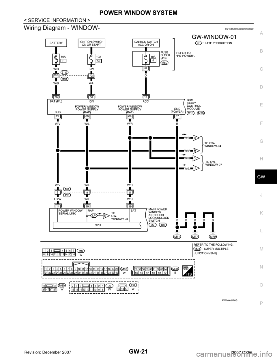
Wiring Diagram - WINDOW-INFOID:0000000003533028
AWKWA0476G