Page 1703 of 3061
EC-620
< SERVICE INFORMATION >
ICC BRAKE SWITCH
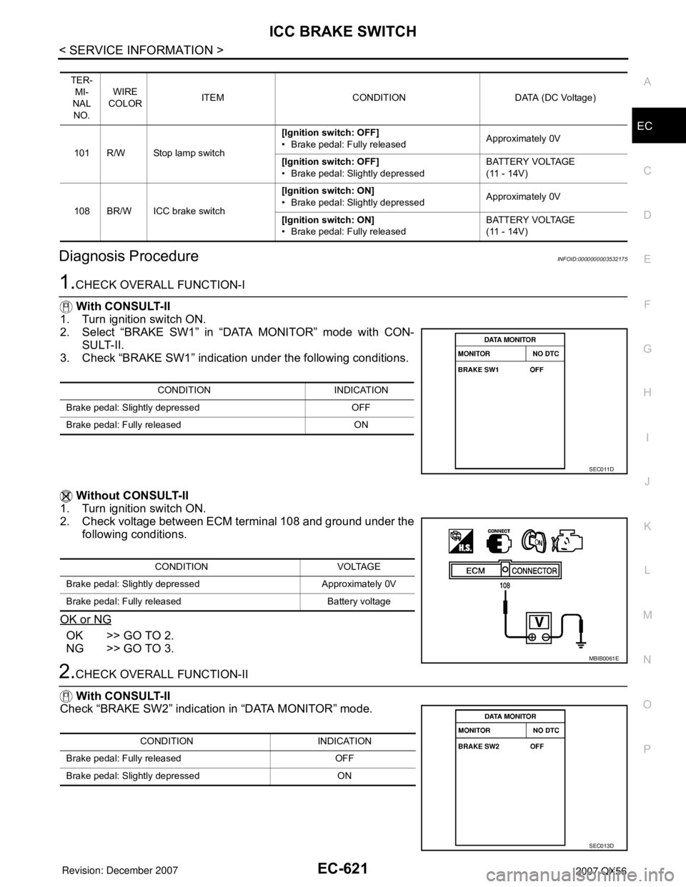
Wiring Diagram
INFOID:0000000003532174
Specification data are reference values and are measured between each terminal and ground.
CAUTION:
Do not use ECM ground terminals when measuring input/output voltage. Doing so may result in dam-
age to the ECM's transistor. Use a ground other than ECM terminals, such as the ground.
BBWA2128E
Page 1704 of 3061
ICC BRAKE SWITCH
EC-621
< SERVICE INFORMATION >
C
D
E
F
G
H
I
J
K
L
MA
EC
N
P O
Diagnosis ProcedureINFOID:0000000003532175
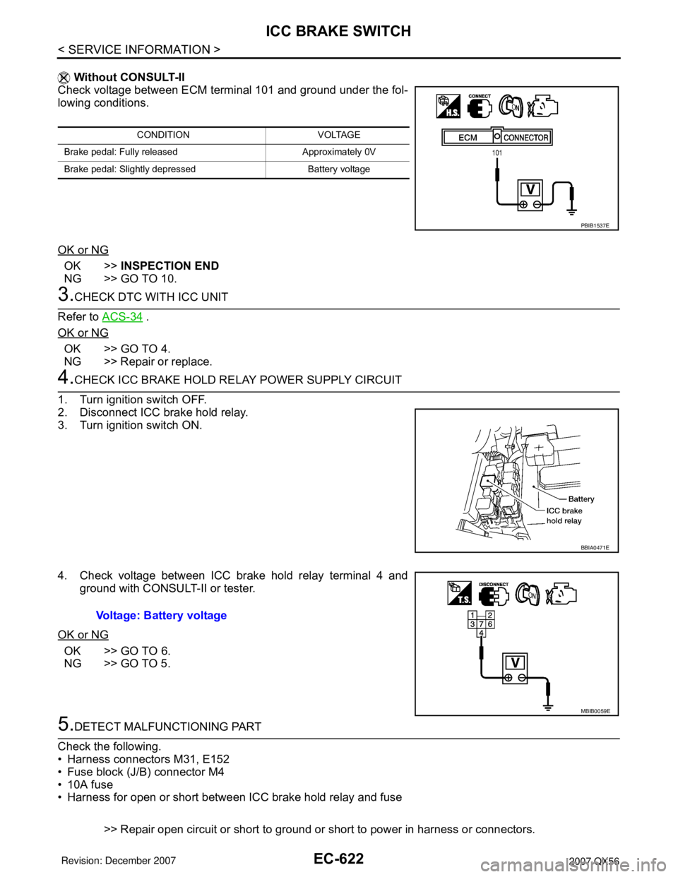
1.CHECK OVERALL FUNCTION-I
With CONSULT-II
1. Turn ignition switch ON.
2. Select “BRAKE SW1” in “DATA MONITOR” mode with CON-
SULT-II.
3. Check “BRAKE SW1” indication under the following conditions.
Without CONSULT-II
1. Turn ignition switch ON.
2. Check voltage between ECM terminal 108 and ground under the
following conditions.
OK or NG
OK >> GO TO 2.
NG >> GO TO 3.
2.CHECK OVERALL FUNCTION-II
With CONSULT-II
Check “BRAKE SW2” indication in “DATA MONITOR” mode.
TER-
MI-
NAL
NO.WIRE
COLORITEM CONDITION DATA (DC Voltage)
101 R/W Stop lamp switch[Ignition switch: OFF]
• Brake pedal: Fully releasedApproximately 0V
[Ignition switch: OFF]
• Brake pedal: Slightly depressedBATTERY VOLTAGE
(11 - 14V)
108 BR/W ICC brake switch[Ignition switch: ON]
• Brake pedal: Slightly depressedApproximately 0V
[Ignition switch: ON]
• Brake pedal: Fully releasedBATTERY VOLTAGE
(11 - 14V)
CONDITION INDICATION
Brake pedal: Slightly depressed OFF
Brake pedal: Fully released ON
SEC011D
CONDITION VOLTAGE
Brake pedal: Slightly depressed Approximately 0V
Brake pedal: Fully released Battery voltage
MBIB0061E
CONDITION INDICATION
Brake pedal: Fully released OFF
Brake pedal: Slightly depressed ON
SEC013D
Page 1705 of 3061
EC-622
< SERVICE INFORMATION >
ICC BRAKE SWITCH
Without CONSULT-II
Check voltage between ECM terminal 101 and ground under the fol-
lowing conditions.
OK or NG
OK >>INSPECTION END
NG >> GO TO 10.
3.CHECK DTC WITH ICC UNIT
Refer to ACS-34
.
OK or NG
OK >> GO TO 4.
NG >> Repair or replace.
4.CHECK ICC BRAKE HOLD RELAY POWER SUPPLY CIRCUIT
1. Turn ignition switch OFF.
2. Disconnect ICC brake hold relay.
3. Turn ignition switch ON.
4. Check voltage between ICC brake hold relay terminal 4 and
ground with CONSULT-II or tester.
OK or NG
OK >> GO TO 6.
NG >> GO TO 5.
5.DETECT MALFUNCTIONING PART
Check the following.
• Harness connectors M31, E152
• Fuse block (J/B) connector M4
• 10A fuse
• Harness for open or short between ICC brake hold relay and fuse
>> Repair open circuit or short to ground or short to power in harness or connectors.
CONDITION VOLTAGE
Brake pedal: Fully released Approximately 0V
Brake pedal: Slightly depressed Battery voltage
PBIB1537E
BBIA0471E
Voltage: Battery voltage
MBIB0059E
Page 1706 of 3061
ICC BRAKE SWITCH
EC-623
< SERVICE INFORMATION >
C
D
E
F
G
H
I
J
K
L
MA
EC
N
P O
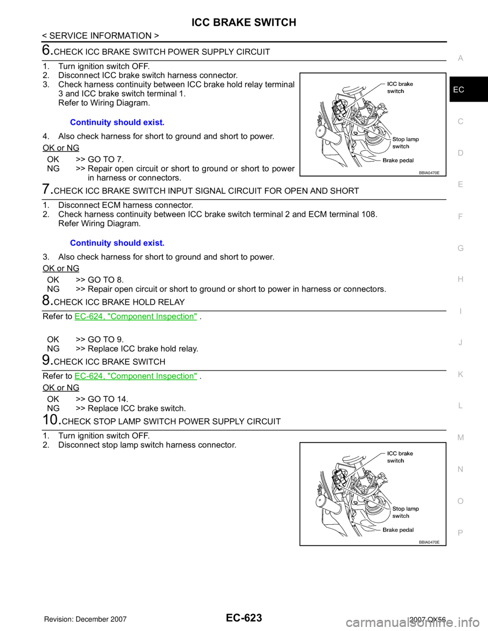
6.CHECK ICC BRAKE SWITCH POWER SUPPLY CIRCUIT
1. Turn ignition switch OFF.
2. Disconnect ICC brake switch harness connector.
3. Check harness continuity between ICC brake hold relay terminal
3 and ICC brake switch terminal 1.
Refer to Wiring Diagram.
4. Also check harness for short to ground and short to power.
OK or NG
OK >> GO TO 7.
NG >> Repair open circuit or short to ground or short to power
in harness or connectors.
7.CHECK ICC BRAKE SWITCH INPUT SIGNAL CIRCUIT FOR OPEN AND SHORT
1. Disconnect ECM harness connector.
2. Check harness continuity between ICC brake switch terminal 2 and ECM terminal 108.
Refer Wiring Diagram.
3. Also check harness for short to ground and short to power.
OK or NG
OK >> GO TO 8.
NG >> Repair open circuit or short to ground or short to power in harness or connectors.
8.CHECK ICC BRAKE HOLD RELAY
Refer to EC-624, "
Component Inspection" .
OK >> GO TO 9.
NG >> Replace ICC brake hold relay.
9.CHECK ICC BRAKE SWITCH
Refer to EC-624, "
Component Inspection" .
OK or NG
OK >> GO TO 14.
NG >> Replace ICC brake switch.
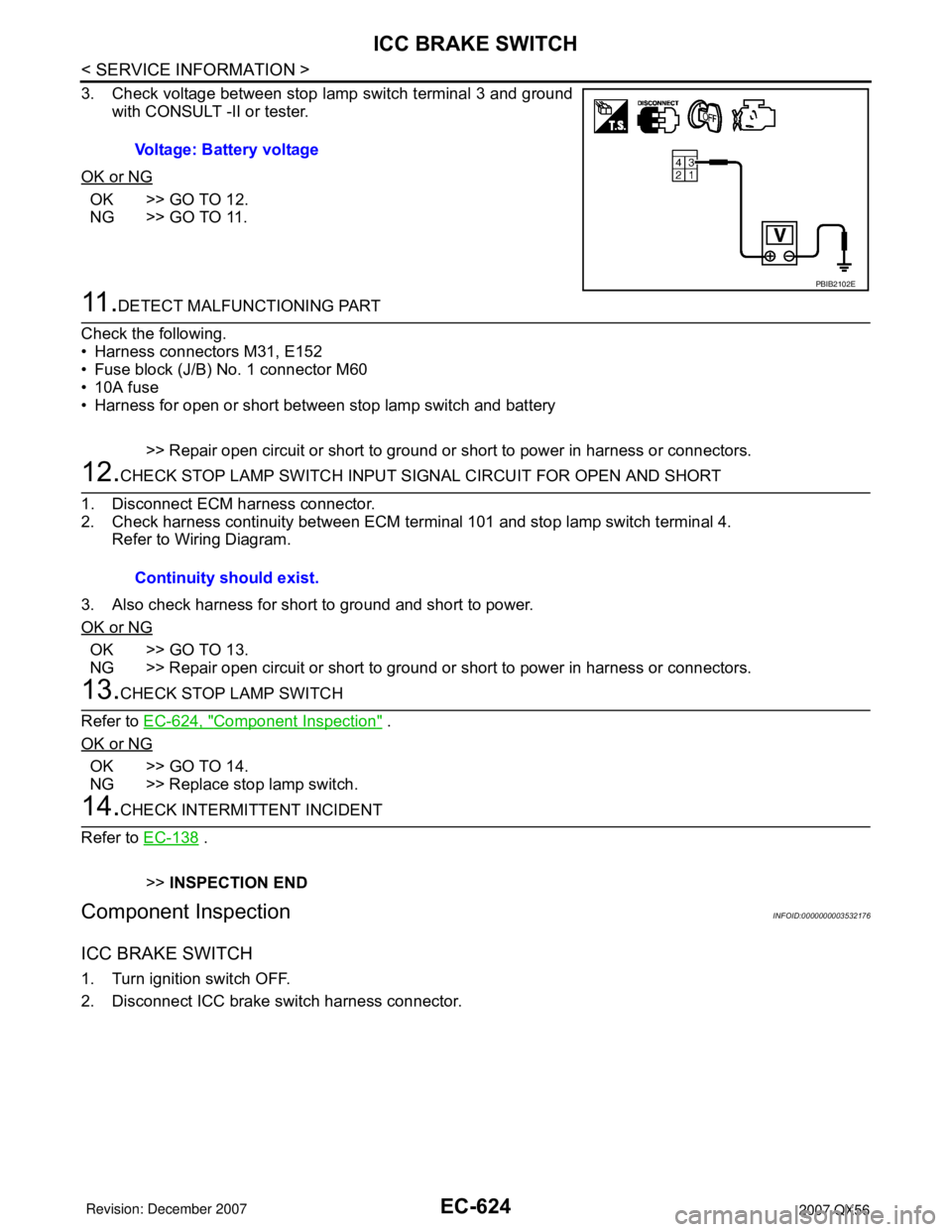
10.CHECK STOP LAMP SWITCH POWER SUPPLY CIRCUIT
1. Turn ignition switch OFF.
2. Disconnect stop lamp switch harness connector.Continuity should exist.
BBIA0470E
Continuity should exist.
BBIA0470E
Page 1707 of 3061
EC-624
< SERVICE INFORMATION >
ICC BRAKE SWITCH
3. Check voltage between stop lamp switch terminal 3 and ground
with CONSULT -II or tester.
OK or NG
OK >> GO TO 12.
NG >> GO TO 11.
11 .DETECT MALFUNCTIONING PART
Check the following.
• Harness connectors M31, E152
• Fuse block (J/B) No. 1 connector M60
• 10A fuse
• Harness for open or short between stop lamp switch and battery
>> Repair open circuit or short to ground or short to power in harness or connectors.
12.CHECK STOP LAMP SWITCH INPUT SIGNAL CIRCUIT FOR OPEN AND SHORT
1. Disconnect ECM harness connector.
2. Check harness continuity between ECM terminal 101 and stop lamp switch terminal 4.
Refer to Wiring Diagram.
3. Also check harness for short to ground and short to power.
OK or NG
OK >> GO TO 13.
NG >> Repair open circuit or short to ground or short to power in harness or connectors.
13.CHECK STOP LAMP SWITCH
Refer to EC-624, "
Component Inspection" .
OK or NG
OK >> GO TO 14.
NG >> Replace stop lamp switch.
14.CHECK INTERMITTENT INCIDENT
Refer to EC-138
.
>>INSPECTION END
Component InspectionINFOID:0000000003532176
ICC BRAKE SWITCH
1. Turn ignition switch OFF.
2. Disconnect ICC brake switch harness connector.Voltage: Battery voltage
PBIB2102E
Continuity should exist.
Page 1708 of 3061
ICC BRAKE SWITCH
EC-625
< SERVICE INFORMATION >
C
D
E
F
G
H
I
J
K
L
MA
EC
N
P O
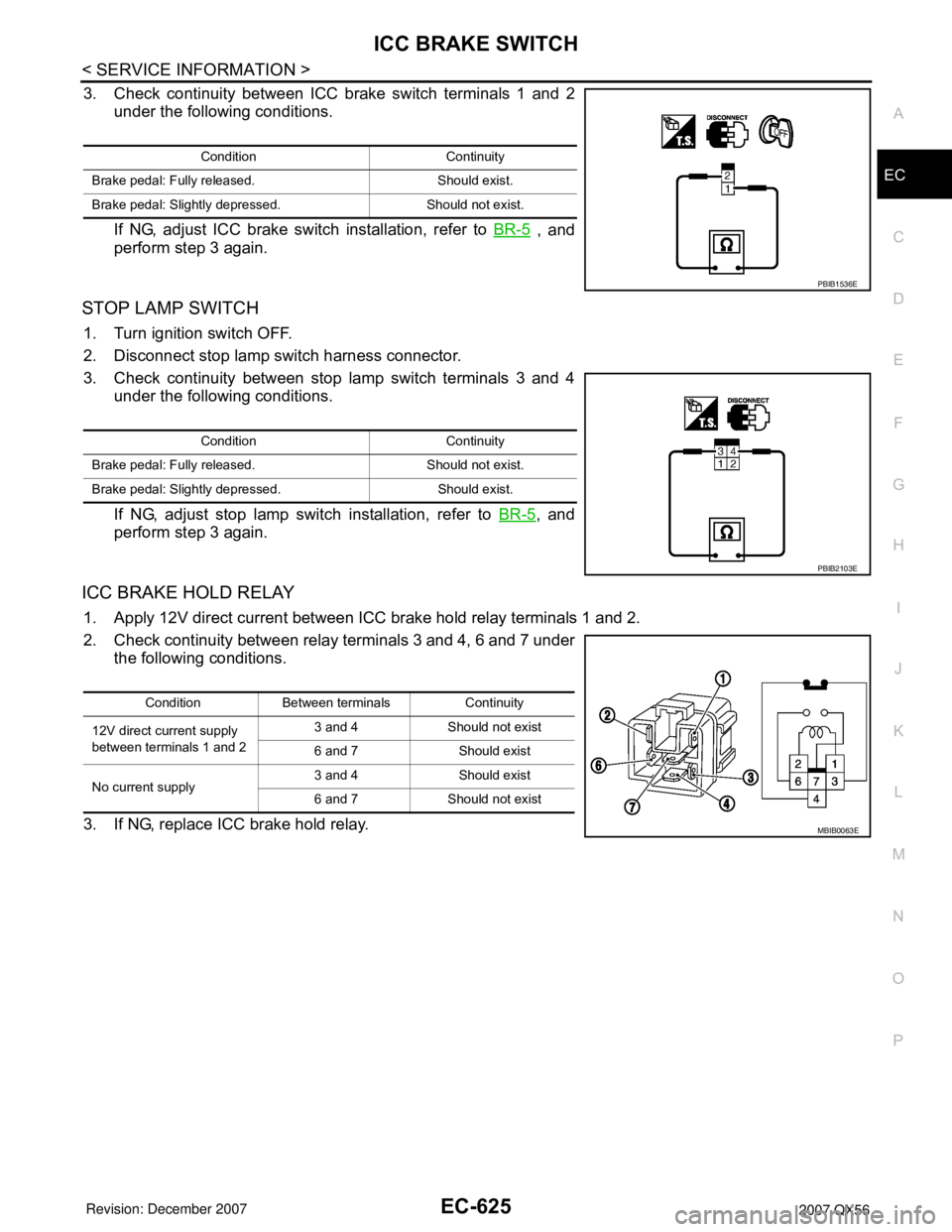
3. Check continuity between ICC brake switch terminals 1 and 2
under the following conditions.
If NG, adjust ICC brake switch installation, refer to BR-5
, and
perform step 3 again.
STOP LAMP SWITCH
1. Turn ignition switch OFF.
2. Disconnect stop lamp switch harness connector.
3. Check continuity between stop lamp switch terminals 3 and 4
under the following conditions.
If NG, adjust stop lamp switch installation, refer to BR-5
, and
perform step 3 again.
ICC BRAKE HOLD RELAY
1. Apply 12V direct current between ICC brake hold relay terminals 1 and 2.
2. Check continuity between relay terminals 3 and 4, 6 and 7 under
the following conditions.
3. If NG, replace ICC brake hold relay.
Condition Continuity
Brake pedal: Fully released. Should exist.
Brake pedal: Slightly depressed. Should not exist.
PBIB1536E
Condition Continuity
Brake pedal: Fully released. Should not exist.
Brake pedal: Slightly depressed. Should exist.
PBIB2103E
Condition Between terminals Continuity
12V direct current supply
between terminals 1 and 23 and 4 Should not exist
6 and 7 Should exist
No current supply3 and 4 Should exist
6 and 7 Should not exist
MBIB0063E
Page 1845 of 3061
ENGINE ASSEMBLY
EM-75
< SERVICE INFORMATION >
C
D
E
F
G
H
I
J
K
L
MA
EM
N
P O
6. Remove the engine room cover using power tools.
7. Remove the air duct and air cleaner case assembly. Refer to EM-15, "
Removal and Installation".
8. Disconnect the vacuum hose between the vehicle and engine and set it aside.
9. Remove the radiator assembly and hoses. Refer to CO-13, "
Removal and Installation".
10. Remove the drive belts. Refer to EM-15, "
Removal and Installation".
11. Remove the fan blade. Refer to CO-16, "
Removal and Installation (Crankshaft Driven Type)".
12. Disconnect the engine room harness from the fuse box and set it aside.
13. Disconnect the ECM.
14. Disconnect the engine room harness from the engine side and set it aside.
15. Disconnect the engine harness grounds.
16. Disconnect the power steering reservoir tank from the engine and move it aside.
17. Disconnect the power steering oil pump from the engine. Move it aside and secure it using suitable wire or
rope. Refer to PS-21, "
Removal and Installation".
18. Remove the A/C compressor bolts and set the compressor aside. Refer to ATC-154, "
Removal and Instal-
lation for Compressor" (ATC).
19. Disconnect the brake booster vacuum line.
20. Disconnect the EVAP line.
21. Disconnect the fuel hose at the engine side connection. Refer to EM-31, "
Removal and Installation".
22. Disconnect the heater hoses at the cowl, and install plugs to avoid leakage of engine coolant.
23. Remove the A/T oil level indicator and indicator tube upper bolts.
24. Remove the front final drive assembly (4WD only). Refer to FFD-12, "
Removal and Installation".
25. Remove the exhaust manifolds. Refer to EM-21, "
Removal and Installation".
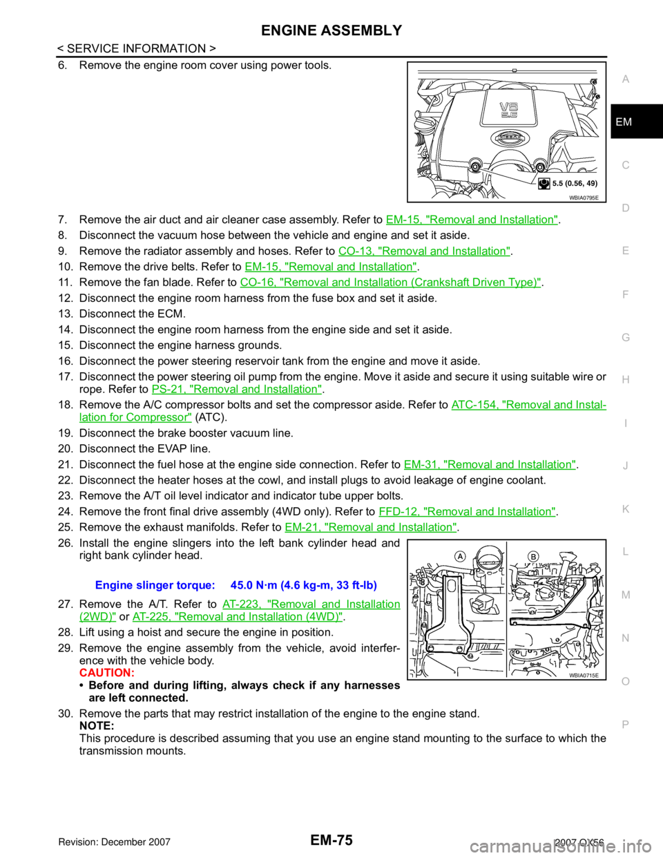
26. Install the engine slingers into the left bank cylinder head and
right bank cylinder head.
27. Remove the A/T. Refer to AT-223, "
Removal and Installation
(2WD)" or AT-225, "Removal and Installation (4WD)".
28. Lift using a hoist and secure the engine in position.
29. Remove the engine assembly from the vehicle, avoid interfer-
ence with the vehicle body.
CAUTION:
• Before and during lifting, always check if any harnesses
are left connected.
30. Remove the parts that may restrict installation of the engine to the engine stand.
NOTE:
This procedure is described assuming that you use an engine stand mounting to the surface to which the
transmission mounts.
WBIA0795E
Engine slinger torque: 45.0 N·m (4.6 kg-m, 33 ft-lb)
WBIA0715E
Page 1847 of 3061
ENGINE ASSEMBLY
EM-77
< SERVICE INFORMATION >
C
D
E
F
G
H
I
J
K
L
MA
EM
N
P O
• Start engine. With engine speed increased, check again for fuel leakage at connection points.
• Run engine to check for unusual noise and vibration.
• Warm up engine thoroughly to make sure there is no leakage of fuel, exhaust gas, or any oils/fluids including
engine oil and engine coolant.
• Bleed air from passages in lines and hoses, such as in cooling system.
• After cooling down the engine, again check oil/fluid levels including engine oil and engine coolant. Refill to
specified level if necessary.
• Summary of the inspection items:
*Transmission/transaxle/CVT fluid, power steering fluid, brake fluid, etc.Item Before starting engine Engine running After engine stopped
Engine coolant Level Leakage Level
Engine oil Level Leakage Level
Other oils and fluids* Level Leakage Level
Fuel Leakage Leakage Leakage
Exhaust gas — Leakage —