Page 2524 of 3061

RAX-6
< SERVICE INFORMATION >
WHEEL HUB
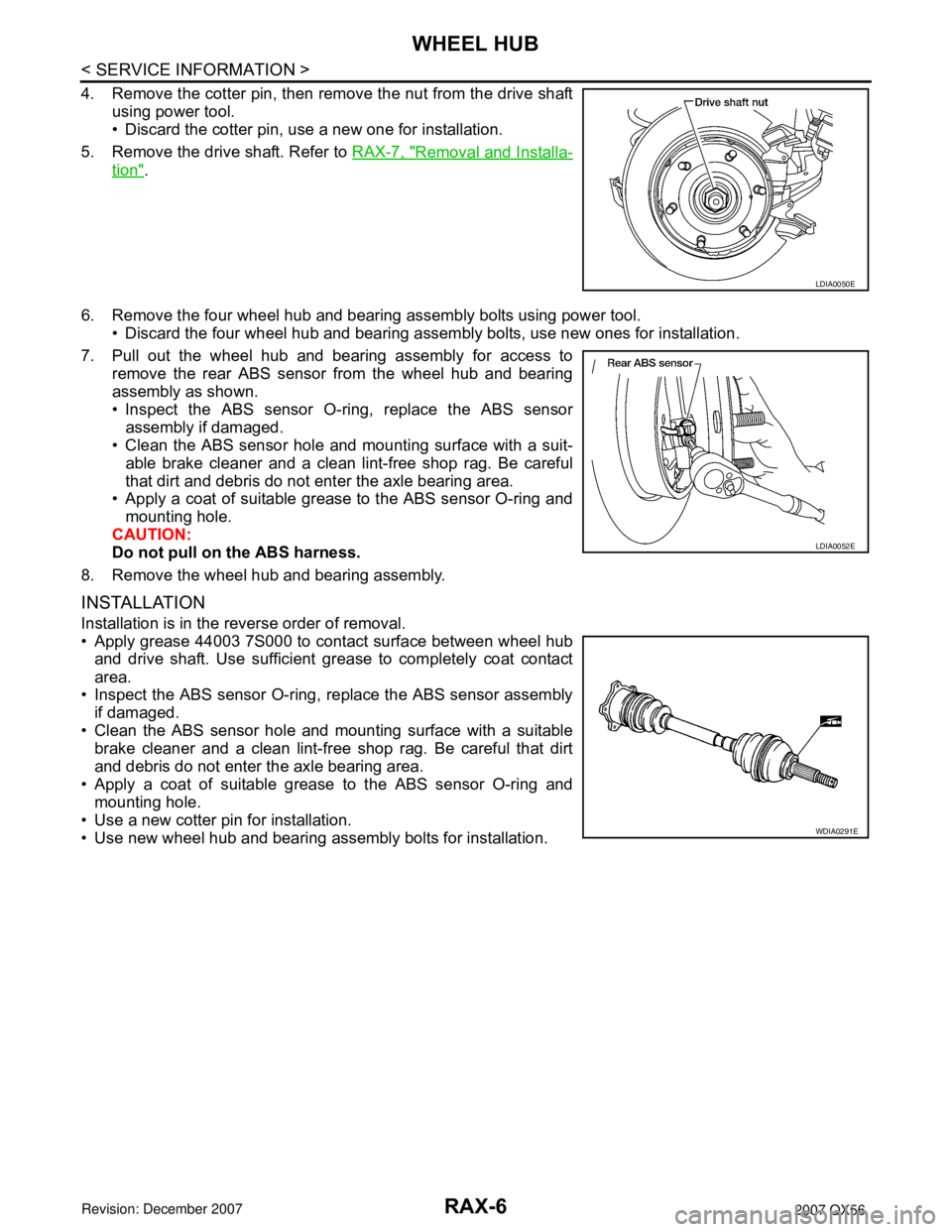
4. Remove the cotter pin, then remove the nut from the drive shaft
using power tool.
• Discard the cotter pin, use a new one for installation.
5. Remove the drive shaft. Refer to RAX-7, "
Removal and Installa-
tion".
6. Remove the four wheel hub and bearing assembly bolts using power tool.
• Discard the four wheel hub and bearing assembly bolts, use new ones for installation.
7. Pull out the wheel hub and bearing assembly for access to
remove the rear ABS sensor from the wheel hub and bearing
assembly as shown.
• Inspect the ABS sensor O-ring, replace the ABS sensor
assembly if damaged.
• Clean the ABS sensor hole and mounting surface with a suit-
able brake cleaner and a clean lint-free shop rag. Be careful
that dirt and debris do not enter the axle bearing area.
• Apply a coat of suitable grease to the ABS sensor O-ring and
mounting hole.
CAUTION:
Do not pull on the ABS harness.
8. Remove the wheel hub and bearing assembly.
INSTALLATION
Installation is in the reverse order of removal.
• Apply grease 44003 7S000 to contact surface between wheel hub
and drive shaft. Use sufficient grease to completely coat contact
area.
• Inspect the ABS sensor O-ring, replace the ABS sensor assembly
if damaged.
• Clean the ABS sensor hole and mounting surface with a suitable
brake cleaner and a clean lint-free shop rag. Be careful that dirt
and debris do not enter the axle bearing area.
• Apply a coat of suitable grease to the ABS sensor O-ring and
mounting hole.
• Use a new cotter pin for installation.
• Use new wheel hub and bearing assembly bolts for installation.
LDIA0050E
LDIA0052E
WDIA0291E
Page 2525 of 3061
REAR DRIVE SHAFT
RAX-7
< SERVICE INFORMATION >
C
E
F
G
H
I
J
K
L
MA
B
RAX
N
O
P
REAR DRIVE SHAFT
ComponentINFOID:0000000003532626
Rear Drive Shaft
Removal and InstallationINFOID:0000000003532627
REMOVAL
1. Remove the wheel and tire using power tool.
2. Remove the stabilizer bar clamp. Refer to RSU-21, "
Component".
3. Remove the cotter pin and discard, then remove the drive shaft
nut from the drive shaft.
• Do not reuse the cotter pin, discard after removal and use a
new cotter pin for installation.
4. Remove the six bolts from the inside flange of the drive shaft using power tool.
• Do not reuse the drive shaft inside flange bolts, discard after removal and use new bolts for installation.
WDIA0263E
1. Rear final drive assembly 2. Rear drive shaft 3. Rear brake and hub assembly
4. Cotter pin
LDIA0050E
Page 2526 of 3061

RAX-8
< SERVICE INFORMATION >
REAR DRIVE SHAFT
5. Separate the drive shaft from the wheel hub and bearing assembly by lightly tapping the end with a suit-
able hammer and wood block. If it is difficult to separate, use a suitable puller.
6. Remove the drive shaft.
CAUTION:
When removing the drive shaft, do not bend at an excessive angle to the drive shaft joint. Do not
excessively extend the slide joint.
INSPECTION AFTER REMOVAL
• Move the joint up and down, left and right, and in the axial direc-
tion. Check for any rough movement or significant looseness.
• Check the boot for cracks or other damage, and for any grease
leakage.
• If necessary, disassemble the drive shaft, and repair as necessary.
INSTALLATION
Installation is in the reverse order of removal.
• Do not reuse the drive shaft inside flange bolts, discard after removal and use new bolts for installation.
• Do not reuse the cotter pin, discard after removal and use a new cotter pin for installation.
Disassembly and AssemblyINFOID:0000000003532628
DISASSEMBLY
Final Drive Side
1. Mount the drive shaft in a vise.
CAUTION:
RAA0030D
Drive shaft lock nut : Refer to RAX-7, "Component".
Drive shaft inside flange bolts : Refer to RAX-7, "
Component".
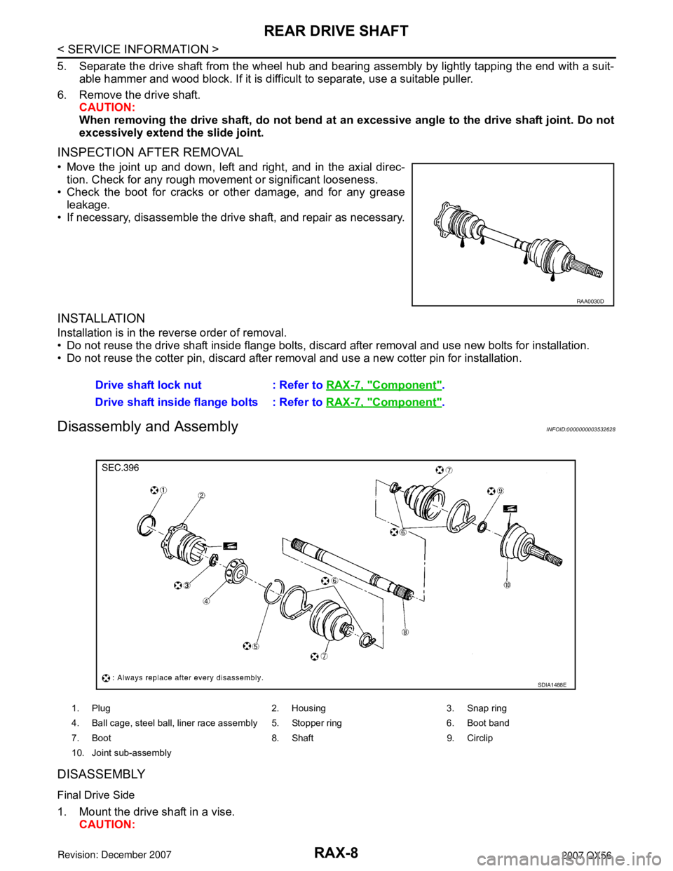
1. Plug 2. Housing 3. Snap ring
4. Ball cage, steel ball, liner race assembly 5. Stopper ring 6. Boot band
7. Boot 8. Shaft 9. Circlip
10. Joint sub-assembly
SDIA1488E
Page 2614 of 3061

RSU-24
< SERVICE INFORMATION >
REAR SUSPENSION ASSEMBLY
• Check with the manufacturer of your specific alignment machine for their recommended Service/Cali-
bration Schedule.
THE ALIGNMENT PROCESS
IMPORTANT: Use only the alignment specifications listed in this Service Manual. Refer to FSU-19, "Wheel
Alignment (Unladen*1) *6" .
1. When displaying the alignment settings, many alignment machines use “indicators”: (Green/red, plus or
minus, Go/No Go). Do NOT use these indicators.
• The alignment specifications programmed into your alignment machine that operate these indicators
may not be correct.
• This may result in an ERROR.
2. Some newer alignment machines are equipped with an optional “Rolling Compensation” method to “com-
pensate” the sensors (alignment targets or head units). Do NOT use this “Rolling Compensation”
method.
• Use the “Jacking Compensation” method. After installing the alignment targets or head units, raise the
vehicle and rotate the wheels 1/2 turn both ways.
• See Instructions in the alignment machine you are using for more information.
CAMBER
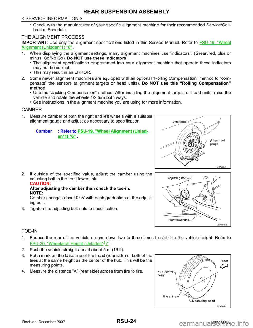
1. Measure camber of both the right and left wheels with a suitable
alignment gauge and adjust as necessary to specification.
2. If outside of the specified value, adjust the camber using the
adjusting bolt in the front lower link.
CAUTION:
After adjusting the camber then check the toe-in.
NOTE:
Camber changes about 0° 5' with each graduation of the adjust-
ing bolt.
3. Tighten the adjusting bolt nuts to specification.
TOE-IN
1. Bounce the rear of the vehicle up and down two to three times to stabilize the vehicle height. Refer to
FSU-20, "
Wheelarch Height (Unladen*1)" .
2. Push the vehicle straight ahead about 5 m (16 ft).
3. Put a mark on the base line of the tread (rear side) of both of the
tires at the same height as the center of the hub. This will be the
measuring points.
4. Measure the distance “A” (rear side) across from tire to tire.Camber : Refer to FSU-19, "
Wheel Alignment (Unlad-
en*1) *6" .
SRA096A
LEIA0041E
SFA614B
Page 2834 of 3061
TF-12
< SERVICE INFORMATION >
ALL-MODE 4WD SYSTEM
ALL-MODE 4WD SYSTEM
Cross-Sectional ViewINFOID:0000000003532515
Power TransferINFOID:0000000003532516
POWER TRANSFER DIAGRAM
1. Center case 2. Front case 3. Internal gear
4. Planetary carrier assembly 5. Sun gear assembly 6. Main shaft
7. L-H sleeve 8. L-H fork 9. Shift rod
10. 2-4 sleeve 11. 2-4 fork 12. Drive chain
13. Front drive shaft 14. Control valve assembly 15. Transfer motor
16. Rear case 17. Clutch piston 18. Press flange
19. Multiple disc clutch 20. Clutch hub assembly 21. Clutch drum assembly
WDIA0202E
Page 2835 of 3061
ALL-MODE 4WD SYSTEM
TF-13
< SERVICE INFORMATION >
C
E
F
G
H
I
J
K
L
MA
B
TF
N
O
P
POWER TRANSFER FLOW
1. Center case 2. Chain 3. Multiple disc clutch
4. Rear case 5. Mainshaft 6. Clutch hub assembly
7. Sub oil pump 8. Transfer motor 9. Control valve
10. Front drive shaft 11. Drain plug 12. 2-4 sleeve
13. Sun gear assembly 14. L-H sleeve 15. Planetary carrier assembly
16. Internal gear 17. Front case
LDIA0053E
Page 2951 of 3061

TRANSFER ASSEMBLY
TF-129
< SERVICE INFORMATION >
C
E
F
G
H
I
J
K
L
MA
B
TF
N
O
P
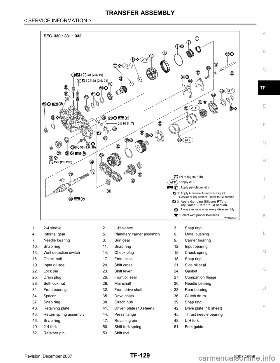
1. 2-4 sleeve 2. L-H sleeve 3. Snap ring
4. Internal gear 5. Planetary carrier assembly 6. Metal bushing
7. Needle bearing 8. Sun gear 9. Carrier bearing
10. Snap ring 11. Snap ring 12. Input bearing
13. Wait detection switch 14. Check plug 15. Check spring
16. Check ball 17. Front case 18. Snap ring
19. Input oil seal 20. Shift cross 21. Side oil seal
22. Lock pin 23. Shift lever 24. Gasket
25. Drain plug 26. Front oil seal 27. Companion flange
28. Self-lock nut 29. Mainshaft 30. Needle bearing
31. Front bearing 32. Front drive shaft 33. Rear bearing
34. Spacer 35. Drive chain 36. Clutch drum
37. Snap ring 38. Clutch hub 39. Snap ring
40. Retaining plate 41. Driven plate (10 sheet) 42. Drive plate (10 sheet)
43. Return spring assembly 44. Press flange 45. Thrust needle bearing
46. Snap ring 47. Retaining pin 48. L-H fork
49. 2-4 fork 50. Shift fork spring 51. Fork guide
52. Retainer pin 53. Shift rod
WDIA0194E
Page:
< prev 1-8 9-16 17-24