Page 1237 of 3061
EC-154
< SERVICE INFORMATION >
DTC P0011, P0021 IVT CONTROL
BANK 2
Specification data are reference values and are measured between each terminal and ground.
Pulse signal is measured by CONSULT-II.
CAUTION:
Do not use ECM ground terminals when measuring input/output voltage. Doing so may result in dam-
age to the ECM's transistor. Use a ground other than ECM terminals, such as the ground.
BBWA2797E
Page 1238 of 3061
DTC P0011, P0021 IVT CONTROL
EC-155
< SERVICE INFORMATION >
C
D
E
F
G
H
I
J
K
L
MA
EC
N
P O
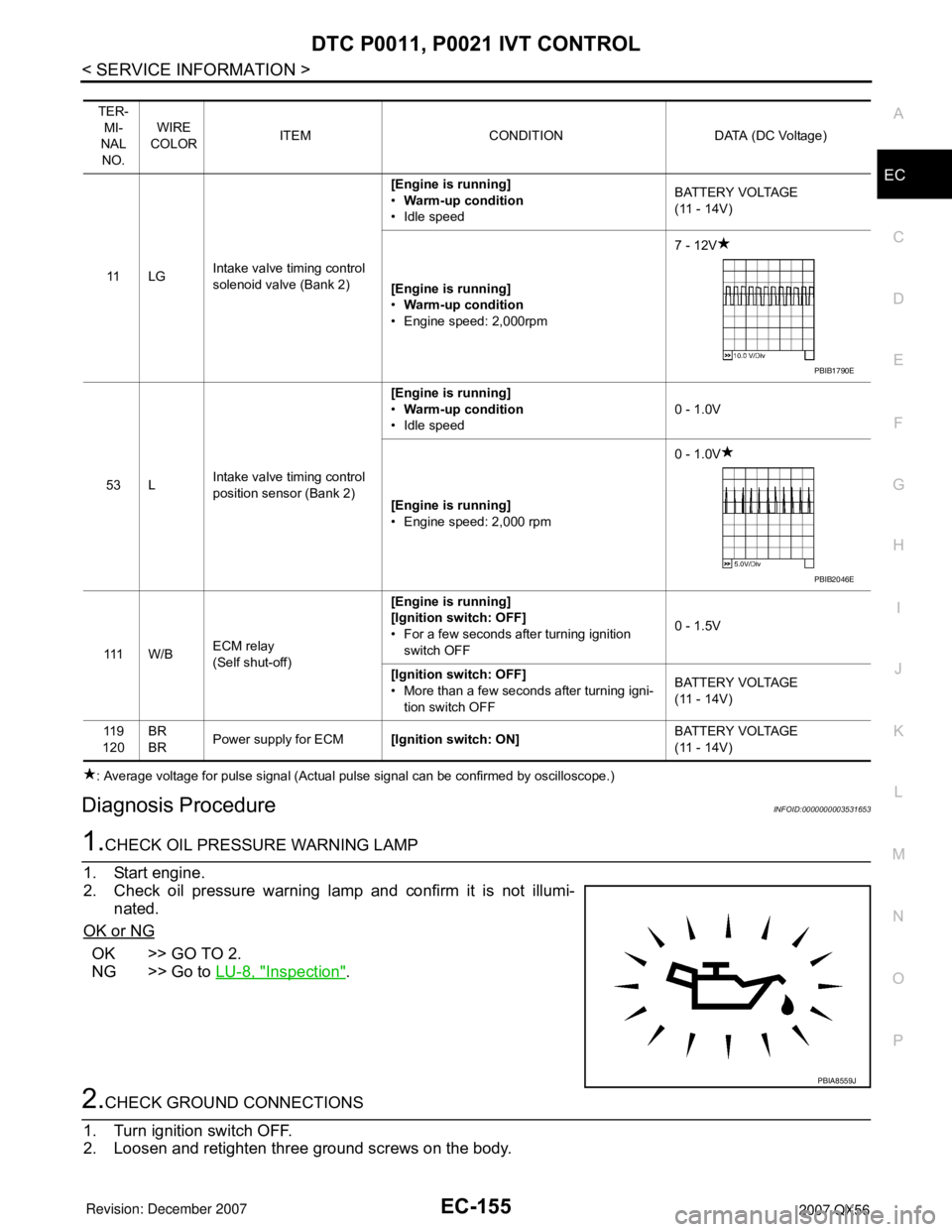
: Average voltage for pulse signal (Actual pulse signal can be confirmed by oscilloscope.)
Diagnosis ProcedureINFOID:0000000003531653
1.CHECK OIL PRESSURE WARNING LAMP
1. Start engine.
2. Check oil pressure warning lamp and confirm it is not illumi-
nated.
OK or NG
OK >> GO TO 2.
NG >> Go to LU-8, "
Inspection".
2.CHECK GROUND CONNECTIONS
1. Turn ignition switch OFF.
2. Loosen and retighten three ground screws on the body.
TER-
MI-
NAL
NO.WIRE
COLORITEM CONDITION DATA (DC Voltage)
11 L GIntake valve timing control
solenoid valve (Bank 2)[Engine is running]
•Warm-up condition
• Idle speedBATTERY VOLTAGE
(11 - 14V)
[Engine is running]
•Warm-up condition
• Engine speed: 2,000rpm7 - 12V
53 LIntake valve timing control
position sensor (Bank 2)[Engine is running]
•Warm-up condition
• Idle speed0 - 1.0V
[Engine is running]
• Engine speed: 2,000 rpm0 - 1.0V
111 W / BECM relay
(Self shut-off)[Engine is running]
[Ignition switch: OFF]
• For a few seconds after turning ignition
switch OFF0 - 1.5V
[Ignition switch: OFF]
• More than a few seconds after turning igni-
tion switch OFFBATTERY VOLTAGE
(11 - 14V)
11 9
120BR
BRPower supply for ECM[Ignition switch: ON]BATTERY VOLTAGE
(11 - 14V)
PBIB1790E
PBIB2046E
PBIA8559J
Page 1239 of 3061
EC-156
< SERVICE INFORMATION >
DTC P0011, P0021 IVT CONTROL
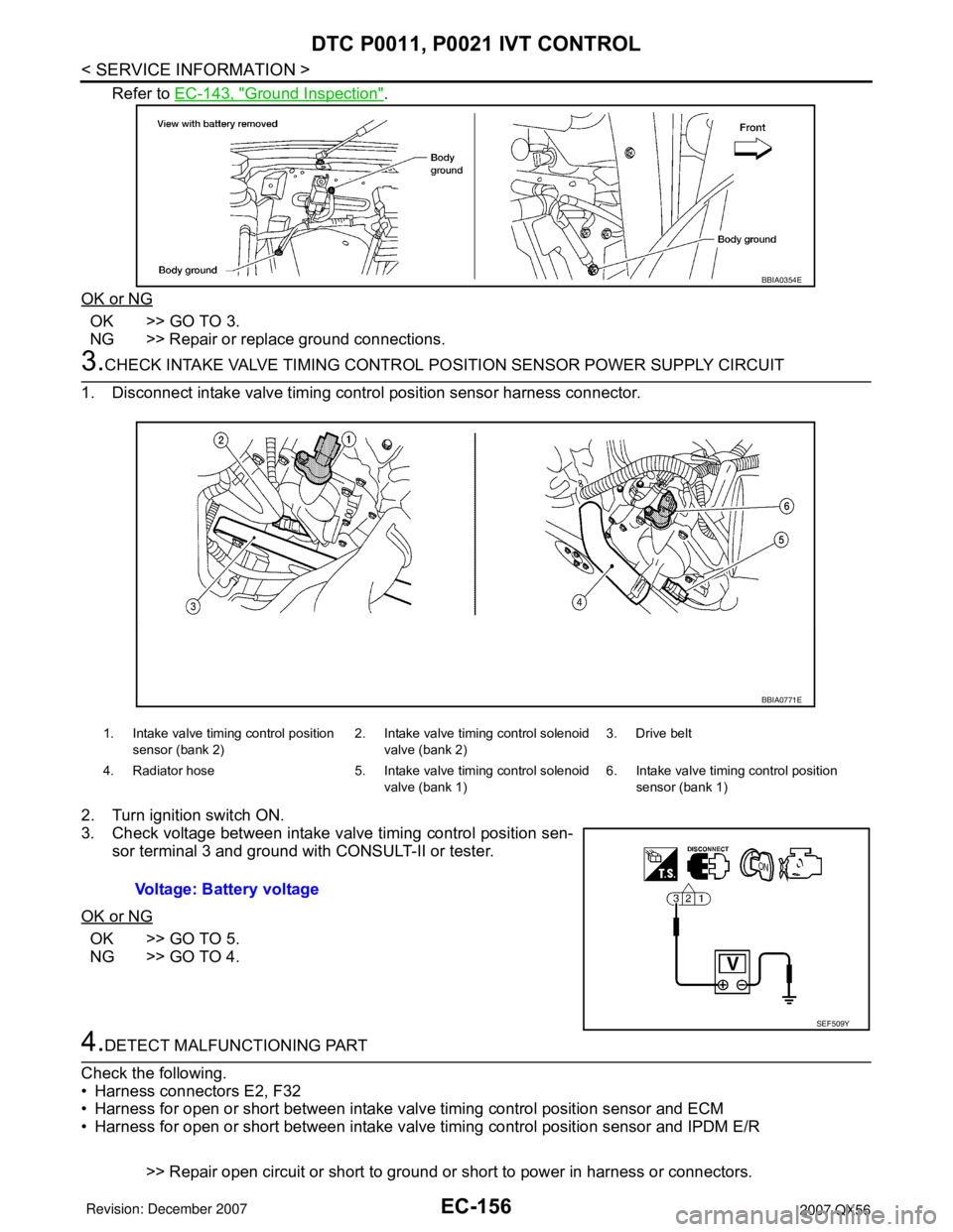
Refer to EC-143, "Ground Inspection".
OK or NG
OK >> GO TO 3.
NG >> Repair or replace ground connections.
3.CHECK INTAKE VALVE TIMING CONTROL POSITION SENSOR POWER SUPPLY CIRCUIT
1. Disconnect intake valve timing control position sensor harness connector.
2. Turn ignition switch ON.
3. Check voltage between intake valve timing control position sen-
sor terminal 3 and ground with CONSULT-II or tester.
OK or NG
OK >> GO TO 5.
NG >> GO TO 4.
4.DETECT MALFUNCTIONING PART
Check the following.
• Harness connectors E2, F32
• Harness for open or short between intake valve timing control position sensor and ECM
• Harness for open or short between intake valve timing control position sensor and IPDM E/R
>> Repair open circuit or short to ground or short to power in harness or connectors.
BBIA0354E
1. Intake valve timing control position
sensor (bank 2)2. Intake valve timing control solenoid
valve (bank 2)3. Drive belt
4. Radiator hose 5. Intake valve timing control solenoid
valve (bank 1)6. Intake valve timing control position
sensor (bank 1)
Voltage: Battery voltage
BBIA0771E
SEF509Y
Page 1240 of 3061
DTC P0011, P0021 IVT CONTROL
EC-157
< SERVICE INFORMATION >
C
D
E
F
G
H
I
J
K
L
MA
EC
N
P O
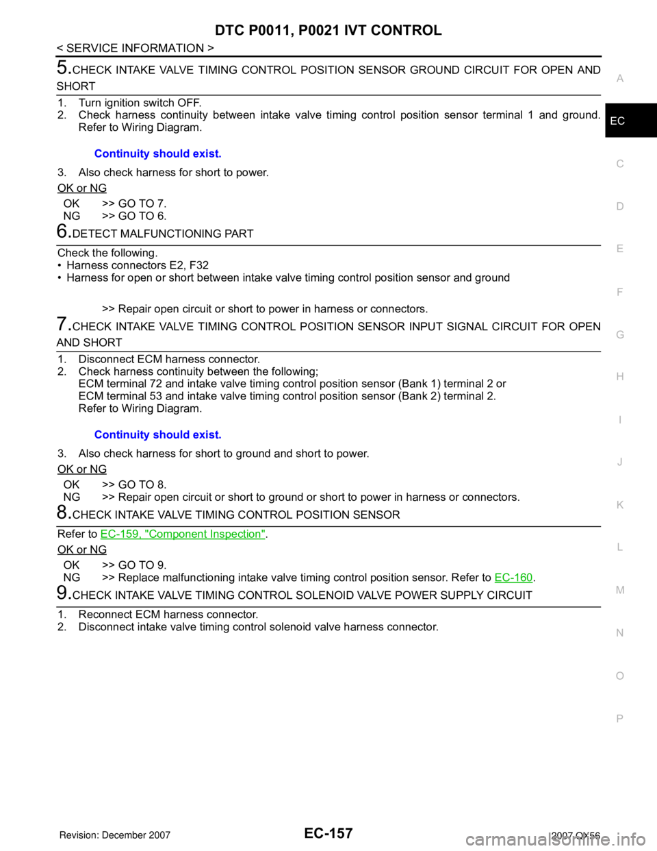
5.CHECK INTAKE VALVE TIMING CONTROL POSITION SENSOR GROUND CIRCUIT FOR OPEN AND
SHORT
1. Turn ignition switch OFF.
2. Check harness continuity between intake valve timing control position sensor terminal 1 and ground.
Refer to Wiring Diagram.
3. Also check harness for short to power.
OK or NG
OK >> GO TO 7.
NG >> GO TO 6.
6.DETECT MALFUNCTIONING PART
Check the following.
• Harness connectors E2, F32
• Harness for open or short between intake valve timing control position sensor and ground
>> Repair open circuit or short to power in harness or connectors.
7.CHECK INTAKE VALVE TIMING CONTROL POSITION SENSOR INPUT SIGNAL CIRCUIT FOR OPEN
AND SHORT
1. Disconnect ECM harness connector.
2. Check harness continuity between the following;
ECM terminal 72 and intake valve timing control position sensor (Bank 1) terminal 2 or
ECM terminal 53 and intake valve timing control position sensor (Bank 2) terminal 2.
Refer to Wiring Diagram.
3. Also check harness for short to ground and short to power.
OK or NG
OK >> GO TO 8.
NG >> Repair open circuit or short to ground or short to power in harness or connectors.
8.CHECK INTAKE VALVE TIMING CONTROL POSITION SENSOR
Refer to EC-159, "
Component Inspection".
OK or NG
OK >> GO TO 9.
NG >> Replace malfunctioning intake valve timing control position sensor. Refer to EC-160
.
9.CHECK INTAKE VALVE TIMING CONTROL SOLENOID VALVE POWER SUPPLY CIRCUIT
1. Reconnect ECM harness connector.
2. Disconnect intake valve timing control solenoid valve harness connector.Continuity should exist.
Continuity should exist.
Page 1241 of 3061
EC-158
< SERVICE INFORMATION >
DTC P0011, P0021 IVT CONTROL
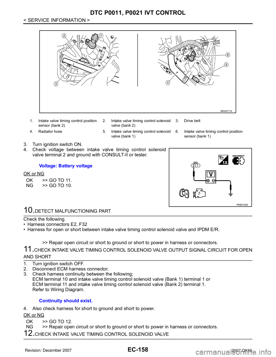
3. Turn ignition switch ON.
4. Check voltage between intake valve timing control solenoid
valve terminal 2 and ground with CONSULT-II or tester.
OK or NG
OK >> GO TO 11.
NG >> GO TO 10.
10.DETECT MALFUNCTIONING PART
Check the following.
• Harness connectors E2, F32
• Harness for open or short between intake valve timing control solenoid valve and IPDM E/R.
>> Repair open circuit or short to ground or short to power in harness or connectors.
11 .CHECK INTAKE VALVE TIMING CONTROL SOLENOID VALVE OUTPUT SIGNAL CIRCUIT FOR OPEN
AND SHORT
1. Turn ignition switch OFF.
2. Disconnect ECM harness connector.
3. Check harness continuity between the following;
ECM terminal 10 and intake valve timing control solenoid valve (Bank 1) terminal 1 or
ECM terminal 11 and intake valve timing control solenoid valve (Bank 2) terminal 1.
Refer to Wiring Diagram.
4. Also check harness for short to ground and short to power.
OK or NG
OK >> GO TO 12.
NG >> Repair open circuit or short to ground or short to power in harness or connectors.
12.CHECK INTAKE VALVE TIMING CONTROL SOLENOID VALVE
1. Intake valve timing control position
sensor (bank 2)2. Intake valve timing control solenoid
valve (bank 2)3. Drive belt
4. Radiator hose 5. Intake valve timing control solenoid
valve (bank 1)6. Intake valve timing control position
sensor (bank 1)
Voltage: Battery voltage
BBIA0771E
PBIB0192E
Continuity should exist.
Page 1242 of 3061
DTC P0011, P0021 IVT CONTROL
EC-159
< SERVICE INFORMATION >
C
D
E
F
G
H
I
J
K
L
MA
EC
N
P O
Refer to EC-159, "Component Inspection".
OK or NG
OK >> GO TO 13.
NG >> Replace malfunctioning intake valve timing control solenoid valve. Refer to EC-160
.
13.CHECK CRANKSHAFT POSITION SENSOR (POS)
Refer to EC-341, "
Component Inspection".
OK or NG
OK >> GO TO 14.
NG >> Replace crankshaft position sensor (POS).
14.CHECK CAMSHAFT POSITION SENSOR (PHASE)
Refer to EC-347, "
Component Inspection".
OK or NG
OK >> GO TO 15.
NG >> Replace malfunctioning camshaft position sensor (PHASE). Refer to EC-348
.
15.CHECK CAMSHAFT SPROCKET
Check accumulation of debris to the signal pick-up portion of the camshaft sprocket. Refer to EM-46
.
OK or NG
OK >> GO TO 16.
NG >> Remove debris and clean the signal pick-up cutout of camshaft sprocket.
16.CHECK TIMING CHAIN INSTALLATION
Check service records for any recent repairs that may cause timing chain misaligned.
Are there any service records that may cause timing chain misaligned?
Ye s o r N o
Yes >> Check timing chain installation. Refer to EM-38.
No >> GO TO 17.
17.CHECK LUBRICATION CIRCUIT
Refer to EM-55, "
Inspection after Installation".
OK or NG
OK >> GO TO 18.
NG >> Clean lubrication line.
18.CHECK INTERMITTENT INCIDENT
Refer to EC-138
.
>>INSPECTION END
Component InspectionINFOID:0000000003531654
INTAKE VALVE TIMING CONTROL POSITION SENSOR
1. Disconnect intake valve timing control position sensor harness connector.
2. Loosen the fixing bolt of the sensor.
3. Remove the sensor.
Page 1243 of 3061
EC-160
< SERVICE INFORMATION >
DTC P0011, P0021 IVT CONTROL
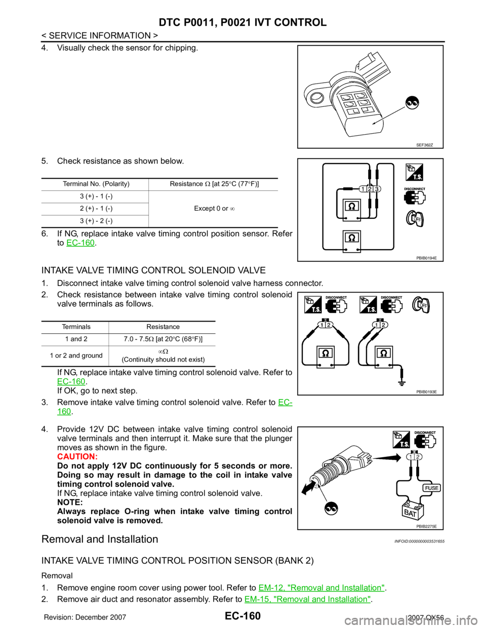
4. Visually check the sensor for chipping.
5. Check resistance as shown below.
6. If NG, replace intake valve timing control position sensor. Refer
to EC-160
.
INTAKE VALVE TIMING CONTROL SOLENOID VALVE
1. Disconnect intake valve timing control solenoid valve harness connector.
2. Check resistance between intake valve timing control solenoid
valve terminals as follows.
If NG, replace intake valve timing control solenoid valve. Refer to
EC-160
.
If OK, go to next step.
3. Remove intake valve timing control solenoid valve. Refer to EC-
160.
4. Provide 12V DC between intake valve timing control solenoid
valve terminals and then interrupt it. Make sure that the plunger
moves as shown in the figure.
CAUTION:
Do not apply 12V DC continuously for 5 seconds or more.
Doing so may result in damage to the coil in intake valve
timing control solenoid valve.
If NG, replace intake valve timing control solenoid valve.
NOTE:
Always replace O-ring when intake valve timing control
solenoid valve is removed.
Removal and InstallationINFOID:0000000003531655
INTAKE VALVE TIMING CONTROL POSITION SENSOR (BANK 2)
Removal
1. Remove engine room cover using power tool. Refer to EM-12, "Removal and Installation".
2. Remove air duct and resonator assembly. Refer to EM-15, "
Removal and Installation".
SEF362Z
Terminal No. (Polarity) Resistance Ω [at 25°C (77°F)]
3 (+) - 1 (-)
Except 0 or ∞ 2 (+) - 1 (-)
3 (+) - 2 (-)
PBIB0194E
Terminals Resistance
1 and 2 7.0 - 7.5Ω [at 20°C (68°F)]
1 or 2 and ground∞Ω
(Continuity should not exist)
PBIB0193E
PBIB2275E
Page 1244 of 3061
DTC P0011, P0021 IVT CONTROL
EC-161
< SERVICE INFORMATION >
C
D
E
F
G
H
I
J
K
L
MA
EC
N
P O
3. Disconnect intake valve timing control position sensor (bank 2) connector.
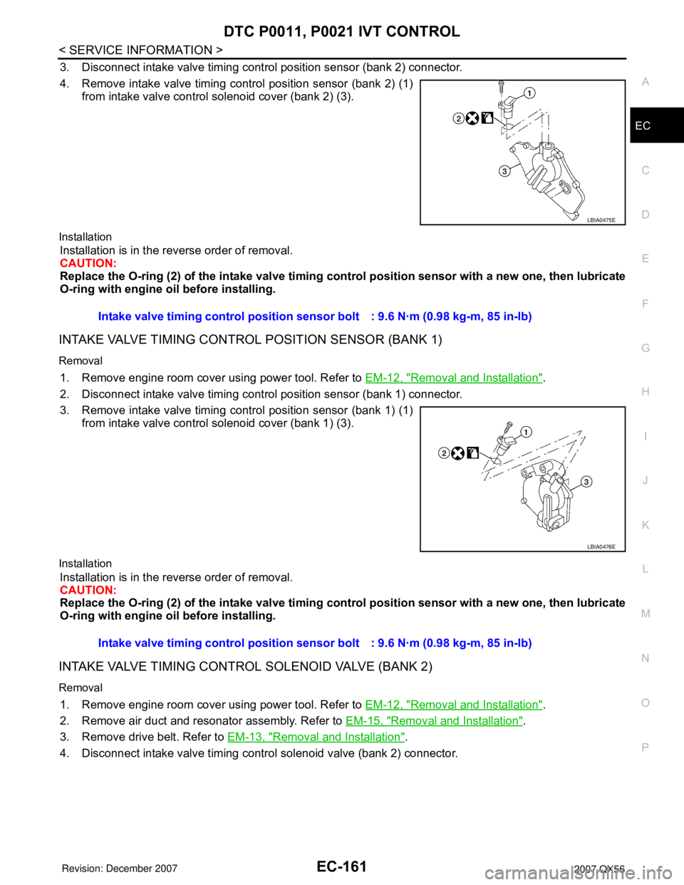
4. Remove intake valve timing control position sensor (bank 2) (1)
from intake valve control solenoid cover (bank 2) (3).
Installation
Installation is in the reverse order of removal.
CAUTION:
Replace the O-ring (2) of the intake valve timing control position sensor with a new one, then lubricate
O-ring with engine oil before installing.
INTAKE VALVE TIMING CONTROL POSITION SENSOR (BANK 1)
Removal
1. Remove engine room cover using power tool. Refer to EM-12, "Removal and Installation".
2. Disconnect intake valve timing control position sensor (bank 1) connector.
3. Remove intake valve timing control position sensor (bank 1) (1)
from intake valve control solenoid cover (bank 1) (3).
Installation
Installation is in the reverse order of removal.
CAUTION:
Replace the O-ring (2) of the intake valve timing control position sensor with a new one, then lubricate
O-ring with engine oil before installing.
INTAKE VALVE TIMING CONTROL SOLENOID VALVE (BANK 2)
Removal
1. Remove engine room cover using power tool. Refer to EM-12, "Removal and Installation".
2. Remove air duct and resonator assembly. Refer to EM-15, "
Removal and Installation".
3. Remove drive belt. Refer to EM-13, "
Removal and Installation".
4. Disconnect intake valve timing control solenoid valve (bank 2) connector.
LBIA0475E
Intake valve timing control position sensor bolt : 9.6 N·m (0.98 kg-m, 85 in-lb)
LBIA0476E
Intake valve timing control position sensor bolt : 9.6 N·m (0.98 kg-m, 85 in-lb)