Page 1176 of 3061

TROUBLE DIAGNOSIS
EC-93
< SERVICE INFORMATION >
C
D
E
F
G
H
I
J
K
L
MA
EC
N
P O
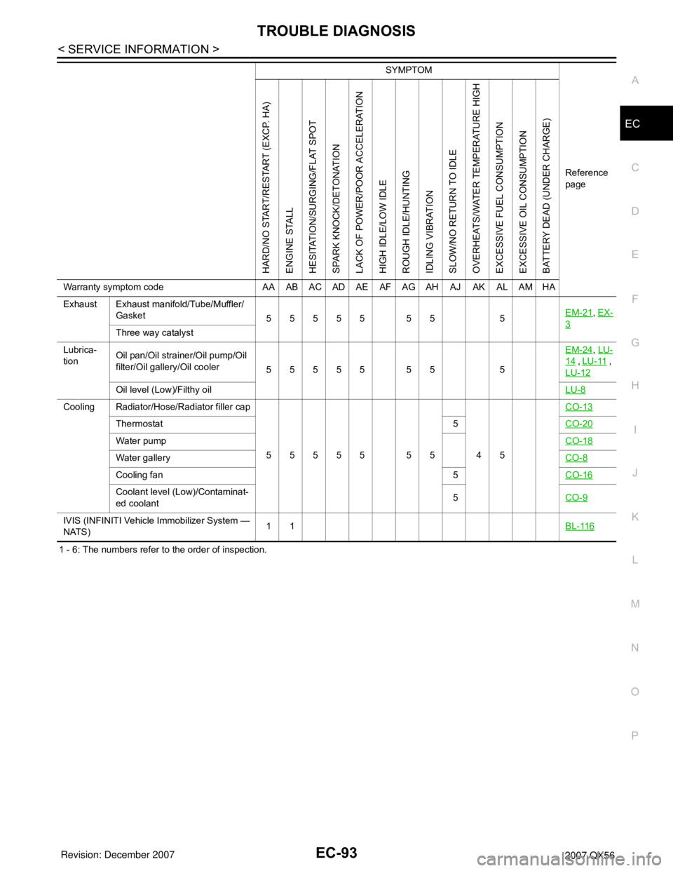
1 - 6: The numbers refer to the order of inspection.Exhaust Exhaust manifold/Tube/Muffler/
Gasket
55555 55 5EM-21
, EX-
3Three way catalyst
Lubrica-
tionOil pan/Oil strainer/Oil pump/Oil
filter/Oil gallery/Oil cooler
55555 55 5EM-24
, LU-
14 , LU-11 ,
LU-12
Oil level (Low)/Filthy oilLU-8
Cooling Radiator/Hose/Radiator filler cap
55555 55 45CO-13
Thermostat 5CO-20
Water pumpCO-18
Water galleryCO-8
Cooling fan 5CO-16
Coolant level (Low)/Contaminat-
ed coolant5CO-9
IVIS (INFINITI Vehicle Immobilizer System —
NATS)11BL-116
SYMPTOM
Reference
page
HARD/NO START/RESTART (EXCP. HA)
ENGINE STALL
HESITATION/SURGING/FLAT SPOT
SPARK KNOCK/DETONATION
LACK OF POWER/POOR ACCELERATION
HIGH IDLE/LOW IDLE
ROUGH IDLE/HUNTING
IDLING VIBRATION
SLOW/NO RETURN TO IDLE
OVERHEATS/WATER TEMPERATURE HIGH
EXCESSIVE FUEL CONSUMPTION
EXCESSIVE OIL CONSUMPTION
BATTERY DEAD (UNDER CHARGE)
Warranty symptom code AA AB AC AD AE AF AG AH AJ AK AL AM HA
Page 1396 of 3061
DTC P0181 FTT SENSOR
EC-313
< SERVICE INFORMATION >
C
D
E
F
G
H
I
J
K
L
MA
EC
N
P O
NG >> Replace “fuel level sensor unit and fuel pump”.
6.CHECK INTERMITTENT INCIDENT
Refer to EC-138
.
>>INSPECTION END
Component InspectionINFOID:0000000003531805
FUEL TANK TEMPERATURE SENSOR
1. Remove fuel level sensor unit.
2. Check resistance between “fuel level sensor unit and fuel pump”
terminals 3 and 4 by heating with hot water as shown in the fig-
ure.
If NG, replace fuel level sensor unit.
Removal and InstallationINFOID:0000000003531806
FUEL TANK TEMPERATURE SENSOR
Refer to FL-5.
Temperature °C (°F) Resistance kΩ
20 (68) 2.3 - 2.7
50 (122) 0.79 - 0.90
SEF476YA
Page 1400 of 3061
DTC P0182, P0183 FTT SENSOR
EC-317
< SERVICE INFORMATION >
C
D
E
F
G
H
I
J
K
L
MA
EC
N
P O
>>INSPECTION END
Component InspectionINFOID:0000000003531812
FUEL TANK TEMPERATURE SENSOR
1. Remove fuel level sensor unit.
2. Check resistance between “fuel level sensor unit and fuel pump”
terminals 3 and 4 by heating with hot water as shown in the fig-
ure.
If NG, replace fuel level sensor unit.
Removal and InstallationINFOID:0000000003531813
FUEL TANK TEMPERATURE SENSOR
Refer to FL-5.
Temperature °C (°F) Resistance kΩ
20 (68) 2.3 - 2.7
50 (122) 0.79 - 0.90
SEF476YA
Page 1502 of 3061

DTC P0456 EVAP CONTROL SYSTEM
EC-419
< SERVICE INFORMATION >
C
D
E
F
G
H
I
J
K
L
MA
EC
N
P O
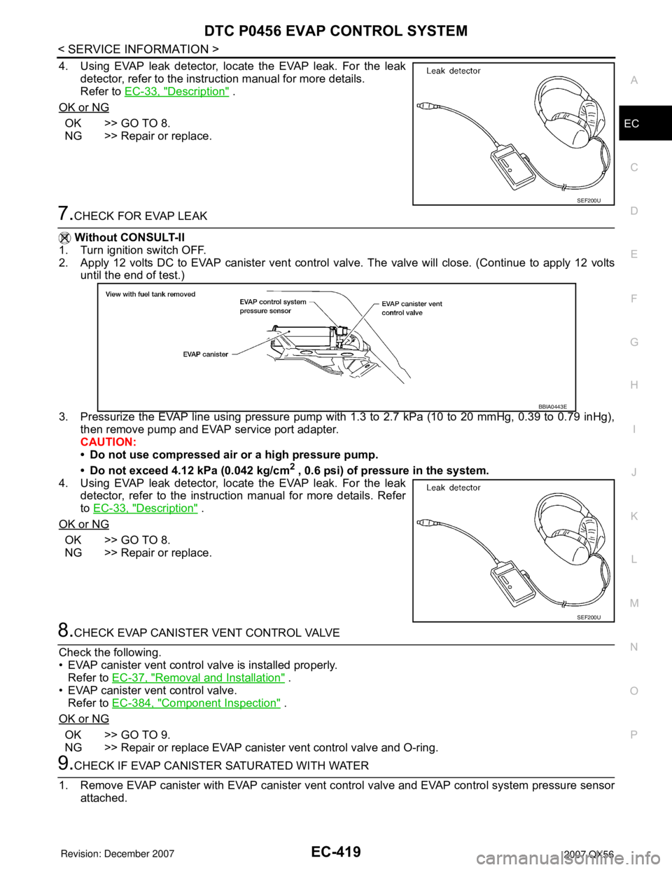
4. Using EVAP leak detector, locate the EVAP leak. For the leak
detector, refer to the instruction manual for more details.
Refer to EC-33, "
Description" .
OK or NG
OK >> GO TO 8.
NG >> Repair or replace.
7.CHECK FOR EVAP LEAK
Without CONSULT-II
1. Turn ignition switch OFF.
2. Apply 12 volts DC to EVAP canister vent control valve. The valve will close. (Continue to apply 12 volts
until the end of test.)
3. Pressurize the EVAP line using pressure pump with 1.3 to 2.7 kPa (10 to 20 mmHg, 0.39 to 0.79 inHg),
then remove pump and EVAP service port adapter.
CAUTION:
• Do not use compressed air or a high pressure pump.
• Do not exceed 4.12 kPa (0.042 kg/cm
2 , 0.6 psi) of pressure in the system.
4. Using EVAP leak detector, locate the EVAP leak. For the leak
detector, refer to the instruction manual for more details. Refer
to EC-33, "
Description" .
OK or NG
OK >> GO TO 8.
NG >> Repair or replace.
8.CHECK EVAP CANISTER VENT CONTROL VALVE
Check the following.
• EVAP canister vent control valve is installed properly.
Refer to EC-37, "
Removal and Installation" .
• EVAP canister vent control valve.
Refer to EC-384, "
Component Inspection" .
OK or NG
OK >> GO TO 9.
NG >> Repair or replace EVAP canister vent control valve and O-ring.
9.CHECK IF EVAP CANISTER SATURATED WITH WATER
1. Remove EVAP canister with EVAP canister vent control valve and EVAP control system pressure sensor
attached.
SEF200U
BBIA0443E
SEF200U
Page 1553 of 3061

EC-470
< SERVICE INFORMATION >
DTC P1217 ENGINE OVER TEMPERATURE
On Board Diagnosis Logic
INFOID:0000000003531991
If the cooling fan or another component in the cooling system malfunctions, engine coolant temperature will
rise.
When the engine coolant temperature reaches an abnormally high temperature condition, a malfunction is
indicated.
This self-diagnosis has the one trip detection logic.
CAUTION:
When a malfunction is indicated, be sure to replace the coolant. Refer to CO-9, "
Changing Engine
Coolant". Also, replace the engine oil. Refer to LU-9, "Changing Engine Oil".
1. Fill radiator with coolant up to specified level with a filling speed of 2 liters per minute. Be sure to
use coolant with the proper mixture ratio. Refer to MA-10, "
SAE Viscosity Number".
2. After refilling coolant, run engine to ensure that no water-flow noise is emitted.
Overall Function CheckINFOID:0000000003531992
Use this procedure to check the overall function of the cooling fan. During this check, a DTC might not be con-
firmed.
WARNING:
Never remove the radiator cap and/or reservoir tank cap when the engine is hot. Serious burns could
be caused by high pressure fluid escaping from the radiator and/or reservoir tank.
Wrap a thick cloth around cap. Carefully remove the cap by turning it a quarter turn to allow built-up
pressure to escape. Then turn the cap all the way off.
WITH CONSULT-II
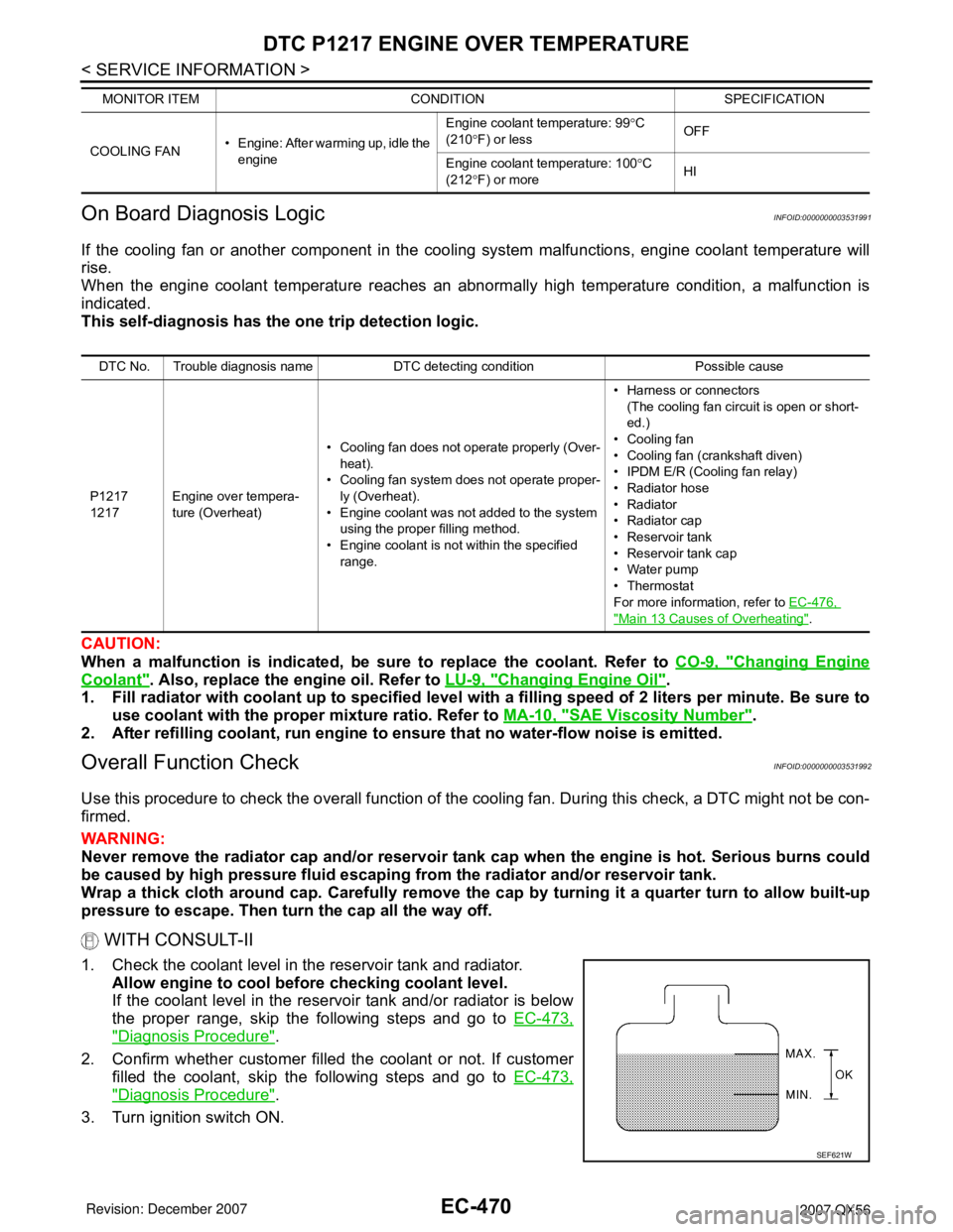
1. Check the coolant level in the reservoir tank and radiator.
Allow engine to cool before checking coolant level.
If the coolant level in the reservoir tank and/or radiator is below
the proper range, skip the following steps and go to EC-473,
"Diagnosis Procedure".
2. Confirm whether customer filled the coolant or not. If customer
filled the coolant, skip the following steps and go to EC-473,
"Diagnosis Procedure".
3. Turn ignition switch ON.
COOLING FAN• Engine: After warming up, idle the
engineEngine coolant temperature: 99°C
(210°F) or lessOFF
Engine coolant temperature: 100°C
(212°F) or moreHI MONITOR ITEM CONDITION SPECIFICATION
DTC No. Trouble diagnosis name DTC detecting condition Possible cause
P1217
1217Engine over tempera-
ture (Overheat)• Cooling fan does not operate properly (Over-
heat).
• Cooling fan system does not operate proper-
ly (Overheat).
• Engine coolant was not added to the system
using the proper filling method.
• Engine coolant is not within the specified
range.• Harness or connectors
(The cooling fan circuit is open or short-
ed.)
• Cooling fan
• Cooling fan (crankshaft diven)
• IPDM E/R (Cooling fan relay)
•Radiator hose
•Radiator
•Radiator cap
• Reservoir tank
• Reservoir tank cap
• Water pump
•Thermostat
For more information, refer to EC-476,
"Main 13 Causes of Overheating".
SEF621W
Page 1557 of 3061

EC-474
< SERVICE INFORMATION >
DTC P1217 ENGINE OVER TEMPERATURE
OK (Without CONSULT-II)>>GO TO 3.
NG >> Check cooling fan (crankshaft driven). Refer to CO-16, "
Removal and Installation (Crankshaft
Driven Type)".
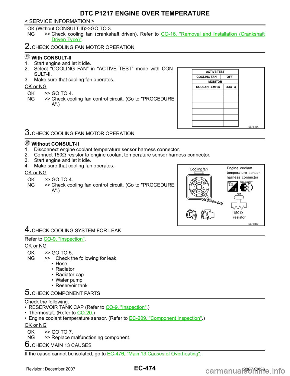
2.CHECK COOLING FAN MOTOR OPERATION
With CONSULT-II
1. Start engine and let it idle.
2. Select “COOLING FAN” in “ACTIVE TEST” mode with CON-
SULT-II.
3. Make sure that cooling fan operates.
OK or NG
OK >> GO TO 4.
NG >> Check cooling fan control circuit. (Go to "PROCEDURE
A".)
3.CHECK COOLING FAN MOTOR OPERATION
Without CONSULT-II
1. Disconnect engine coolant temperature sensor harness connector.
2. Connect 150Ω resistor to engine coolant temperature sensor harness connector.
3. Start engine and let it idle.
4. Make sure that cooling fan operates.
OK or NG
OK >> GO TO 4.
NG >> Check cooling fan control circuit. (Go to "PROCEDURE
A".)
4.CHECK COOLING SYSTEM FOR LEAK
Refer to CO-9, "
Inspection".
OK or NG
OK >> GO TO 5.
NG >> Check the following for leak.
•Hose
• Radiator
• Radiator cap
• Water pump
• Reservoir tank
5.CHECK COMPONENT PARTS
Check the following.
• RESERVOIR TANK CAP (Refer to CO-9, "
Inspection".)
• Thermostat. (Refer to CO-20
.)
• Engine coolant temperature sensor. (Refer to EC-209, "
Component Inspection".)
OK or NG
OK >> GO TO 7.
NG >> Replace malfunctioning component.
6.CHECK MAIN 13 CAUSES
If the cause cannot be isolated, go to EC-476, "
Main 13 Causes of Overheating".
SEF646X
SEF882V
Page 1780 of 3061
EM-10
< SERVICE INFORMATION >
NOISE, VIBRATION AND HARSHNESS (NVH) TROUBLESHOOTING
NOISE, VIBRATION AND HARSHNESS (NVH) TROUBLESHOOTING
NVH Troubleshooting - Engine NoiseINFOID:0000000003586490
AWBIA0149ZZ
1. Timing chain 2. Intake valve 3. Exhaust valve
4. Drive belt 5. Water pump A. VTC noise
Page 1781 of 3061

NOISE, VIBRATION AND HARSHNESS (NVH) TROUBLESHOOTINGEM-11
< SERVICE INFORMATION >
C
DE
F
G H
I
J
K L
M A
EM
NP
O
Use the Chart Below to Help You
Find the Cause of the SymptomINFOID:0000000003531519
1. Locate the area where noise occurs.
2. Confirm the type of noise.
3. Specify the operating condition of engine.
4. Check specified noise source.
If necessary, repair or replace these parts.
A: Closely related B: Related C: Sometimes related —: Not relatedB. Tappet noise C. Camshaft bearing noise D. Valve mechanism
E. Rotation mechanism F. Piston pin noise G. Piston slap noise
H. Main bearing noise I. Connecting rod bearing noise J. Drive belt noise (slipping)
K. Drive belt noise (stick/slipping) L. Water pump noise M. Timing chain and chain tensioner noise
Location of noise Ty p e o f
noise Operating condition of engine
Source of noise Check item
Refer-
ence page
Be-
fore
warm- up After
warm-
up When
start-
ing When
idling When
racing While
driv-
ing
Top of en-
gine
Rocker cov-
er
Cylinder
head Ticking or
clicking
C A — A B — Tappet noise Valve clearance
EM-56
Rattle C A — A B CCamshaft
bearing noiseCamshaft journal clear-
ance
Camshaft runout EM-46EM-46
Crankshaft
pulley
Cylinder
block (Side
of engine)
Oil panSlap or
knock
—A—B B— Piston pin
noisePiston and piston pin
clearance
Connecting rod bushing
clearance EM-93
EM-93
Slap or
rap
A——B B A Piston slap
noisePiston-to-bore clear-
ance
Piston ring side clear-
ance
Piston ring end gap
Connecting rod bend
and torsion EM-93EM-93
EM-93
EM-93
Knock A B C B B B
Connecting
rod bearing
noiseConnecting rod bushing
oil clearance (Small
end)
Connecting rod bearing
clearance (Big end)
EM-93EM-93
Knock A B — A B C
Main bearing
noiseMain bearing oil clear-
ance
Crankshaft runout EM-93EM-93
Front of en-
gine
Chain case
cover
Front coverTapping
or ticking
AA—BBB Timing chain
and chain
tensioner
noiseTiming chain cracks
and wear
Timing chain tensioner
operation
EM-38
EM-38
Front of en-
gineSqueak-
ing or
fizzing
AB—B—C
Drive belts
(Sticking or
slipping)Drive belts deflection
EM-13Creaking A B A B A B Drive belts
(Slipping)Idler pulley bearing op-
eration
Squall
Creaking AB—BAB Water pump
noiseWater pump operation
EM-38
Rattle — — A — — — VTC VTC lockpin clearance EM-55