2007 INFINITI QX56 water pump
[x] Cancel search: water pumpPage 1783 of 3061
DRIVE BELTSEM-13
< SERVICE INFORMATION >
C
DE
F
G H
I
J
K L
M A
EM
NP
O
DRIVE BELTS
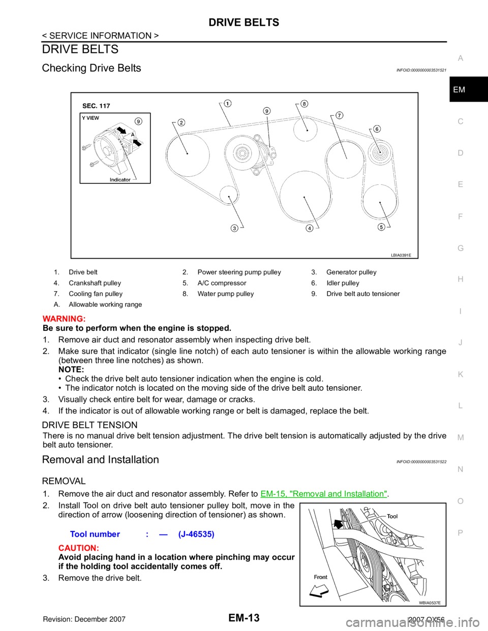
Checking Drive BeltsINFOID:0000000003531521
WARNING:
Be sure to perform when the engine is stopped.
1. Remove air duct and resonator assembly when inspecting drive belt.
2. Make sure that indicator (single line notch) of eac
h auto tensioner is within the allowable working range
(between three line notches) as shown.
NOTE:
• Check the drive belt auto tensioner indication when the engine is cold.
• The indicator notch is located on the moving side of the drive belt auto tensioner.
3. Visually check entire belt for wear, damage or cracks.
4. If the indicator is out of allowable work ing range or belt is damaged, replace the belt.
DRIVE BELT TENSION
There is no manual drive belt tension adjustment. The driv e belt tension is automatically adjusted by the drive
belt auto tensioner.
Removal and InstallationINFOID:0000000003531522
REMOVAL
1. Remove the air duct and resonator assembly. Refer to EM-15, "Removal and Installation".
2. Install Tool on drive belt auto tensioner pulley bolt, move in the direction of arrow (loosening direction of tensioner) as shown.
CAUTION:
Avoid placing hand in a locat ion where pinching may occur
if the holding tool accidentally comes off.
3. Remove the drive belt.
1. Drive belt 2. Power steering pump pulley 3. Generator pulley
4. Crankshaft pulley 5. A/C compressor 6. Idler pulley
7. Cooling fan pulley 8. Water pump pulley 9. Drive belt auto tensioner
A. Allowable working range
LBIA0391E
Tool number : — (J-46535)
WBIA0537E
Page 1808 of 3061
EM-38
< SERVICE INFORMATION >
TIMING CHAIN
Removal and Installation
INFOID:0000000003531533
NOTE:
• To remove timing chain and associated parts, start with those on the LH bank. The procedure for removing parts on the RH bank is omitted because it is the same as that for removal on the LH bank.
• To install timing chain and associated parts, start with those on the RH bank. The procedure for installing parts on the LH bank is omitted because it is t he same as that for installation on the RH bank.
REMOVAL
1. Remove the engine assembly from the vehicle. Refer to EM-74, "Removal and Installation".
2. Remove the following components and related parts: • Drive belt auto tensioner and idler pulley. Refer to EM-13, "
Removal and Installation".
• Thermostat housing and water hose. Refer to CO-20, "
Removal and Installation".
• Power steering oil pump bracket. Refer to LU-14, "
Removal and Installation".
• Oil pan (lower), (upper) and oil strainer. Refer to EM-24, "
Removal and Installation".
• Ignition coil. Refer to EM-28, "
Removal and Installation".
• Rocker cover. Refer to EM-35, "
Removal and Installation".
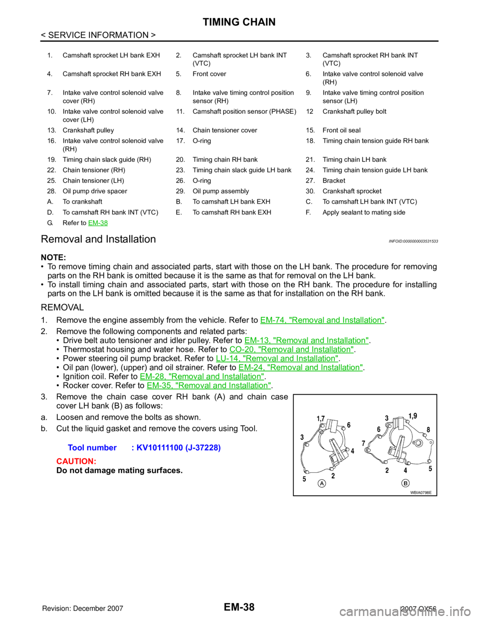
3. Remove the chain case cover RH bank (A) and chain case cover LH bank (B) as follows:
a. Loosen and remove the bolts as shown.
b. Cut the liquid gasket and remove the covers using Tool.
CAUTION:
Do not damage mating surfaces.
1. Camshaft sprocket LH bank EXH 2. Camshaft sprocket LH bank INT (VTC)3. Camshaft sprocket RH bank INT
(VTC)
4. Camshaft sprocket RH bank EXH 5. Front cover 6. Intake valve control solenoid valve (RH)
7. Intake valve control solenoid valve cover (RH) 8. Intake valve timing control position
sensor (RH) 9. Intake valve timing control position
sensor (LH)
10. Intake valve control solenoid valve cover (LH) 11. Camshaft position sensor (PHASE) 12 Crankshaft pulley bolt
13. Crankshaft pulley 14. Chain tensioner cover 15. Front oil seal
16. Intake valve control solenoid valve (RH) 17. O-ring 18. Timing chain tension guide RH bank
19. Timing chain slack guide (RH) 20. Timing chain RH bank 21. Timing chain LH bank
22. Chain tensioner (RH) 23. Timing chain slack guide LH bank 24. Timing chain tension guide LH bank
25. Chain tensioner (LH) 26. O-ring 27. Bracket
28. Oil pump drive spacer 29. Oil pump assembly 30. Crankshaft sprocket
A. To crankshaft B. To camshaft LH bank EXH C. To camshaft LH bank INT (VTC)
D. To camshaft RH bank INT (VTC) E. To camshaft RH bank EXH F. Apply sealant to mating side
G. Refer to EM-38
Tool number : KV10111100 (J-37228)
WBIA0798E
Page 2112 of 3061
IDX-8
ALPHABETICAL INDEX
Three way catalyst ............................................ EM-21
Three way catalyst function (Bank 1) ............... EC-376
Three way catalyst function (Bank 2) ............... EC-376
Three way catalyst precautions ............................ GI-5
Throttle control motor ....................................... EC-601
Throttle control motor relay .............................. EC-589
Throttle position sensor (TPS) .. EC-224, EC-343, EC-
514, EC-516, EC-621
Throttle valve closed position learning ............... EC-80
Tie-rod ............................................................... PS-15
Timing chain ..................................................... EM-37
Tire rotation ....................................................... MA-28
Tire size .............................................................. GI-51
Torque converter installation AT-239, AT-240, AT-243,
AT-244
Torque convertor clutch solenoid valve ... AT-114, AT-
116
Tow truck towing ................................................. GI-44
Towing point ....................................................... GI-45
TPS1 - Wiring diagram .................................... EC-345
TPS2 - Wiring diagram .................................... EC-226
TPS3 - Wiring diagram .................................... EC-623
Traction control system - Wiring diagram ....... BRC-16
Transfer control device ............. TF-75, TF-79, TF-138
Transfer control unit inspection table ................. TF-35
Transfer dropping resistor .................................. TF-89
Transfer fluid temperature sensor TF-103, TF-154, TF-
167
Transfer motor .................................... TF-101, TF-142
Transfer motor relay ........................................ TF-101
Transfer oil replacement ................................... MA-24
Transfer serial number ........................................ GI-50
Transmission serial number ................................ GI-50
Tread-FR&RR (Dimensions) ............................... GI-51
Trim ..................................................................... EI-35
TRNSCV - Wiring diagram .................. BL-130, BL-146
Trouble diagnoses .............................................. GI-11
Turbine revolution sensor ................................ AT-105
TURN - Wiring diagram ...................................... LT-67
Turn signal lamp ................................................. LT-63
Two trip detection logic ...................................... EC-49
Two-pole lift ........................................................ GI-43
V
Vacuum hose (brake system) ............................ BR-20
Vacuum hose drawing (Engine control) ........... EC-106
Valve clearance ................................................ EM-55
Valve guide ....................................................... EM-69
Vanity mirror lamp ............................................. LT-110
VDC (vehicle dynamics control) ........................ BRC-7
VDC -Wiring diagram ...................................... BRC-16
Vehicle identification number .............................. GI-49
Vehicle recovery (freeing a stuck vehicle) .......... GI-45
Vehicle security (theft warning) system ............. BL-67
Vehicle speed sensor (VSS) ............................ EC-464
VEHSEC - Wiring diagram ................................. BL-71
VENT/V - Wiring diagram .................. EC-412, EC-419
VIN registration .................................................. EC-79
Viscosity number (SAE) .................................... MA-12
VSS A/T - Wiring diagram .................. AT-107, AT-109
W
W/ANT - Wiring diagram .................................... AV-59
Wait detection switch ......................................... TF-68
WARN - Wiring diagram ...................................... DI-29
Warning chime .................................................... DI-38
Warning lamps .................................................... DI-28
Washer, front ..................................................... WW-4
Washer, rear .................................................... WW-29
Water pump ...................................................... CO-19
Water temperature gauge ..................................... DI-5
Wheel alignment (front) ..................................... FSU-6
Wheel alignment (rear) ................................... RSU-25
Wheel bearing (front) ........................................ FAX-5
Wheel bearing (rear) ......................................... RAX-5
Wheel hub (rear) ............................................... RAX-5
Wheel size .......................................................... GI-51
Wheelbase (Dimensions) .................................... GI-51
Width (Dimensions) ............................................. GI-51
WINDOW - Wiring diagram .............................. GW-22
Window, door ...................................... GW-62, GW-65
Windshield ....................................................... GW-11
WIP/R - Wiring diagram ................................... WW-33
WIPER - Wiring diagram .................................... WW-8
Wiper, front ........................................................ WW-4
Wiper, rear ....................................................... WW-29
Wiring Diagram (Cell code) list ......................... PG-62
Wiring diagrams .................................................. GI-15
WT-T/WARN - Wiring diagram .......................... WT-11
Page 2374 of 3061
MA-12
< SERVICE INFORMATION >
ENGINE MAINTENANCE
ENGINE MAINTENANCE
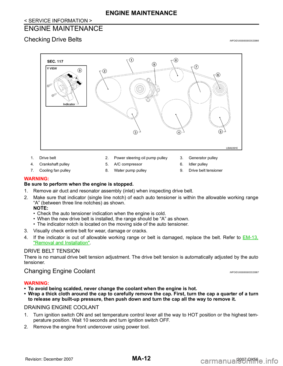
Checking Drive BeltsINFOID:0000000003533866
WARNING:
Be sure to perform when the engine is stopped.
1. Remove air duct and resonator assembly (inlet) when inspecting drive belt.
2. Make sure that indicator (single line notch) of each auto tensioner is within the allowable working range
“A” (between three line notches) as shown.
NOTE:
• Check the auto tensioner indication when the engine is cold.
• When the new drive belt is installed, the range should be “A” as shown.
• The indicator notch is located on the moving side of the auto tensioner.
3. Visually check entire belt for wear, damage or cracks.
4. If the indicator is out of allowable working range or belt is damaged, replace the belt. Refer to EM-13,
"Removal and Installation".
DRIVE BELT TENSION
There is no manual drive belt tension adjustment. The drive belt tension is automatically adjusted by the auto
tensioner.
Changing Engine CoolantINFOID:0000000003533867
WARNING:
• To avoid being scalded, never change the coolant when the engine is hot.
• Wrap a thick cloth around the cap to carefully remove the cap. First, turn the cap a quarter of a turn
to release any built-up pressure, then push down and turn the cap all the way to remove it.
DRAINING ENGINE COOLANT
1. Turn ignition switch ON and set temperature control lever all the way to HOT position or the highest tem-
perature position. Wait 10 seconds and turn ignition switch OFF.
2. Remove the engine front undercover using power tool.
1. Drive belt 2. Power steering oil pump pulley 3. Generator pulley
4. Crankshaft pulley 5. A/C compressor 6. Idler pulley
7. Cooling fan pulley 8. Water pump pulley 9. Drive belt tensioner
LBIA0391E
Page 2377 of 3061
ENGINE MAINTENANCE
MA-15
< SERVICE INFORMATION >
C
D
E
F
G
H
I
J
K
MA
B
MA
N
O
P
2. Fill the radiator and the reservoir tank (to the “MAX” line), with water. Reinstall the radiator cap and leave
the vented reservoir cap off.
3. Run the engine until it reaches normal operating temperature.
4. Press the engine accelerator two or three times under no-load.
5. Stop the engine and wait until it cools down.
6. Drain the water from the engine cooling system. Refer to CO-9, "
Changing Engine Coolant" .
7. Repeat steps 2 through 6 until clear water begins to drain from the radiator.
Checking Fuel LineINFOID:0000000003533868
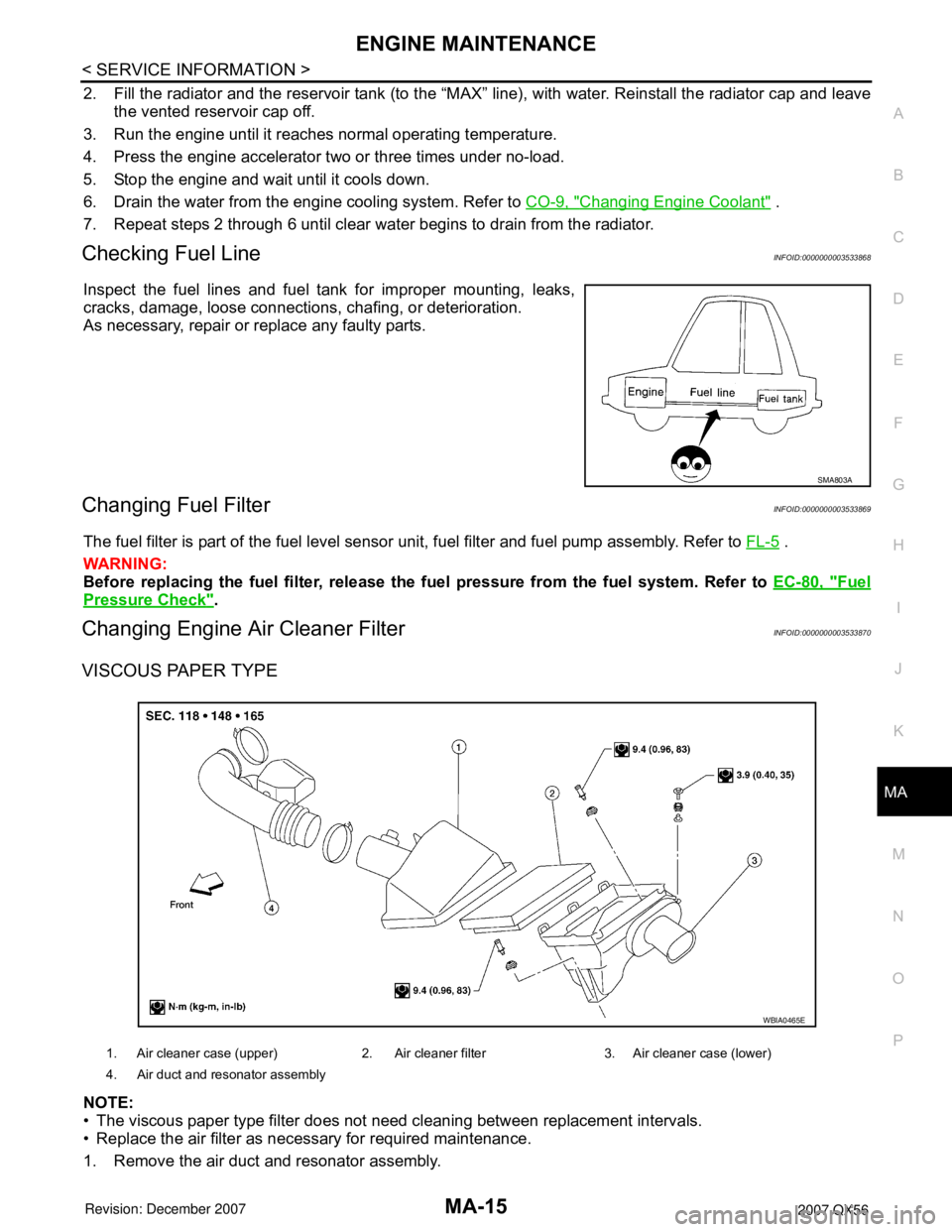
Inspect the fuel lines and fuel tank for improper mounting, leaks,
cracks, damage, loose connections, chafing, or deterioration.
As necessary, repair or replace any faulty parts.
Changing Fuel FilterINFOID:0000000003533869
The fuel filter is part of the fuel level sensor unit, fuel filter and fuel pump assembly. Refer to FL-5 .
WARNING:
Before replacing the fuel filter, release the fuel pressure from the fuel system. Refer to EC-80, "
Fuel
Pressure Check".
Changing Engine Air Cleaner FilterINFOID:0000000003533870
VISCOUS PAPER TYPE
NOTE:
• The viscous paper type filter does not need cleaning between replacement intervals.
• Replace the air filter as necessary for required maintenance.
1. Remove the air duct and resonator assembly.
SMA803A
1. Air cleaner case (upper) 2. Air cleaner filter 3. Air cleaner case (lower)
4. Air duct and resonator assembly
WBIA0465E