2007 INFINITI QX56 radiator cap
[x] Cancel search: radiator capPage 1000 of 3061

ENGINE COOLANT
CO-11
< SERVICE INFORMATION >
C
D
E
F
G
H
I
J
K
L
MA
CO
N
P O
3. Remove the vented reservoir cap and replace it with a non-vented reservoir cap before filling the cooling
system.
4. Install the Tool by installing the radiator cap adapter onto the
radiator neck opening. Then attach the gauge body assembly
with the refill tube and the venturi assembly to the radiator cap
adapter.
5. Insert the refill hose into the coolant mixture container that is
placed at floor level. Make sure the ball valve is in the closed
position.
• Use recommended NISSAN Long Life Anti-freeze coolant or
equivalent. Refer to MA-10, "
SAE Viscosity Number".
6. Install an air hose to the venturi assembly, the air pressure must
be within specification.
CAUTION:
The compressed air supply must be equipped with an air
dryer.
7. The vacuum gauge will begin to rise and there will be an audible hissing noise. During this process open
the ball valve on the refill hose slightly. Coolant will be visible rising in the refill hose. Once the refill hose is
full of coolant, close the ball valve. This will purge any air trapped in the refill hose.
8. Continue to draw the vacuum until the gauge reaches 28 inches
of vacuum. The gauge may not reach 28 inches in high altitude
locations, refer to the vacuum specifications based on the alti-
tude above sea level.
9. When the vacuum gauge has reached the specified amount, disconnect the air hose and wait 20 seconds
to see if the system loses any vacuum. If the vacuum level drops, perform any necessary repairs to the
system and repeat steps 6 - 8 to bring the vacuum to the specified amount. Recheck for any leaks.
10. Place the coolant container (with the refill hose inserted) at the same level as the top of the radiator. Then
open the ball valve on the refill hose so the coolant will be drawn up to fill the cooling system. The cooling
system is full when the vacuum gauge reads zero.
CAUTION:
Do not allow the coolant container to get too low when filling, to avoid air from being drawn into
the cooling system.
11. Remove the Tool from the radiator neck opening and install the radiator cap.
12. Remove the non-vented reservoir cap.
13. Fill the cooling system reservoir tank to the specified level. Run the engine to warm up the cooling system
and top up the system as necessary before installing the vented reservoir cap.
FLUSHING COOLING SYSTEM
Tool number : KV991J0070 (J-45695)
Cooling system capacity
(with reservoir): Refer to MA-10, "
Fluids
and Lubricants".
Compressed air
supply pressure: 5.7 - 8.5 kPa (5.6 - 8.4 kg/cm
2,
80 - 120 psi)
LLIA0058E
Altitude above sea level Vacuum gauge reading
0 - 100 m (328 ft) : 28 inches of vacuum
300 m (984 ft) : 27 inches of vacuum
500 m (1,641 ft) : 26 inches of vacuum
1,000 m (3,281 ft) : 24 - 25 inches of vacuum
LLIA0057E
Page 1001 of 3061

CO-12
< SERVICE INFORMATION >
ENGINE COOLANT
1. Drain the water from the engine cooling system.
2. Fill the radiator and the reservoir tank (to the “MAX” line), with water. Reinstall the radiator cap and leave
the vented reservoir cap off.
3. Run the engine until it reaches normal operating temperature.
4. Press the engine accelerator two or three times under no-load.
5. Stop the engine and wait until it cools down.
6. Drain the water from the engine cooling system.
7. Repeat steps 2 through 6 until clear water begins to drain from the radiator.
Page 1002 of 3061
RADIATOR
CO-13
< SERVICE INFORMATION >
C
D
E
F
G
H
I
J
K
L
MA
CO
N
P O
RADIATOR
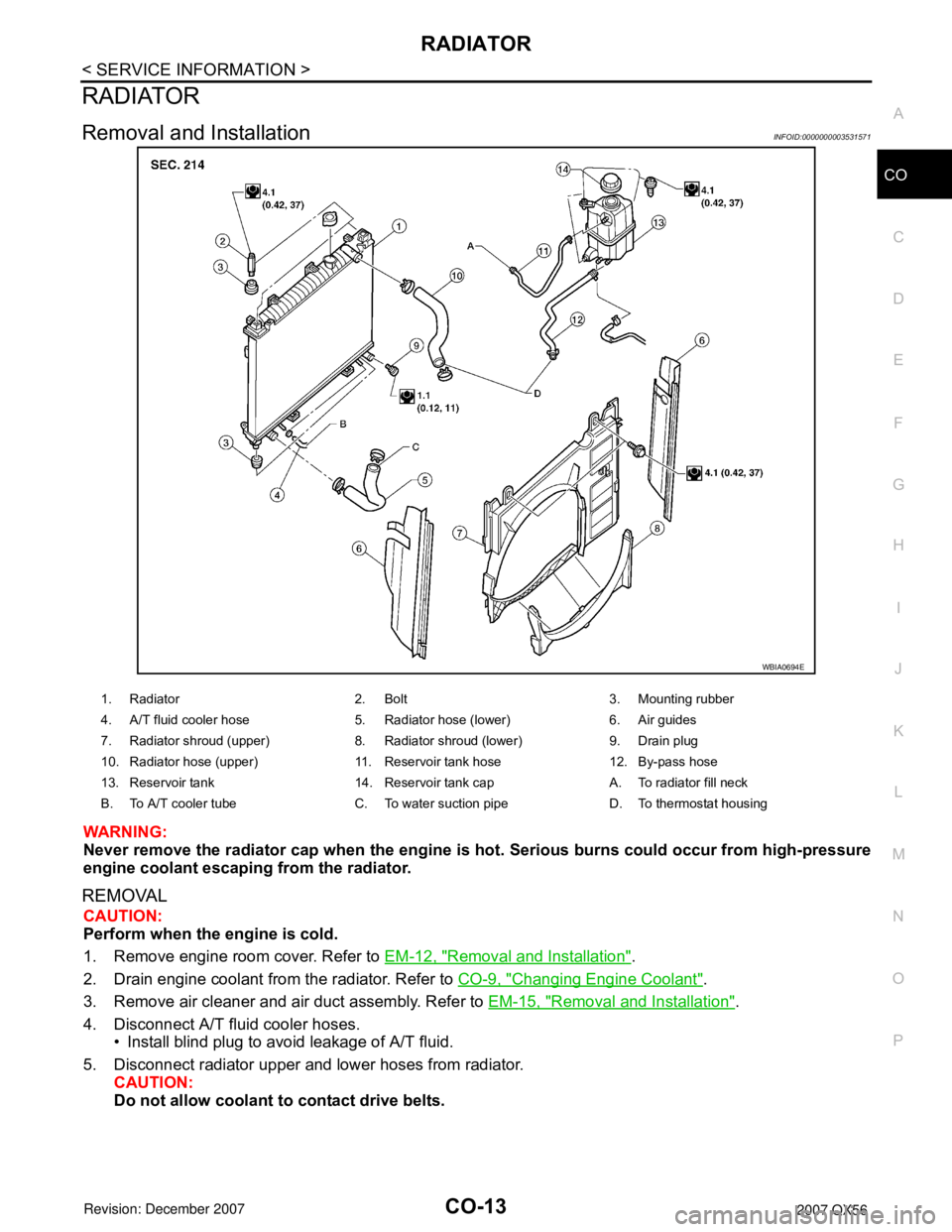
Removal and InstallationINFOID:0000000003531571
WARNING:
Never remove the radiator cap when the engine is hot. Serious burns could occur from high-pressure
engine coolant escaping from the radiator.
REMOVAL
CAUTION:
Perform when the engine is cold.
1. Remove engine room cover. Refer to EM-12, "
Removal and Installation".
2. Drain engine coolant from the radiator. Refer to CO-9, "
Changing Engine Coolant".
3. Remove air cleaner and air duct assembly. Refer to EM-15, "
Removal and Installation".
4. Disconnect A/T fluid cooler hoses.
• Install blind plug to avoid leakage of A/T fluid.
5. Disconnect radiator upper and lower hoses from radiator.
CAUTION:
Do not allow coolant to contact drive belts.
WBIA0694E
1. Radiator 2. Bolt 3. Mounting rubber
4. A/T fluid cooler hose 5. Radiator hose (lower) 6. Air guides
7. Radiator shroud (upper) 8. Radiator shroud (lower) 9. Drain plug
10. Radiator hose (upper) 11. Reservoir tank hose 12. By-pass hose
13. Reservoir tank 14. Reservoir tank cap A. To radiator fill neck
B. To A/T cooler tube C. To water suction pipe D. To thermostat housing
Page 1011 of 3061

CO-22
< SERVICE INFORMATION >
SERVICE DATA AND SPECIFICATIONS (SDS)
SERVICE DATA AND SPECIFICATIONS (SDS)
Standard and LimitINFOID:0000000003531577
ENGINE COOLANT CAPACITY (APPROXIMATE)
Unit: (US gal, Imp gal)
THERMOSTAT
RADIATOR
Unit: kPa (kg/cm2, psi)
Engine coolant capacity with reservoir tank ("MAX" level) 14.4 (3 3/4, 3 1/8)
Valve opening temperature 80 - 84°C (176 - 183°F)
Maximum valve lift More than 10 mm/95°C (0.39 in/203°F)
Valve closing temperature 77°C (171°F) or higher
Reservoir cap relief pressure Standard 95 - 125 (0.97- 1.28, 14 - 18)
Leakage test pressure 137 (1.4, 20)
Page 1104 of 3061
PREPARATION
EC-21
< SERVICE INFORMATION >
C
D
E
F
G
H
I
J
K
L
MA
EC
N
P O
PREPARATION
Special Service ToolINFOID:0000000003531583
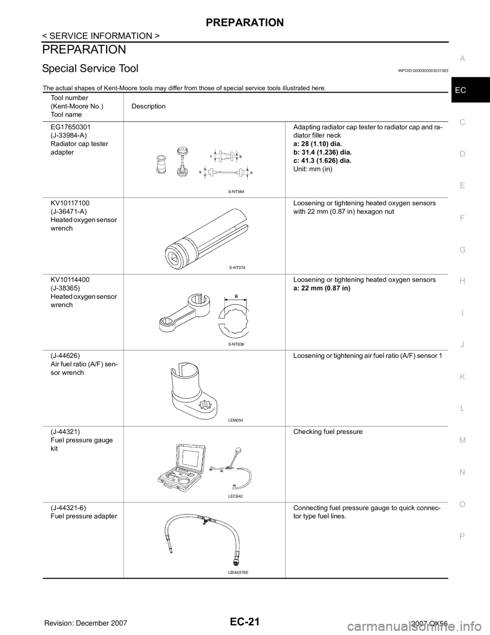
The actual shapes of Kent-Moore tools may differ from those of special service tools illustrated here.
Tool number
(Kent-Moore No.)
Tool nameDescription
EG17650301
(J-33984-A)
Radiator cap tester
adapterAdapting radiator cap tester to radiator cap and ra-
diator filler neck
a: 28 (1.10) dia.
b: 31.4 (1.236) dia.
c: 41.3 (1.626) dia.
Unit: mm (in)
KV10117100
(J-36471-A)
Heated oxygen sensor
wrenchLoosening or tightening heated oxygen sensors
with 22 mm (0.87 in) hexagon nut
KV10114400
(J-38365)
Heated oxygen sensor
wrenchLoosening or tightening heated oxygen sensors
a: 22 mm (0.87 in)
(J-44626)
Air fuel ratio (A/F) sen-
sor wrenchLoosening or tightening air fuel ratio (A/F) sensor 1
(J-44321)
Fuel pressure gauge
kitChecking fuel pressure
(J-44321-6)
Fuel pressure adapterConnecting fuel pressure gauge to quick connec-
tor type fuel lines.
S-NT564
S-NT379
S-NT636
LEM054
LEC642
LBIA0376E
Page 1176 of 3061
TROUBLE DIAGNOSIS
EC-93
< SERVICE INFORMATION >
C
D
E
F
G
H
I
J
K
L
MA
EC
N
P O
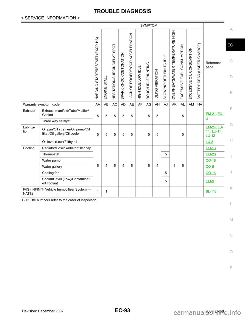
1 - 6: The numbers refer to the order of inspection.Exhaust Exhaust manifold/Tube/Muffler/
Gasket
55555 55 5EM-21
, EX-
3Three way catalyst
Lubrica-
tionOil pan/Oil strainer/Oil pump/Oil
filter/Oil gallery/Oil cooler
55555 55 5EM-24
, LU-
14 , LU-11 ,
LU-12
Oil level (Low)/Filthy oilLU-8
Cooling Radiator/Hose/Radiator filler cap
55555 55 45CO-13
Thermostat 5CO-20
Water pumpCO-18
Water galleryCO-8
Cooling fan 5CO-16
Coolant level (Low)/Contaminat-
ed coolant5CO-9
IVIS (INFINITI Vehicle Immobilizer System —
NATS)11BL-116
SYMPTOM
Reference
page
HARD/NO START/RESTART (EXCP. HA)
ENGINE STALL
HESITATION/SURGING/FLAT SPOT
SPARK KNOCK/DETONATION
LACK OF POWER/POOR ACCELERATION
HIGH IDLE/LOW IDLE
ROUGH IDLE/HUNTING
IDLING VIBRATION
SLOW/NO RETURN TO IDLE
OVERHEATS/WATER TEMPERATURE HIGH
EXCESSIVE FUEL CONSUMPTION
EXCESSIVE OIL CONSUMPTION
BATTERY DEAD (UNDER CHARGE)
Warranty symptom code AA AB AC AD AE AF AG AH AJ AK AL AM HA
Page 1553 of 3061
EC-470
< SERVICE INFORMATION >
DTC P1217 ENGINE OVER TEMPERATURE
On Board Diagnosis Logic
INFOID:0000000003531991
If the cooling fan or another component in the cooling system malfunctions, engine coolant temperature will
rise.
When the engine coolant temperature reaches an abnormally high temperature condition, a malfunction is
indicated.
This self-diagnosis has the one trip detection logic.
CAUTION:
When a malfunction is indicated, be sure to replace the coolant. Refer to CO-9, "
Changing Engine
Coolant". Also, replace the engine oil. Refer to LU-9, "Changing Engine Oil".
1. Fill radiator with coolant up to specified level with a filling speed of 2 liters per minute. Be sure to
use coolant with the proper mixture ratio. Refer to MA-10, "
SAE Viscosity Number".
2. After refilling coolant, run engine to ensure that no water-flow noise is emitted.
Overall Function CheckINFOID:0000000003531992
Use this procedure to check the overall function of the cooling fan. During this check, a DTC might not be con-
firmed.
WARNING:
Never remove the radiator cap and/or reservoir tank cap when the engine is hot. Serious burns could
be caused by high pressure fluid escaping from the radiator and/or reservoir tank.
Wrap a thick cloth around cap. Carefully remove the cap by turning it a quarter turn to allow built-up
pressure to escape. Then turn the cap all the way off.
WITH CONSULT-II
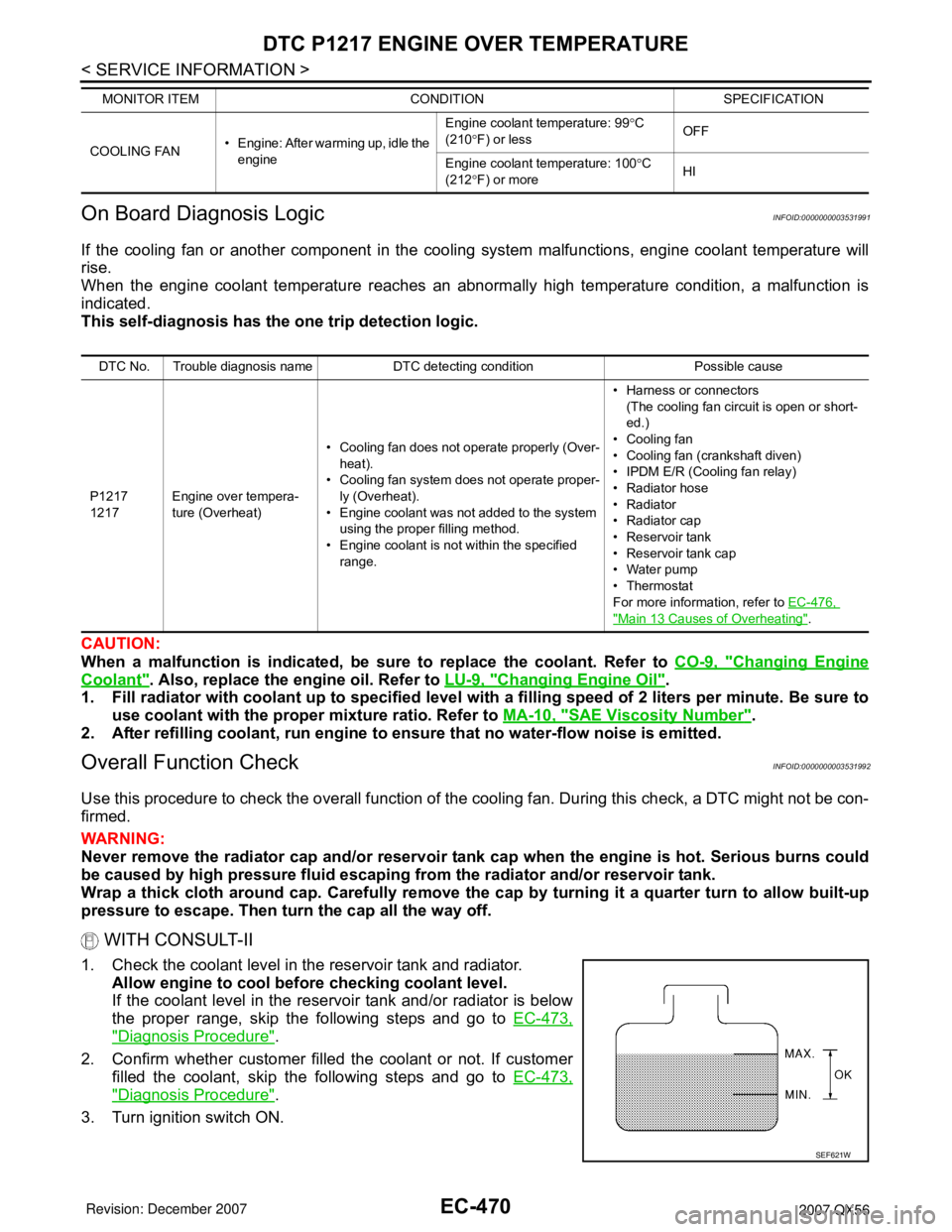
1. Check the coolant level in the reservoir tank and radiator.
Allow engine to cool before checking coolant level.
If the coolant level in the reservoir tank and/or radiator is below
the proper range, skip the following steps and go to EC-473,
"Diagnosis Procedure".
2. Confirm whether customer filled the coolant or not. If customer
filled the coolant, skip the following steps and go to EC-473,
"Diagnosis Procedure".
3. Turn ignition switch ON.
COOLING FAN• Engine: After warming up, idle the
engineEngine coolant temperature: 99°C
(210°F) or lessOFF
Engine coolant temperature: 100°C
(212°F) or moreHI MONITOR ITEM CONDITION SPECIFICATION
DTC No. Trouble diagnosis name DTC detecting condition Possible cause
P1217
1217Engine over tempera-
ture (Overheat)• Cooling fan does not operate properly (Over-
heat).
• Cooling fan system does not operate proper-
ly (Overheat).
• Engine coolant was not added to the system
using the proper filling method.
• Engine coolant is not within the specified
range.• Harness or connectors
(The cooling fan circuit is open or short-
ed.)
• Cooling fan
• Cooling fan (crankshaft diven)
• IPDM E/R (Cooling fan relay)
•Radiator hose
•Radiator
•Radiator cap
• Reservoir tank
• Reservoir tank cap
• Water pump
•Thermostat
For more information, refer to EC-476,
"Main 13 Causes of Overheating".
SEF621W
Page 1557 of 3061
EC-474
< SERVICE INFORMATION >
DTC P1217 ENGINE OVER TEMPERATURE
OK (Without CONSULT-II)>>GO TO 3.
NG >> Check cooling fan (crankshaft driven). Refer to CO-16, "
Removal and Installation (Crankshaft
Driven Type)".
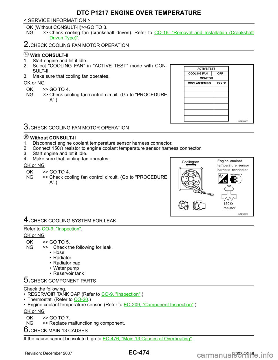
2.CHECK COOLING FAN MOTOR OPERATION
With CONSULT-II
1. Start engine and let it idle.
2. Select “COOLING FAN” in “ACTIVE TEST” mode with CON-
SULT-II.
3. Make sure that cooling fan operates.
OK or NG
OK >> GO TO 4.
NG >> Check cooling fan control circuit. (Go to "PROCEDURE
A".)
3.CHECK COOLING FAN MOTOR OPERATION
Without CONSULT-II
1. Disconnect engine coolant temperature sensor harness connector.
2. Connect 150Ω resistor to engine coolant temperature sensor harness connector.
3. Start engine and let it idle.
4. Make sure that cooling fan operates.
OK or NG
OK >> GO TO 4.
NG >> Check cooling fan control circuit. (Go to "PROCEDURE
A".)
4.CHECK COOLING SYSTEM FOR LEAK
Refer to CO-9, "
Inspection".
OK or NG
OK >> GO TO 5.
NG >> Check the following for leak.
•Hose
• Radiator
• Radiator cap
• Water pump
• Reservoir tank
5.CHECK COMPONENT PARTS
Check the following.
• RESERVOIR TANK CAP (Refer to CO-9, "
Inspection".)
• Thermostat. (Refer to CO-20
.)
• Engine coolant temperature sensor. (Refer to EC-209, "
Component Inspection".)
OK or NG
OK >> GO TO 7.
NG >> Replace malfunctioning component.
6.CHECK MAIN 13 CAUSES
If the cause cannot be isolated, go to EC-476, "
Main 13 Causes of Overheating".
SEF646X
SEF882V