2007 INFINITI QX56 radiator cap
[x] Cancel search: radiator capPage 1559 of 3061
EC-476
< SERVICE INFORMATION >
DTC P1217 ENGINE OVER TEMPERATURE
Main 13 Causes of Overheating
INFOID:0000000003531995
*1: Turn the ignition switch ON.
*2: Engine running at 3,000 rpm for 10 minutes.
*3: Drive at 90 km/h (55 MPH) for 30 minutes and then let idle for 10 minutes.
*4: After 60 minutes of cool down time.
For more information, refer to CO-6
.
Component InspectionINFOID:0000000003531996
COOLING FAN MOTOR
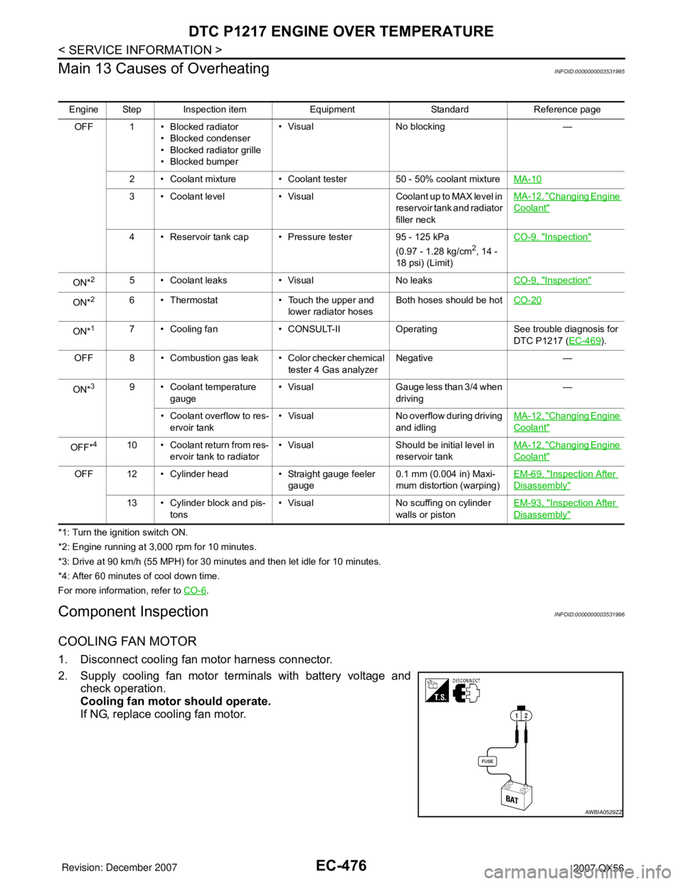
1. Disconnect cooling fan motor harness connector.
2. Supply cooling fan motor terminals with battery voltage and
check operation.
Cooling fan motor should operate.
If NG, replace cooling fan motor.
Engine Step Inspection item Equipment Standard Reference page
OFF 1 • Blocked radiator
• Blocked condenser
• Blocked radiator grille
• Blocked bumper• Visual No blocking —
2 • Coolant mixture • Coolant tester 50 - 50% coolant mixtureMA-10
3 • Coolant level • Visual Coolant up to MAX level in
reservoir tank and radiator
filler neckMA-12, "Changing Engine
Coolant"
4 • Reservoir tank cap • Pressure tester 95 - 125 kPa
(0.97 - 1.28 kg/cm2, 14 -
18 psi) (Limit)CO-9, "
Inspection"
ON*25 • Coolant leaks • Visual No leaksCO-9, "Inspection"
ON*26 • Thermostat • Touch the upper and
lower radiator hosesBoth hoses should be hotCO-20
ON*17 • Cooling fan • CONSULT-II Operating See trouble diagnosis for
DTC P1217 (EC-469
).
OFF 8 • Combustion gas leak • Color checker chemical
tester 4 Gas analyzerNegative —
ON*
39 • Coolant temperature
gauge• Visual Gauge less than 3/4 when
driving—
• Coolant overflow to res-
ervoir tank• Visual No overflow during driving
and idlingMA-12, "
Changing Engine
Coolant"
OFF*410 • Coolant return from res-
ervoir tank to radiator• Visual Should be initial level in
reservoir tankMA-12, "Changing Engine
Coolant"
OFF 12 • Cylinder head • Straight gauge feeler
gauge0.1 mm (0.004 in) Maxi-
mum distortion (warping)EM-69, "Inspection After
Disassembly"
13 • Cylinder block and pis-
tons• Visual No scuffing on cylinder
walls or pistonEM-93, "Inspection After
Disassembly"
AWBIA0529ZZ
Page 1969 of 3061
PRECAUTIONS
GI-3
< SERVICE INFORMATION >
C
D
E
F
G
H
I
J
K
L
MB
GI
N
O
P
General PrecautionINFOID:0000000003531471
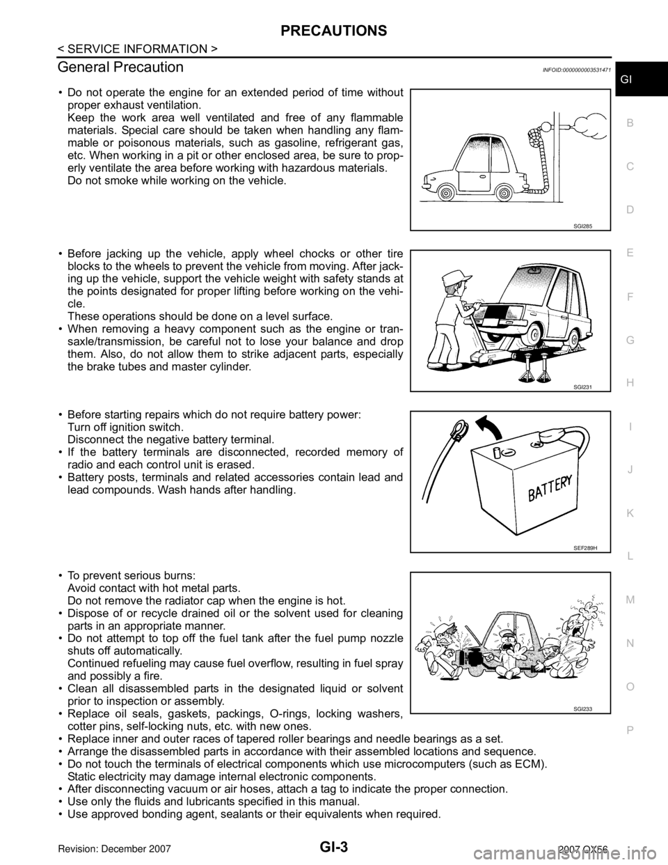
• Do not operate the engine for an extended period of time without
proper exhaust ventilation.
Keep the work area well ventilated and free of any flammable
materials. Special care should be taken when handling any flam-
mable or poisonous materials, such as gasoline, refrigerant gas,
etc. When working in a pit or other enclosed area, be sure to prop-
erly ventilate the area before working with hazardous materials.
Do not smoke while working on the vehicle.
• Before jacking up the vehicle, apply wheel chocks or other tire
blocks to the wheels to prevent the vehicle from moving. After jack-
ing up the vehicle, support the vehicle weight with safety stands at
the points designated for proper lifting before working on the vehi-
cle.
These operations should be done on a level surface.
• When removing a heavy component such as the engine or tran-
saxle/transmission, be careful not to lose your balance and drop
them. Also, do not allow them to strike adjacent parts, especially
the brake tubes and master cylinder.
• Before starting repairs which do not require battery power:
Turn off ignition switch.
Disconnect the negative battery terminal.
• If the battery terminals are disconnected, recorded memory of
radio and each control unit is erased.
• Battery posts, terminals and related accessories contain lead and
lead compounds. Wash hands after handling.
• To prevent serious burns:
Avoid contact with hot metal parts.
Do not remove the radiator cap when the engine is hot.
• Dispose of or recycle drained oil or the solvent used for cleaning
parts in an appropriate manner.
• Do not attempt to top off the fuel tank after the fuel pump nozzle
shuts off automatically.
Continued refueling may cause fuel overflow, resulting in fuel spray
and possibly a fire.
• Clean all disassembled parts in the designated liquid or solvent
prior to inspection or assembly.
• Replace oil seals, gaskets, packings, O-rings, locking washers,
cotter pins, self-locking nuts, etc. with new ones.
• Replace inner and outer races of tapered roller bearings and needle bearings as a set.
• Arrange the disassembled parts in accordance with their assembled locations and sequence.
• Do not touch the terminals of electrical components which use microcomputers (such as ECM).
Static electricity may damage internal electronic components.
• After disconnecting vacuum or air hoses, attach a tag to indicate the proper connection.
• Use only the fluids and lubricants specified in this manual.
• Use approved bonding agent, sealants or their equivalents when required.
SGI285
SGI231
SEF289H
SGI233
Page 2375 of 3061
ENGINE MAINTENANCE
MA-13
< SERVICE INFORMATION >
C
D
E
F
G
H
I
J
K
MA
B
MA
N
O
P
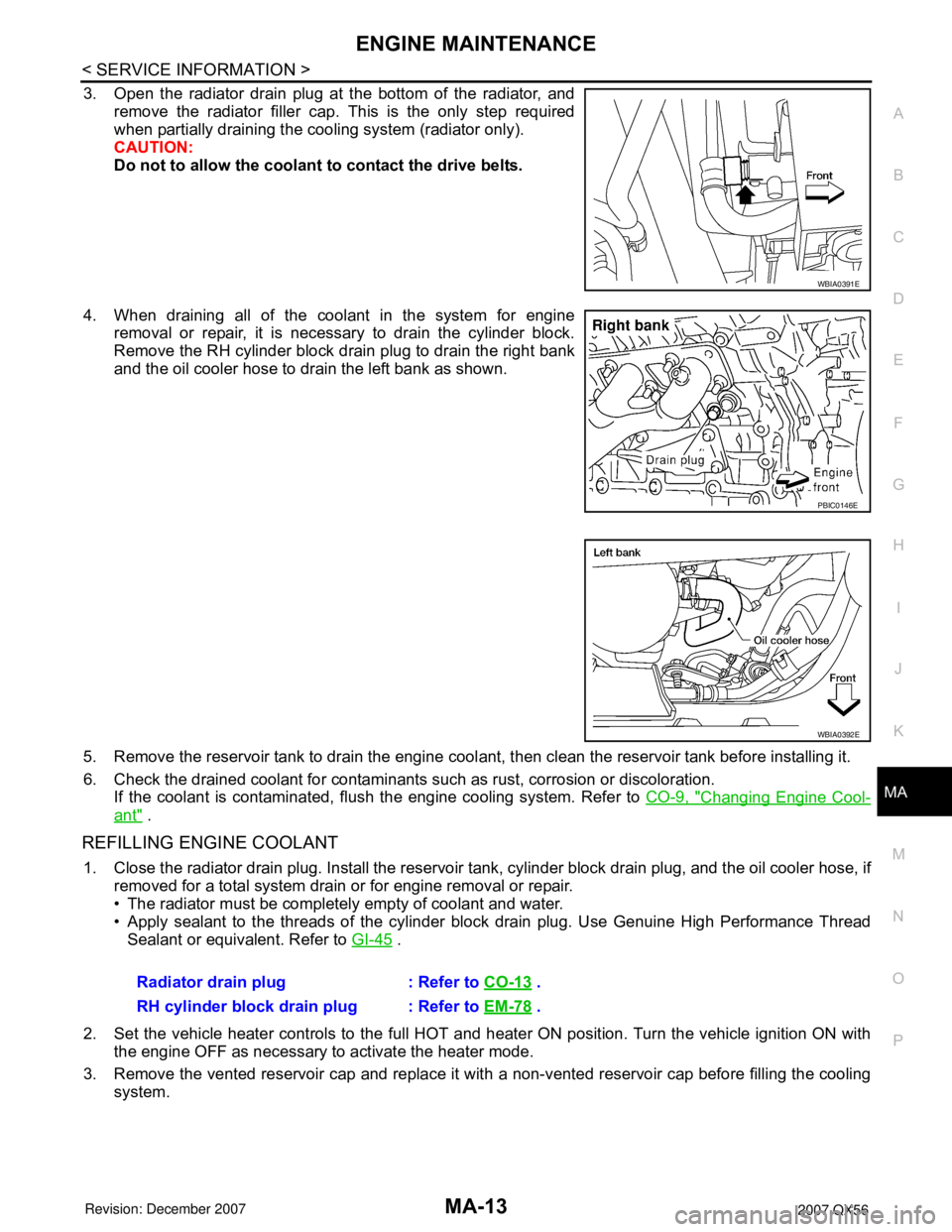
3. Open the radiator drain plug at the bottom of the radiator, and
remove the radiator filler cap. This is the only step required
when partially draining the cooling system (radiator only).
CAUTION:
Do not to allow the coolant to contact the drive belts.
4. When draining all of the coolant in the system for engine
removal or repair, it is necessary to drain the cylinder block.
Remove the RH cylinder block drain plug to drain the right bank
and the oil cooler hose to drain the left bank as shown.
5. Remove the reservoir tank to drain the engine coolant, then clean the reservoir tank before installing it.
6. Check the drained coolant for contaminants such as rust, corrosion or discoloration.
If the coolant is contaminated, flush the engine cooling system. Refer to CO-9, "
Changing Engine Cool-
ant" .
REFILLING ENGINE COOLANT
1. Close the radiator drain plug. Install the reservoir tank, cylinder block drain plug, and the oil cooler hose, if
removed for a total system drain or for engine removal or repair.
• The radiator must be completely empty of coolant and water.
• Apply sealant to the threads of the cylinder block drain plug. Use Genuine High Performance Thread
Sealant or equivalent. Refer to GI-45
.
2. Set the vehicle heater controls to the full HOT and heater ON position. Turn the vehicle ignition ON with
the engine OFF as necessary to activate the heater mode.
3. Remove the vented reservoir cap and replace it with a non-vented reservoir cap before filling the cooling
system.
WBIA0391E
PBIC0146E
WBIA0392E
Radiator drain plug : Refer to CO-13 .
RH cylinder block drain plug : Refer to EM-78
.
Page 2376 of 3061
MA-14
< SERVICE INFORMATION >
ENGINE MAINTENANCE
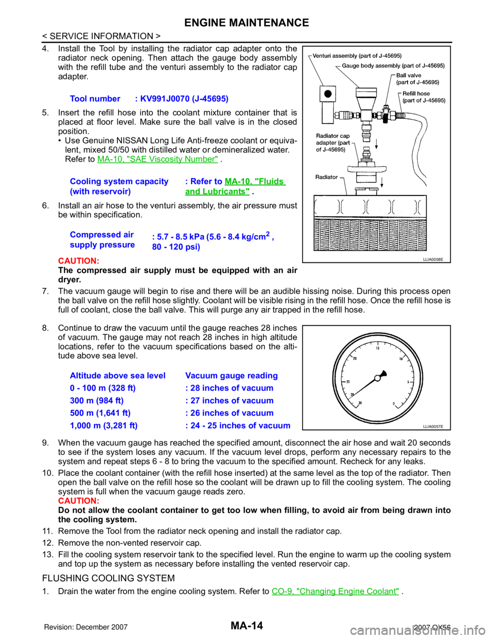
4. Install the Tool by installing the radiator cap adapter onto the
radiator neck opening. Then attach the gauge body assembly
with the refill tube and the venturi assembly to the radiator cap
adapter.
5. Insert the refill hose into the coolant mixture container that is
placed at floor level. Make sure the ball valve is in the closed
position.
• Use Genuine NISSAN Long Life Anti-freeze coolant or equiva-
lent, mixed 50/50 with distilled water or demineralized water.
Refer to MA-10, "
SAE Viscosity Number" .
6. Install an air hose to the venturi assembly, the air pressure must
be within specification.
CAUTION:
The compressed air supply must be equipped with an air
dryer.
7. The vacuum gauge will begin to rise and there will be an audible hissing noise. During this process open
the ball valve on the refill hose slightly. Coolant will be visible rising in the refill hose. Once the refill hose is
full of coolant, close the ball valve. This will purge any air trapped in the refill hose.
8. Continue to draw the vacuum until the gauge reaches 28 inches
of vacuum. The gauge may not reach 28 inches in high altitude
locations, refer to the vacuum specifications based on the alti-
tude above sea level.
9. When the vacuum gauge has reached the specified amount, disconnect the air hose and wait 20 seconds
to see if the system loses any vacuum. If the vacuum level drops, perform any necessary repairs to the
system and repeat steps 6 - 8 to bring the vacuum to the specified amount. Recheck for any leaks.
10. Place the coolant container (with the refill hose inserted) at the same level as the top of the radiator. Then
open the ball valve on the refill hose so the coolant will be drawn up to fill the cooling system. The cooling
system is full when the vacuum gauge reads zero.
CAUTION:
Do not allow the coolant container to get too low when filling, to avoid air from being drawn into
the cooling system.
11. Remove the Tool from the radiator neck opening and install the radiator cap.
12. Remove the non-vented reservoir cap.
13. Fill the cooling system reservoir tank to the specified level. Run the engine to warm up the cooling system
and top up the system as necessary before installing the vented reservoir cap.
FLUSHING COOLING SYSTEM
1. Drain the water from the engine cooling system. Refer to CO-9, "Changing Engine Coolant" . Tool number : KV991J0070 (J-45695)
Cooling system capacity
(with reservoir): Refer to MA-10, "
Fluids
and Lubricants" .
Compressed air
supply pressure: 5.7 - 8.5 kPa (5.6 - 8.4 kg/cm
2 ,
80 - 120 psi)
LLIA0058E
Altitude above sea level Vacuum gauge reading
0 - 100 m (328 ft) : 28 inches of vacuum
300 m (984 ft) : 27 inches of vacuum
500 m (1,641 ft) : 26 inches of vacuum
1,000 m (3,281 ft) : 24 - 25 inches of vacuum
LLIA0057E
Page 2377 of 3061
ENGINE MAINTENANCE
MA-15
< SERVICE INFORMATION >
C
D
E
F
G
H
I
J
K
MA
B
MA
N
O
P
2. Fill the radiator and the reservoir tank (to the “MAX” line), with water. Reinstall the radiator cap and leave
the vented reservoir cap off.
3. Run the engine until it reaches normal operating temperature.
4. Press the engine accelerator two or three times under no-load.
5. Stop the engine and wait until it cools down.
6. Drain the water from the engine cooling system. Refer to CO-9, "
Changing Engine Coolant" .
7. Repeat steps 2 through 6 until clear water begins to drain from the radiator.
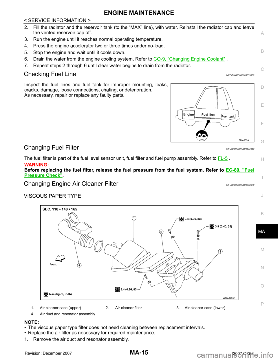
Checking Fuel LineINFOID:0000000003533868
Inspect the fuel lines and fuel tank for improper mounting, leaks,
cracks, damage, loose connections, chafing, or deterioration.
As necessary, repair or replace any faulty parts.
Changing Fuel FilterINFOID:0000000003533869
The fuel filter is part of the fuel level sensor unit, fuel filter and fuel pump assembly. Refer to FL-5 .
WARNING:
Before replacing the fuel filter, release the fuel pressure from the fuel system. Refer to EC-80, "
Fuel
Pressure Check".
Changing Engine Air Cleaner FilterINFOID:0000000003533870
VISCOUS PAPER TYPE
NOTE:
• The viscous paper type filter does not need cleaning between replacement intervals.
• Replace the air filter as necessary for required maintenance.
1. Remove the air duct and resonator assembly.
SMA803A
1. Air cleaner case (upper) 2. Air cleaner filter 3. Air cleaner case (lower)
4. Air duct and resonator assembly
WBIA0465E
Page 2384 of 3061
MA-22
< SERVICE INFORMATION >
CHASSIS AND BODY MAINTENANCE
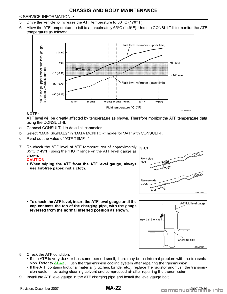
5. Drive the vehicle to increase the ATF temperature to 80° C (176° F).
6. Allow the ATF temperature to fall to approximately 65°C (149°F). Use the CONSULT-II to monitor the ATF
temperature as follows:
NOTE:
ATF level will be greatly affected by temperature as shown. Therefore monitor the ATF temperature data
using the CONSULT-II.
a. Connect CONSULT-II to data link connector.
b. Select “MAIN SIGNALS” in “DATA MONITOR” mode for “A/T” with CONSULT-II.
c. Read out the value of “ATF TEMP 1”.
7. Re-check the ATF level at ATF temperatures of approximately
65°C (149°F) using the “HOT” range on the ATF level gauge as
shown.
CAUTION:
• When wiping the ATF from the ATF level gauge, always
use lint-free paper, not a cloth.
• To check the ATF level, insert the ATF level gauge until the
cap contacts the top of the charging pipe, with the gauge
reversed from the normal inserted position as shown.
8. Check the ATF condition.
• If the ATF is very dark or has some burned smell, there may be an internal problem with the transmis-
sion. Refer to AT- 4 3
. Flush the transmission cooling system after repairing the transmission.
• If the ATF contains frictional material (clutches, bands, etc.), replace the radiator and flush the transmis-
sion cooler lines using cleaning solvent and compressed air after repairing the transmission.
9. Install the ATF level gauge in the ATF charging pipe and install the level gauge bolt.
SLIA0016E
WLIA0014E
SCIA1684E