2007 INFINITI QX56 RECOMMENDED ENGINE OIL
[x] Cancel search: RECOMMENDED ENGINE OILPage 1854 of 3061
EM-84
< SERVICE INFORMATION >
CYLINDER BLOCK
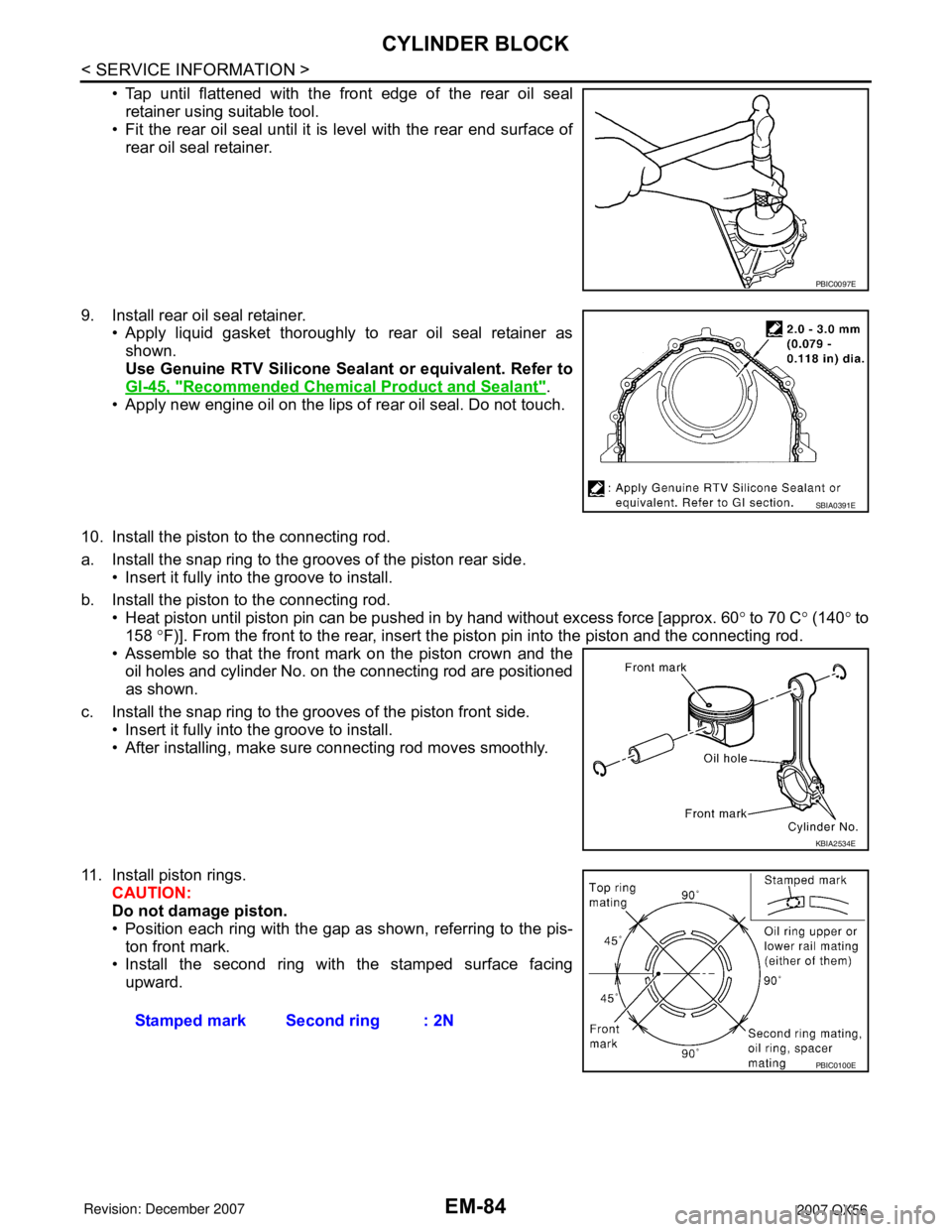
• Tap until flattened with the front edge of the rear oil seal
retainer using suitable tool.
• Fit the rear oil seal until it is level with the rear end surface of
rear oil seal retainer.
9. Install rear oil seal retainer.
• Apply liquid gasket thoroughly to rear oil seal retainer as
shown.
Use Genuine RTV Silicone Sealant or equivalent. Refer to
GI-45, "
Recommended Chemical Product and Sealant".
• Apply new engine oil on the lips of rear oil seal. Do not touch.
10. Install the piston to the connecting rod.
a. Install the snap ring to the grooves of the piston rear side.
• Insert it fully into the groove to install.
b. Install the piston to the connecting rod.
• Heat piston until piston pin can be pushed in by hand without excess force [approx. 60° to 70 C° (140° to
158 °F)]. From the front to the rear, insert the piston pin into the piston and the connecting rod.
• Assemble so that the front mark on the piston crown and the
oil holes and cylinder No. on the connecting rod are positioned
as shown.
c. Install the snap ring to the grooves of the piston front side.
• Insert it fully into the groove to install.
• After installing, make sure connecting rod moves smoothly.
11. Install piston rings.
CAUTION:
Do not damage piston.
• Position each ring with the gap as shown, referring to the pis-
ton front mark.
• Install the second ring with the stamped surface facing
upward.
PBIC0097E
SBIA0391E
KBIA2534E
Stamped mark Second ring : 2N
PBIC0100E
Page 1906 of 3061
DIFFERENTIAL GEAR OIL
FFD-7
< SERVICE INFORMATION >
C
E
F
G
H
I
J
K
L
MA
B
FFD
N
O
P
DIFFERENTIAL GEAR OIL
Changing Differential Gear OilINFOID:0000000003532588
DRAINING
1. Stop the engine.
2. Remove the drain plug from the front final drive assembly to drain the differential gear oil.
3. Install the drain plug with sealant applied on the threads to the front final drive assembly. Tighten to the
specified torque. Refer to FFD-13, "
Disassembly and Assembly".
• Use High Performance Thread Sealant or equivalent. Refer to GI-45, "
Recommended Chemical Product
and Sealant".
FILLING
1. Remove the filler plug from the front final drive assembly.
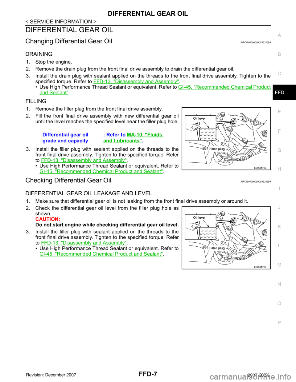
2. Fill the front final drive assembly with new differential gear oil
until the level reaches the specified level near the filler plug hole.
3. Install the filler plug with sealant applied on the threads to the
front final drive assembly. Tighten to the specified torque. Refer
to FFD-13, "
Disassembly and Assembly".
• Use High Performance Thread Sealant or equivalent. Refer to
GI-45, "
Recommended Chemical Product and Sealant".
Checking Differential Gear OilINFOID:0000000003532589
DIFFERENTIAL GEAR OIL LEAKAGE AND LEVEL
1. Make sure that differential gear oil is not leaking from the front final drive assembly or around it.
2. Check the differential gear oil level from the filler plug hole as
shown.
CAUTION:
Do not start engine while checking differential gear oil level.
3. Install the filler plug with sealant applied on the threads to the
front final drive assembly. Tighten to the specified torque. Refer
to FFD-13, "
Disassembly and Assembly".
• Use High Performance Thread Sealant or equivalent. Refer to
GI-45, "
Recommended Chemical Product and Sealant". Differential gear oil
grade and capacity: Refer to MA-10, "
Fluids
and Lubricants".
LDIA0176E
LDIA0176E
Page 1967 of 3061
GI-1
GENERAL INFORMATION
C
D
E
F
G
H
I
J
K
L
MB
GI
SECTION GI
N
O
P
CONTENTS
GENERAL INFORMATION
SERVICE INFORMATION ............................2
PRECAUTIONS ...................................................2
Description ................................................................2
Precaution for Supplemental Restraint System
(SRS) "AIR BAG" and "SEAT BELT PRE-TEN-
SIONER" ...................................................................
2
Precaution for NVIS/IVIS (NISSAN/INFINITI VE-
HICLE IMMOBILIZER SYSTEM - NATS) (If
Equipped) ..................................................................
2
General Precaution ...................................................3
Precaution for Three Way Catalyst ...........................4
Precaution for Fuel (Unleaded Premium Gasoline
Required) ..................................................................
4
Precaution for Multiport Fuel Injection System or
Engine Control System .............................................
5
Precaution for Hoses .................................................5
Precaution for Engine Oils ........................................6
Precaution for Air Conditioning .................................6
HOW TO USE THIS MANUAL ............................7
Description ................................................................7
Terms ........................................................................7
Units ..........................................................................7
Relation between Illustrations and Descriptions .......7
Contents ....................................................................8
Component ................................................................8
How to Follow Trouble Diagnosis ..............................9
How to Read Wiring Diagram ..................................13
Abbreviations ..........................................................20
SERVICE INFORMATION FOR ELECTRICAL
INCIDENT ...........................................................
22
How to Check Terminal ...........................................22
How to Perform Efficient Diagnosis for an Electri-
cal Incident ..............................................................
25
Control Units and Electrical Parts ............................32
CONSULT-II CHECKING SYSTEM ..................35
Description ...............................................................35
Function and System Application ............................35
Nickel Metal Hydride Battery Replacement .............36
Checking Equipment ...............................................36
CONSULT-II Start Procedure ..................................36
CONSULT-II Data Link Connector (DLC) Circuit .....38
LIFTING POINT .................................................40
Pantograph Jack ......................................................40
Garage Jack and Safety Stand ................................40
2-Pole Lift ................................................................40
TOW TRUCK TOWING .....................................42
Tow Truck Towing ...................................................42
Vehicle Recovery (Freeing a stuck vehicle) ............43
TIGHTENING TORQUE OF STANDARD
BOLTS ...............................................................
44
Tightening Torque Table .........................................44
RECOMMENDED CHEMICAL PRODUCTS
AND SEALANTS ...............................................
45
Recommended Chemical Product and Sealant .......45
IDENTIFICATION INFORMATION ....................46
Model Variation ........................................................46
Identification Number ...............................................47
Dimensions ..............................................................48
Wheels & Tires ........................................................48
TERMINOLOGY ................................................50
SAE J1930 Terminology List ...................................50
Page 1970 of 3061
GI-4
< SERVICE INFORMATION >
PRECAUTIONS
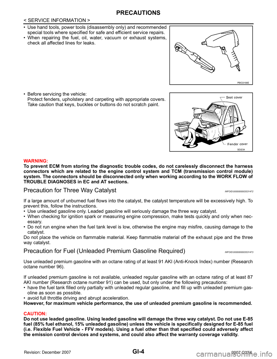
• Use hand tools, power tools (disassembly only) and recommended
special tools where specified for safe and efficient service repairs.
• When repairing the fuel, oil, water, vacuum or exhaust systems,
check all affected lines for leaks.
• Before servicing the vehicle:
Protect fenders, upholstery and carpeting with appropriate covers.
Take caution that keys, buckles or buttons do not scratch paint.
WARNING:
To prevent ECM from storing the diagnostic trouble codes, do not carelessly disconnect the harness
connectors which are related to the engine control system and TCM (transmission control module)
system. The connectors should be disconnected only when working according to the WORK FLOW of
TROUBLE DIAGNOSES in EC and AT sections.
Precaution for Three Way CatalystINFOID:0000000003531472
If a large amount of unburned fuel flows into the catalyst, the catalyst temperature will be excessively high. To
prevent this, follow the instructions.
• Use unleaded gasoline only. Leaded gasoline will seriously damage the three way catalyst.
• When checking for ignition spark or measuring engine compression, make tests quickly and only when nec-
essary.
• Do not run engine when the fuel tank level is low, otherwise the engine may misfire, causing damage to the
catalyst.
Do not place the vehicle on flammable material. Keep flammable material off the exhaust pipe and the three
way catalyst.
Precaution for Fuel (Unleaded Premium Gasoline Required)INFOID:0000000003531473
Use unleaded premium gasoline with an octane rating of at least 91 AKI (Anti-Knock Index) number (Research
octane number 96).
If unleaded premium gasoline is not available, unleaded regular gasoline with an octane rating of at least 87
AKI number (Research octane number 91) can be used, but only under the following precautions:
• have the fuel tank filled only partially with unleaded regular gasoline, and fill up with unleaded premium gas-
oline as soon as possible.
• avoid full throttle driving and abrupt acceleration.
However, for maximum vehicle performance, the use of unleaded premium gasoline is recommended.
CAUTION:
Do not use leaded gasoline. Using leaded gasoline will damage the three way catalyst. Do not use E-85
fuel (85% fuel ethanol, 15% unleaded gasoline) unless the vehicle is specifically designed for E-85 fuel
(i.e. Flexible Fuel Vehicle - FFV models). Using a fuel other than that specified could adversely affect
the emission control devices and systems, and could also affect the warranty coverage validity.
PBIC0190E
SGI234
Page 2348 of 3061
PRECAUTIONS
LU-3
< SERVICE INFORMATION >
C
D
E
F
G
H
I
J
K
L
MA
LU
N
P O
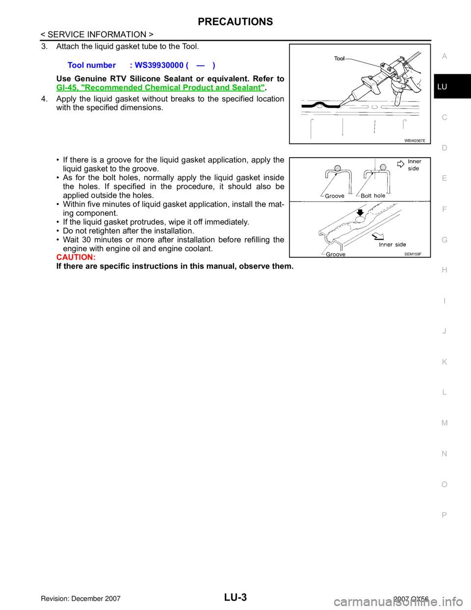
3. Attach the liquid gasket tube to the Tool.
Use Genuine RTV Silicone Sealant or equivalent. Refer to
GI-45, "
Recommended Chemical Product and Sealant".
4. Apply the liquid gasket without breaks to the specified location
with the specified dimensions.
• If there is a groove for the liquid gasket application, apply the
liquid gasket to the groove.
• As for the bolt holes, normally apply the liquid gasket inside
the holes. If specified in the procedure, it should also be
applied outside the holes.
• Within five minutes of liquid gasket application, install the mat-
ing component.
• If the liquid gasket protrudes, wipe it off immediately.
• Do not retighten after the installation.
• Wait 30 minutes or more after installation before refilling the
engine with engine oil and engine coolant.
CAUTION:
If there are specific instructions in this manual, observe them. Tool number : WS39930000 ( — )
WBIA0567E
SEM159F
Page 2353 of 3061
LU-8
< SERVICE INFORMATION >
ENGINE OIL
ENGINE OIL
InspectionINFOID:0000000003531555
OIL LEVEL
• Before starting the engine make sure the vehicle is parked on a flat
and level surface, then check the oil level. If the engine is already
running, turn it off and allow 10 minutes before checking.
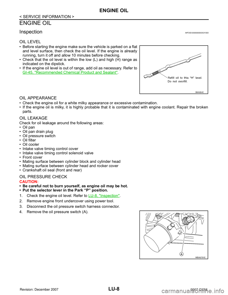
• Check that the oil level is within the low (L) and high (H) range as
indicated on the dipstick.
• If the engine oil level is out of range, add oil as necessary. Refer to
GI-45, "
Recommended Chemical Product and Sealant".
OIL APPEARANCE
• Check the engine oil for a white milky appearance or excessive contamination.
• If the engine oil is milky, it is highly probable that it is contaminated with engine coolant. Repair the broken
parts.
OIL LEAKAGE
Check for oil leakage around the following areas:
•Oil pan
• Oil pan drain plug
• Oil pressure switch
• Oil filter
• Oil cooler
• Intake valve timing control cover
• Intake valve timing control solenoid valve
• Front cover
• Mating surface between cylinder block and cylinder head
• Mating surface between cylinder head and rocker cover
• Crankshaft oil seal (front and rear)
OIL PRESSURE CHECK
CAUTION:
• Be careful not to burn yourself, as engine oil may be hot.
• Put the selector lever in the Park “P” position.
1. Check the engine oil level. Refer to LU-8, "
Inspection".
2. Remove engine front undercover using power tool.
3. Disconnect the oil pressure switch harness connector.
4. Remove the oil pressure switch (A).
SMA954C
WBIA0791E
Page 2354 of 3061
ENGINE OIL
LU-9
< SERVICE INFORMATION >
C
D
E
F
G
H
I
J
K
L
MA
LU
N
P O
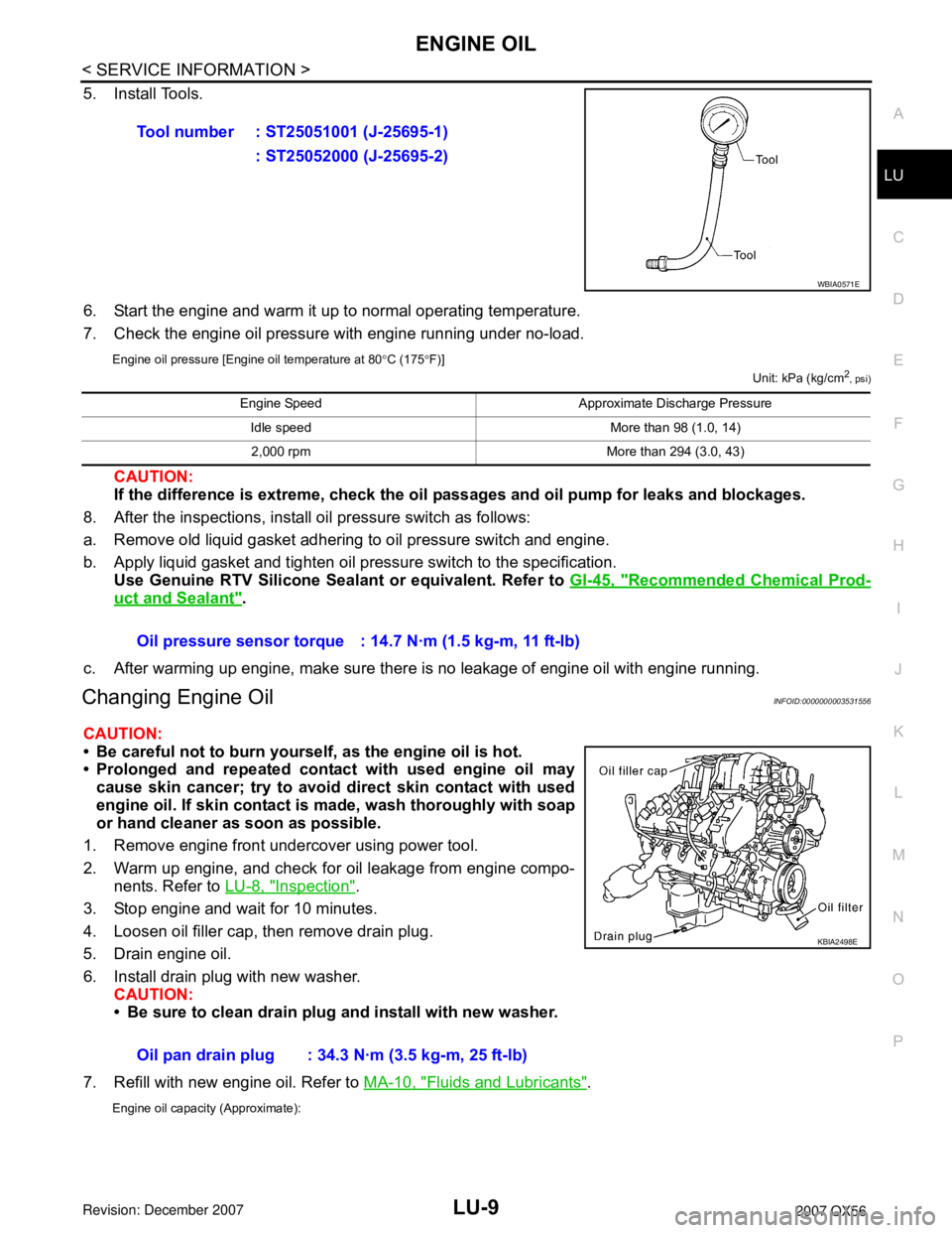
5. Install Tools.
6. Start the engine and warm it up to normal operating temperature.
7. Check the engine oil pressure with engine running under no-load.
Engine oil pressure [Engine oil temperature at 80°C (175°F)]
Unit: kPa (kg/cm2
, psi)
CAUTION:
If the difference is extreme, check the oil passages and oil pump for leaks and blockages.
8. After the inspections, install oil pressure switch as follows:
a. Remove old liquid gasket adhering to oil pressure switch and engine.
b. Apply liquid gasket and tighten oil pressure switch to the specification.
Use Genuine RTV Silicone Sealant or equivalent. Refer to GI-45, "
Recommended Chemical Prod-
uct and Sealant".
c. After warming up engine, make sure there is no leakage of engine oil with engine running.
Changing Engine OilINFOID:0000000003531556
CAUTION:
• Be careful not to burn yourself, as the engine oil is hot.
• Prolonged and repeated contact with used engine oil may
cause skin cancer; try to avoid direct skin contact with used
engine oil. If skin contact is made, wash thoroughly with soap
or hand cleaner as soon as possible.
1. Remove engine front undercover using power tool.
2. Warm up engine, and check for oil leakage from engine compo-
nents. Refer to LU-8, "
Inspection".
3. Stop engine and wait for 10 minutes.
4. Loosen oil filler cap, then remove drain plug.
5. Drain engine oil.
6. Install drain plug with new washer.
CAUTION:
• Be sure to clean drain plug and install with new washer.
7. Refill with new engine oil. Refer to MA-10, "
Fluids and Lubricants".
Engine oil capacity (Approximate):
Tool number : ST25051001 (J-25695-1)
: ST25052000 (J-25695-2)
WBIA0571E
Engine Speed Approximate Discharge Pressure
Idle speed More than 98 (1.0, 14)
2,000 rpm More than 294 (3.0, 43)
Oil pressure sensor torque : 14.7 N·m (1.5 kg-m, 11 ft-lb)
Oil pan drain plug : 34.3 N·m (3.5 kg-m, 25 ft-lb)
KBIA2498E
Page 2363 of 3061
MA-1
MAINTENANCE
C
D
E
F
G
H
I
J
K
M
SECTION MA
A
B
MA
N
O
P
CONTENTS
MAINTENANCE
SERVICE INFORMATION ............................2
PRECAUTIONS ...................................................2
Precaution for Supplemental Restraint System
(SRS) "AIR BAG" and "SEAT BELT PRE-TEN-
SIONER" ...................................................................
2
PREPARATION ...................................................3
Special Service Tool .................................................3
Commercial Service Tool ..........................................3
GENERAL MAINTENANCE ................................4
General Maintenance ................................................4
PERIODIC MAINTENANCE ................................6
Introduction of Periodic Maintenance ........................6
Maintenance for Off-road Driving (4WD only) ...........6
Schedule 1 ................................................................6
Schedule 2 ................................................................8
RECOMMENDED FLUIDS AND LUBRI-
CANTS ................................................................
10
Fluids and Lubricants ..............................................10
SAE Viscosity Number ............................................10
ENGINE MAINTENANCE ...................................12
Checking Drive Belts ...............................................12
Changing Engine Coolant .......................................12
Checking Fuel Line .................................................15
Changing Fuel Filter ................................................15
Changing Engine Air Cleaner Filter .........................15
Changing Engine Oil ................................................16
Changing Oil Filter ...................................................16
Changing Spark Plugs .............................................18
Checking EVAP Vapor Line .....................................19
CHASSIS AND BODY MAINTENANCE ...........20
Changing In-cabin Microfilter ...................................20
Checking Exhaust System .......................................21
Checking Automatic Transmission Fluid (ATF) .......21
Changing Automatic Transmission Fluid (ATF) .......23
Changing Transfer Fluid ..........................................23
Checking Transfer Fluid ..........................................24
Checking Propeller Shaft .........................................24
Checking Final Drive Oil ..........................................24
Changing Final Drive Oil ..........................................25
Balancing Wheels ....................................................25
Tire Rotation ............................................................27
Checking Brake Fluid Level and Leaks ...................27
CheckingBrake Line and Cables .............................27
Checking Disc Brake ...............................................27
Checking Steering Gear and Linkage ......................28
Checking Power Steering Fluid and Line ................28
Checking Axle and Suspension Parts .....................29
Lubricating Locks, Hinges and Hood Latches .........30
Checking Seat Belts, Buckles, Retractors, An-
chors and Adjusters .................................................
30