Page 1783 of 3061
DRIVE BELTSEM-13
< SERVICE INFORMATION >
C
DE
F
G H
I
J
K L
M A
EM
NP
O
DRIVE BELTS
Checking Drive BeltsINFOID:0000000003531521
WARNING:
Be sure to perform when the engine is stopped.
1. Remove air duct and resonator assembly when inspecting drive belt.
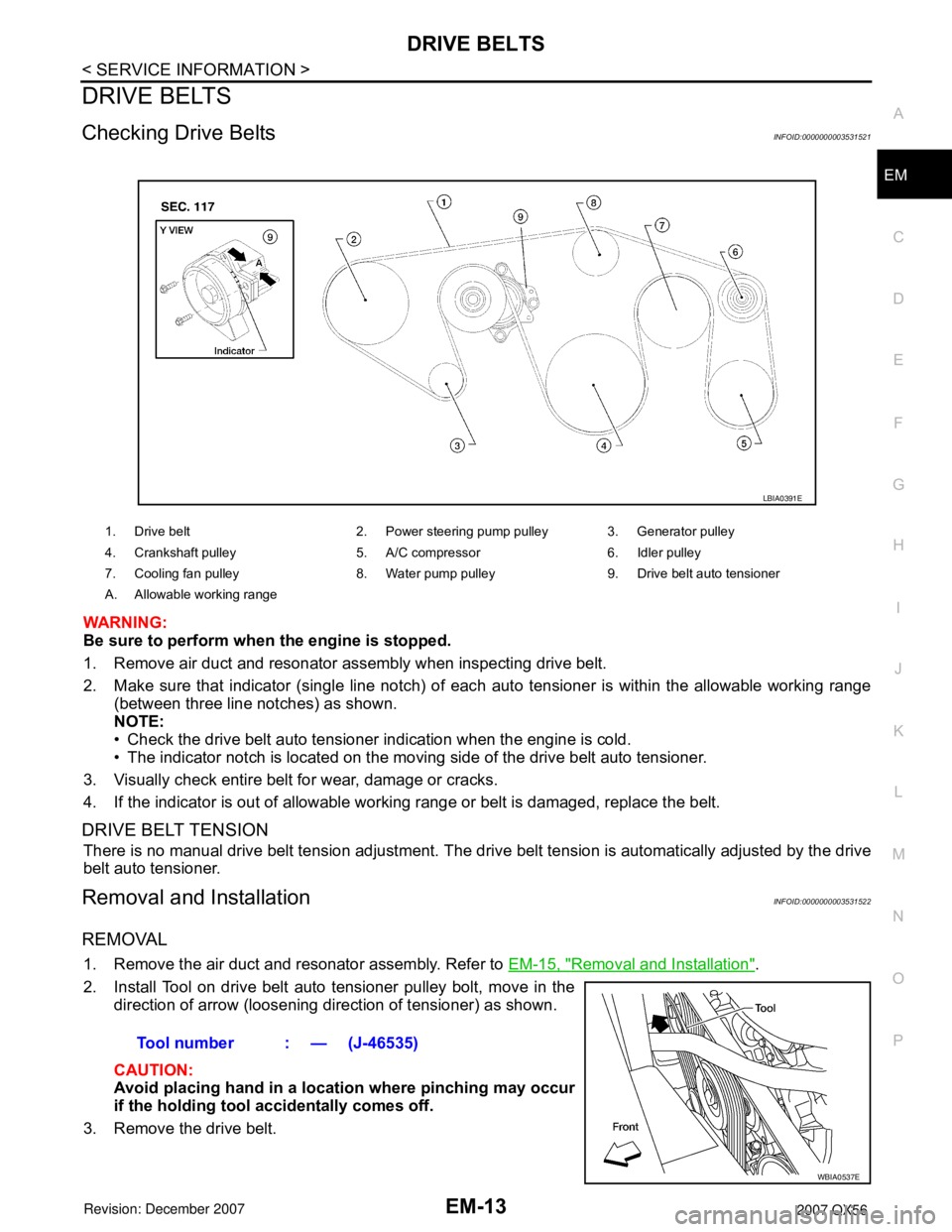
2. Make sure that indicator (single line notch) of eac
h auto tensioner is within the allowable working range
(between three line notches) as shown.
NOTE:
• Check the drive belt auto tensioner indication when the engine is cold.
• The indicator notch is located on the moving side of the drive belt auto tensioner.
3. Visually check entire belt for wear, damage or cracks.
4. If the indicator is out of allowable work ing range or belt is damaged, replace the belt.
DRIVE BELT TENSION
There is no manual drive belt tension adjustment. The driv e belt tension is automatically adjusted by the drive
belt auto tensioner.
Removal and InstallationINFOID:0000000003531522
REMOVAL
1. Remove the air duct and resonator assembly. Refer to EM-15, "Removal and Installation".
2. Install Tool on drive belt auto tensioner pulley bolt, move in the direction of arrow (loosening direction of tensioner) as shown.
CAUTION:
Avoid placing hand in a locat ion where pinching may occur
if the holding tool accidentally comes off.
3. Remove the drive belt.
1. Drive belt 2. Power steering pump pulley 3. Generator pulley
4. Crankshaft pulley 5. A/C compressor 6. Idler pulley
7. Cooling fan pulley 8. Water pump pulley 9. Drive belt auto tensioner
A. Allowable working range
LBIA0391E
Tool number : — (J-46535)
WBIA0537E
Page 1787 of 3061
INTAKE MANIFOLDEM-17
< SERVICE INFORMATION >
C
DE
F
G H
I
J
K L
M A
EM
NP
O
INTAKE MANIFOLD
Removal and InstallationINFOID:0000000003531526
REMOVAL
1. Partially drain the engine coolant. Refer to
CO-9, "Changing Engine Coolant".
WARNING:
To avoid the danger of being scalded, never drai n the engine coolant when the engine is hot.
2. Remove the engine room cover using power tool. Refer to EM-12, "
Removal and Installation".
3. Release the fuel pressure. Refer to EC-80, "
Fuel Pressure Check".
4. Remove the air duct and resonator assembly. Refer to EM-15, "
Removal and Installation".
5. Disconnect the fuel tube qui ck connector on the engine side.
1. Intake manifold 2. PCV hose 3. Gasket
4. Electric throttle control actuator 5. Water hose 6. Water hose
7. PCV hose 8. EVAP hose 9. EVAP canister purge control solenoid
valve
10. Bracket 11. Gasket
KBIA2461E
LBIA0395E
Page 1791 of 3061
EXHAUST MANIFOLD AND THREE WAY CATALYST
EM
-21
< ON-VE HICLE REPAIR >
C
D
E
F
G
H
I
J
K
L
M
A
EM
N
P
O
EXHAUST MANIFOLD AND THREE WA Y CATALYST
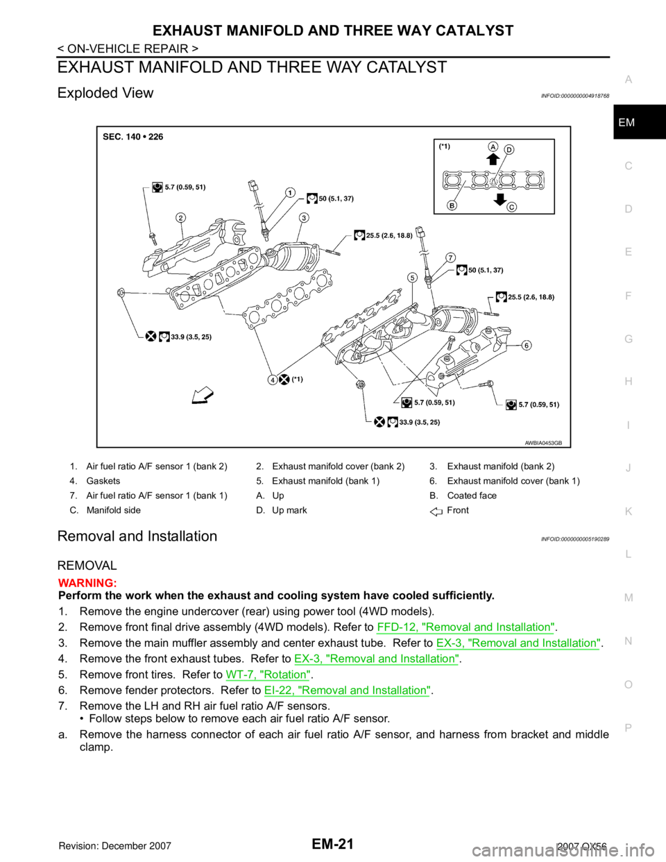
Exploded ViewINFOID:000 0000004918768
Removal and Installa tionINFOID:000 0000005190289
REMOVAL
WARNING:
Perf
o rm the wo rk when the exhau st and cooling system have co oled sufficiently.
1. Remove the engine undercover (rear) using power tool (4WD models).
2. Remove front final drive assembly (4WD models). Refer to
FFD-12, "Removal and Installation".
3. Remove the main muffler assembly and center exhaust tube. Refer to EX-3, "Removal and Installation".
4. Remove the front exhaust tubes. Refer to EX-3, "Removal and Installation".
5. Remove front tires. Refer to WT-7, "Rotation".
6. Remove fender protectors. Refer to EI-22, "Removal and Installation".
7. Remove the LH and RH air fuel ratio A/F sensors.
•Follow steps below to remove each air fuel ratio A/F sensor.
a. Remove the harness connector of each air fuel ratio A/F sensor, and harness from bracket and middle
clamp
.
1.Air fuel ratio A/F sensor 1 (bank 2)2. Exhaust manifold cover (bank 2)3. Exhaust manifold (bank 2)
4. Gaskets5.Exhaust manifold (bank 1)6. Exhaust manifold cover (bank 1)
7. Air fuel ratio A/F sensor 1 (bank 1)A.UpB.Coated face
C. Manifold sideD. Up markFront
AWBIA04 53GB
Page 1794 of 3061
EM-24
< SERVICE INFORMATION >
OIL PAN AND OIL STRAINER
OIL PAN AND OIL STRAINER
Removal and InstallationINFOID:0000000003531528
REMOVAL
WARNING:
To avoid the danger of being scalded, never drain the engine oil when the engine is hot.
1. Remove the engine. Refer to EM-74, "
Removal and Installation".
2. Remove the oil pan (lower) using the following steps.
a. Remove the oil pan (lower) bolts using power tool.
1. Oil pan (upper) 2. O-ring 3. O-ring
4. O-ring 5. O-ring (with collar) 6. Oil level gauge guide
7. Oil level gauge 8. O-ring 9. Connector bolt
10. Oil filter 11. Oil cooler 12. Relief valve
13. Oil pressure switch 14. Gasket 15. Drain plug
16. Oil pan (lower) 17. Oil strainer
KBIA2465E
KBIA2466E
Page 1810 of 3061
EM-40
< SERVICE INFORMATION >
TIMING CHAIN
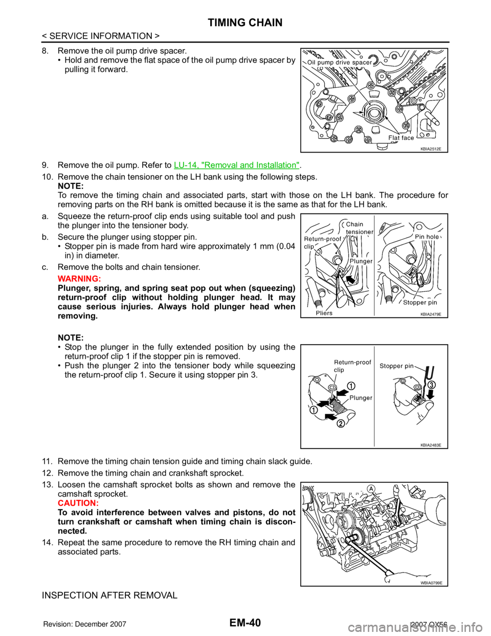
8. Remove the oil pump drive spacer.• Hold and remove the flat space of the oil pump drive spacer bypulling it forward.
9. Remove the oil pump. Refer to LU-14, "
Removal and Installation".
10. Remove the chain tensioner on the LH bank using the following steps. NOTE:
To remove the timing chain and associated parts, start with those on the LH bank. The procedure for
removing parts on the RH bank is omitted because it is the same as that for the LH bank.
a. Squeeze the return-proof clip ends using suitable tool and push the plunger into the tensioner body.
b. Secure the plunger using stopper pin. • Stopper pin is made from hard wire approximately 1 mm (0.04
in) in diameter.
c. Remove the bolts and chain tensioner.
WARNING:
Plunger, spring, and spring seat pop out when (squeezing)
return-proof clip without holding plunger head. It may
cause serious injuries. Alw ays hold plunger head when
removing.
NOTE:
• Stop the plunger in the fully extended position by using the return-proof clip 1 if the stopper pin is removed.
• Push the plunger 2 into the tensioner body while squeezing
the return-proof clip 1. Secure it using stopper pin 3.
11. Remove the timing chain tension guide and timing chain slack guide.
12. Remove the timing chain and crankshaft sprocket.
13. Loosen the camshaft sprocket bolts as shown and remove the camshaft sprocket.
CAUTION:
To avoid interference between valves and pistons, do not
turn crankshaft or camshaft wh en timing chain is discon-
nected.
14. Repeat the same procedure to remove the RH timing chain and associated parts.
INSPECTION AFTER REMOVAL
KBIA2512E
KBIA2479E
KBIA2483E
WBIA0799E
Page 1817 of 3061
CAMSHAFTEM-47
< SERVICE INFORMATION >
C
DE
F
G H
I
J
K L
M A
EM
NP
O
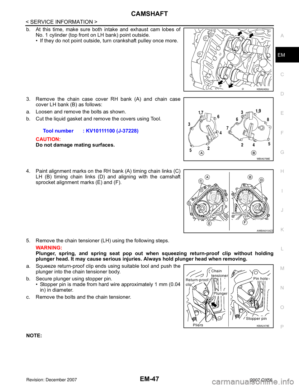
b. At this time, make sure both intake and exhaust cam lobes of
No. 1 cylinder (top front on LH bank) point outside.
• If they do not point outside, turn crankshaft pulley once more.
3. Remove the chain case cover RH bank (A) and chain case cover LH bank (B) as follows:
a. Loosen and remove the bolts as shown.
b. Cut the liquid gasket and remove the covers using Tool.
CAUTION:
Do not damage mating surfaces.
4. Paint alignment marks on the RH bank (A) timing chain links (C) LH (B) timing chain links (D) and aligning with the camshaft
sprocket alignment marks (E) and (F).
5. Remove the chain tensioner (LH) using the following steps. WARNING:
Plunger, spring, and spring seat pop out when squeezing return -proof clip without holding
plunger head. It may cause serious injuries. Always hold plunger head when removing.
a. Squeeze return-proof clip ends using suitable tool and push the plunger into the chain tensioner body.
b. Secure plunger using stopper pin. • Stopper pin is made from hard wire approximately 1 mm (0.04in) in diameter.
c. Remove the bolts and the chain tensioner.
NOTE:
KBIA0400J
Tool number : KV10111100 (J-37228)
WBIA0798E
AWBIA0154ZZ
KBIA2479E
Page 1818 of 3061
EM-48
< SERVICE INFORMATION >
CAMSHAFT
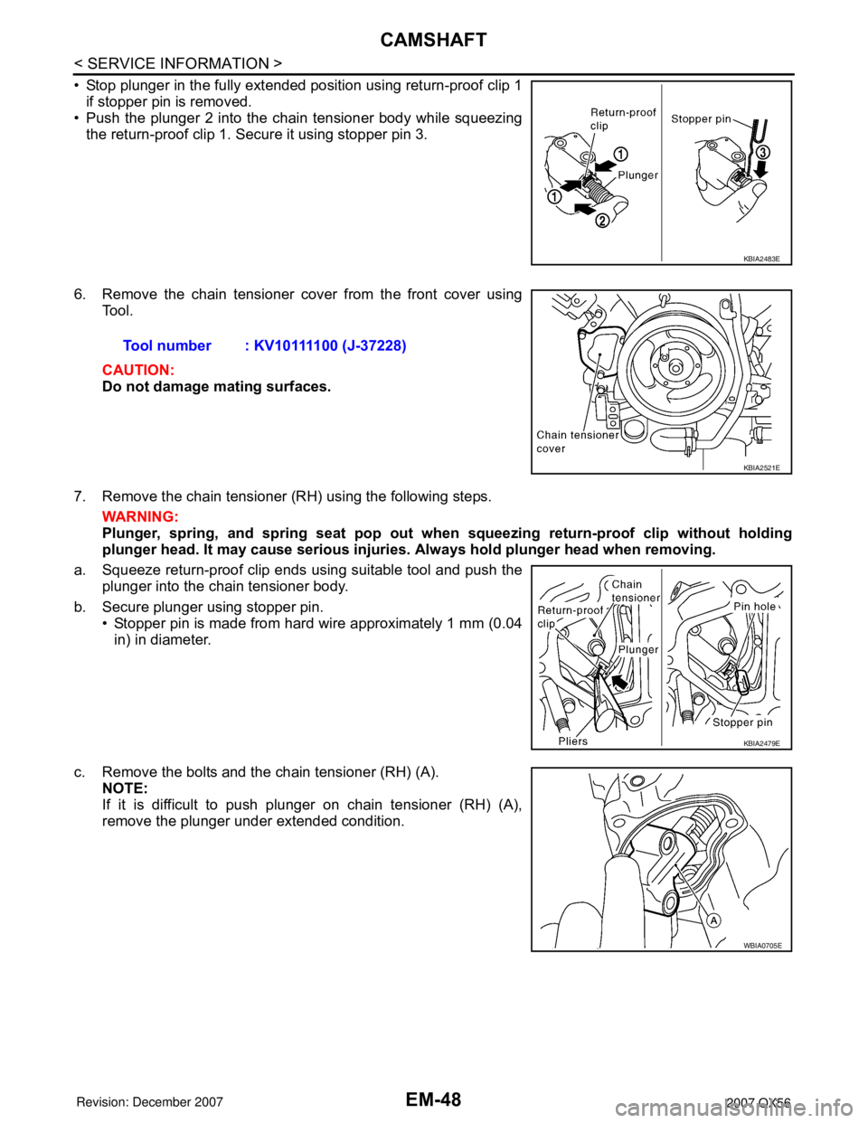
• Stop plunger in the fully extended position using return-proof clip 1if stopper pin is removed.
• Push the plunger 2 into the chain tensioner body while squeezing
the return-proof clip 1. Secure it using stopper pin 3.
6. Remove the chain tensioner cover from the front cover using Tool.
CAUTION:
Do not damage mating surfaces.
7. Remove the chain tensioner (RH) using the following steps. WARNING:
Plunger, spring, and spring seat pop out when squeezing return-proof clip without holding
plunger head. It may cause serious injuries. Always hold plunger head when removing.
a. Squeeze return-proof clip ends using suitable tool and push the plunger into the chain tensioner body.
b. Secure plunger using stopper pin. • Stopper pin is made from hard wire approximately 1 mm (0.04
in) in diameter.
c. Remove the bolts and the chain tensioner (RH) (A). NOTE:
If it is difficult to push plunger on chain tensioner (RH) (A),
remove the plunger under extended condition.
KBIA2483E
Tool number : KV10111100 (J-37228)
KBIA2521E
KBIA2479E
WBIA0705E
Page 1826 of 3061
EM-56
< SERVICE INFORMATION >
CAMSHAFT
2. Perform the following procedure so as to prevent the engine from being unintentionally started while
checking.
a. Release fuel pressure. Refer to EC-80, "
Fuel Pressure Check".
b. Disconnect ignition coil and injector harness connectors if practical.
3. Remove IVT control solenoid valve.
4. Crank engine, and then make sure that engine oil comes out from IVT control cover oil hole. End cranking
after checking.
WARNING:
Be careful not to touch rotating parts (drive be lts, idler pulley, and crankshaft pulley, etc.).
CAUTION:
• Engine oil may squirt from IVT control soleno id valve installation hole during cranking. Use a
shop cloth to prevent engine oil from splashin g on worker, engine components and vehicle.
• Do not allow engine oil to get on rubber compon ents such as drive belts or engine mount insula-
tors. Immediately wipe off any splashed engine oil.
5. Clean oil groove between oil strainer and IVT control solenoid valve if engine oil does not come out from IVT control valve cover oil hole. Refer to LU-7, "
Schematic".
6. Remove components between IVT control solenoid va lve and camshaft sprocket (INT), and then check
each oil groove for clogging.
• Clean oil groove if necessary.
7. After inspection, installation of the remaining components is in the reverse order of removal.
Valve ClearanceINFOID:0000000003531536
INSPECTION
NOTE:
Perform the following inspection after removal, installation or replacement of camshaft or valve-related parts,
or if there are unusual engine conditions due to changes in valve clearance over time (starting, idling, and/or
noise).
1. Warm up the engine. Then stop the engine.
2. Remove the engine cover and. Refer to EM-12, "
Removal and Installation".
3. Remove the battery cover. Refer to SC-8, "
Removal and Installation".
4. Remove the air cleaner and air duct assembly EM-15, "
Removal and Installation".
5. Remove the RH bank and LH bank rocker covers using power tool. Refer to EM-35, "
Removal and Instal-
lation".
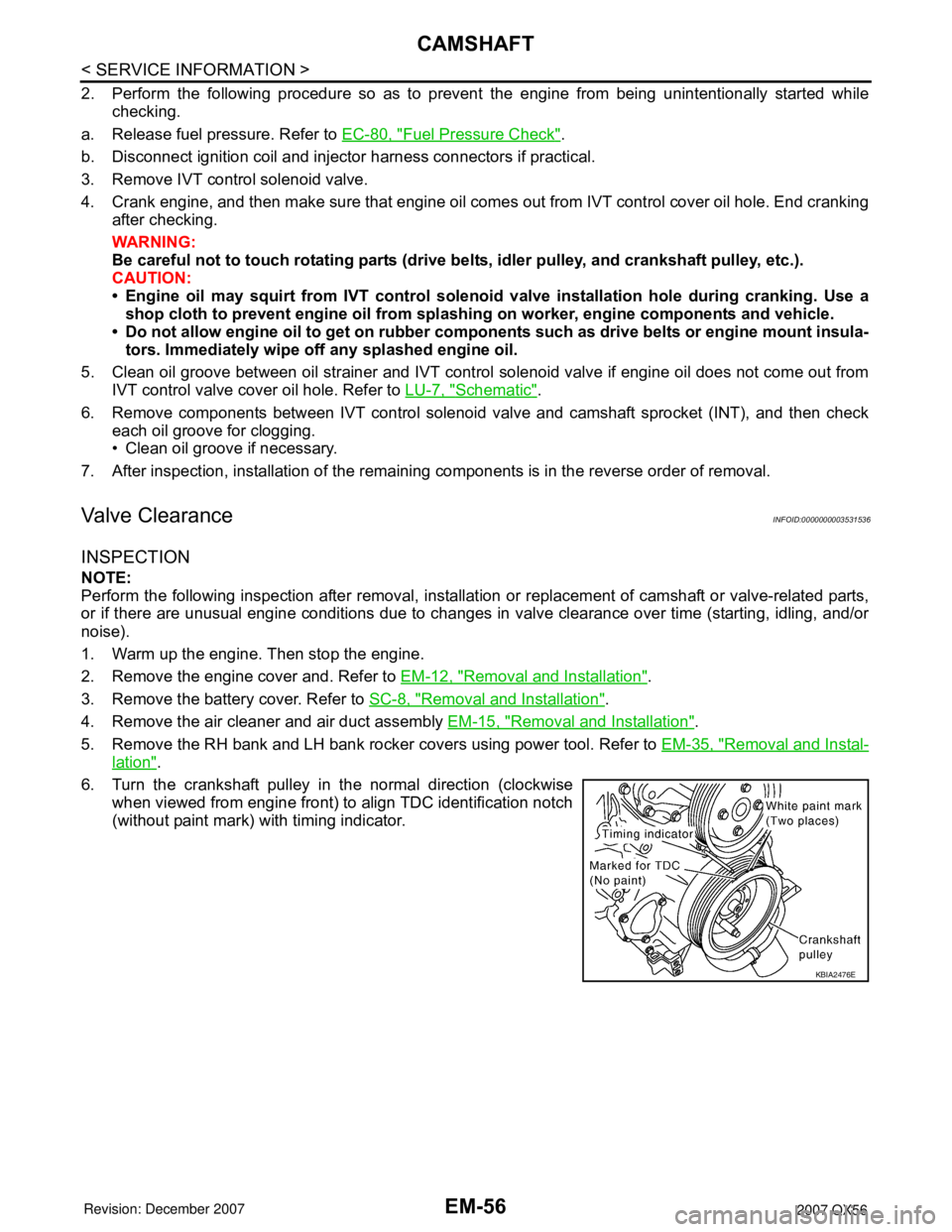
6. Turn the crankshaft pulley in the normal direction (clockwise when viewed from engine front) to align TDC identification notch
(without paint mark) with timing indicator.
KBIA2476E