2007 INFINITI QX56 rear door
[x] Cancel search: rear doorPage 1937 of 3061
FL-6
< SERVICE INFORMATION >
FUEL LEVEL SENSOR UNIT, FUEL FILTER AND FUEL PUMP ASSEMBLY
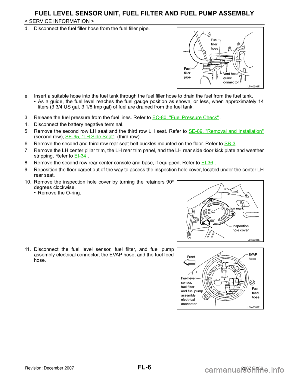
d. Disconnect the fuel filler hose from the fuel filler pipe.
e. Insert a suitable hose into the fuel tank through the fuel filler hose to drain the fuel from the fuel tank.
• As a guide, the fuel level reaches the fuel gauge position as shown, or less, when approximately 14
liters (3 3/4 US gal, 3 1/8 Imp gal) of fuel are drained from the fuel tank.
3. Release the fuel pressure from the fuel lines. Refer to EC-80, "
Fuel Pressure Check" .
4. Disconnect the battery negative terminal.
5. Remove the second row LH seat and the third row LH seat. Refer to SE-89, "
Removal and Installation"
(second row), SE-95, "LH Side Seat" (third row).
6. Remove the second and third row rear seat belt buckles mounted on the floor. Refer to SB-3
.
7. Remove the LH center pillar trim, the LH rear trim panel, and the LH rear side door kick plate and weather
stripping. Refer to EI-34
.
8. Remove the second row rear center console and base, if equipped. Refer to EI-36
.
9. Reposition the floor carpet out of the way to access the inspection hole cover, located under the center LH
rear seat.
10. Remove the inspection hole cover by turning the retainers 90°
degrees clockwise.
• Remove the O-ring.
11. Disconnect the fuel level sensor, fuel filter, and fuel pump
assembly electrical connector, the EVAP hose, and the fuel feed
hose.
LBIA0386E
LBIA0382E
LBIA0383E
Page 1942 of 3061
FUEL TANK
FL-11
< SERVICE INFORMATION >
C
D
E
F
G
H
I
J
K
L
MA
FL
N
P O
REMOVAL
WARNING:
Follow the “General Precautions” before working on the fuel system. Refer to GI-3, "
General Precau-
tion" .
1. Drain the fuel from the fuel tank, if necessary.
• Position the vehicle so it is level.
2. Remove the fuel filler cap to release the pressure from inside the fuel tank.
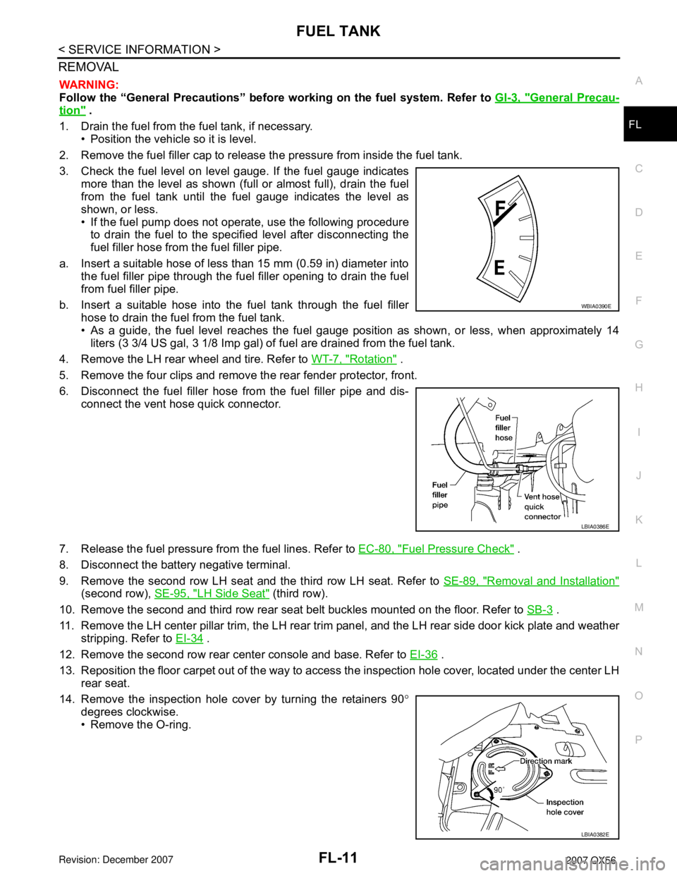
3. Check the fuel level on level gauge. If the fuel gauge indicates
more than the level as shown (full or almost full), drain the fuel
from the fuel tank until the fuel gauge indicates the level as
shown, or less.
• If the fuel pump does not operate, use the following procedure
to drain the fuel to the specified level after disconnecting the
fuel filler hose from the fuel filler pipe.
a. Insert a suitable hose of less than 15 mm (0.59 in) diameter into
the fuel filler pipe through the fuel filler opening to drain the fuel
from fuel filler pipe.
b. Insert a suitable hose into the fuel tank through the fuel filler
hose to drain the fuel from the fuel tank.
• As a guide, the fuel level reaches the fuel gauge position as shown, or less, when approximately 14
liters (3 3/4 US gal, 3 1/8 Imp gal) of fuel are drained from the fuel tank.
4. Remove the LH rear wheel and tire. Refer to WT-7, "
Rotation" .
5. Remove the four clips and remove the rear fender protector, front.
6. Disconnect the fuel filler hose from the fuel filler pipe and dis-
connect the vent hose quick connector.
7. Release the fuel pressure from the fuel lines. Refer to EC-80, "
Fuel Pressure Check" .
8. Disconnect the battery negative terminal.
9. Remove the second row LH seat and the third row LH seat. Refer to SE-89, "
Removal and Installation"
(second row), SE-95, "LH Side Seat" (third row).
10. Remove the second and third row rear seat belt buckles mounted on the floor. Refer to SB-3
.
11. Remove the LH center pillar trim, the LH rear trim panel, and the LH rear side door kick plate and weather
stripping. Refer to EI-34
.
12. Remove the second row rear center console and base. Refer to EI-36
.
13. Reposition the floor carpet out of the way to access the inspection hole cover, located under the center LH
rear seat.
14. Remove the inspection hole cover by turning the retainers 90°
degrees clockwise.
• Remove the O-ring.
WBIA0390E
LBIA0386E
LBIA0382E
Page 2020 of 3061
GW-1
BODY
C
D
E
F
G
H
J
K
L
M
SECTION GW
A
B
GW
N
O
P
CONTENTS
GLASSES, WINDOW SYSTEM & MIRRORS
SERVICE INFORMATION ............................3
PRECAUTIONS ...................................................3
Precaution for Supplemental Restraint System
(SRS) "AIR BAG" and "SEAT BELT PRE-TEN-
SIONER" ...................................................................
3
Handling for Adhesive and Primer ............................3
PREPARATION ...................................................4
Special Service Tool .................................................4
Commercial Service Tool ..........................................4
SQUEAK AND RATTLE TROUBLE DIAGNO-
SIS .......................................................................
5
Work Flow .................................................................5
Generic Squeak and Rattle Troubleshooting ............7
Diagnostic Worksheet ...............................................9
WINDSHIELD GLASS ........................................11
Removal and Installation .........................................11
REAR WINDOW GLASS AND MOLDING .........13
Removal and Installation .........................................13
POWER WINDOW SYSTEM ..............................15
Component Parts and Harness Connector Loca-
tion ..........................................................................
15
System Description .................................................15
CAN Communication System Description ...............18
Schematic ...............................................................19
Wiring Diagram - WINDOW- ...................................21
Main Power Window and Door Lock/Unlock
Switch Harness Connector Terminal Layout ...........
28
Terminal and Reference Value for Main Power
Window and Door Lock/Unlock Switch ...................
29
Power Window and Door Lock/Unlock Switch RH
Harness Connector Terminal Layout ......................
30
Terminal and Reference Value for Power Window
and Door Lock/Unlock Switch RH ...........................
30
Terminal and Reference Value for BCM .................31
Work Flow ...............................................................31
CONSULT-II Function (BCM) ..................................31
Trouble Diagnosis Symptom Chart ..........................32
BCM Power Supply and Ground Circuit Inspection
....
34
Main Power Window and Door Lock/Unlock
Switch Power Supply and Ground Circuit Inspec-
tion ...........................................................................
34
Power Window and Door Lock/Unlock Switch RH
Power Supply and Ground Circuit Inspection ..........
35
Front Power Window Motor LH Circuit Inspection ....36
Front Power Window Motor RH Circuit Inspection ....37
Limit Switch Circuit Inspection Front LH ..................37
Limit Switch Circuit Inspection Front RH .................38
Encoder Circuit Inspection Front LH ........................40
Encoder Circuit Inspection Front RH .......................41
Door Switch Check ..................................................43
Front Door Lock Assembly LH (Key Cylinder
Switch) Check ..........................................................
44
Power Window Serial Link Check Front LH and
RH ...........................................................................
46
Rear Power Window Control Unit LH or RH Power
Supply and Ground Circuit Inspection .....................
48
Rear Power Window Switch LH or RH Power Sup-
ply and Ground Circuit Inspection ...........................
49
Rear Power Window Motor LH Circuit Inspection ....50
Rear Power Window Motor RH Circuit Inspection ....50
Limit Switch Circuit Inspection Rear LH and RH .....51
Encoder Circuit Inspection Rear LH or RH ..............53
Power Window Serial Link Check Rear LH or RH ....54
Rear Power Vent Window Switch Circuit Inspec-
tion ...........................................................................
55
Rear Power Vent Window Motor LH Circuit In-
spection ...................................................................
55
Rear Power Vent Window Motor RH Circuit In-
spection ...................................................................
56
Rear Power Vent Window Relay (OPEN) Check ....56
Rear Power Vent Window Relay (CLOSE) Check ....57
FRONT DOOR GLASS AND REGULATOR .....59
Removal and Installation .........................................59
REAR DOOR GLASS AND REGULATOR .......62
Page 2021 of 3061

GW-2
Removal and Installation ........................................62
SIDE WINDOW GLASS .....................................65
Removal and Installation ........................................65
INSIDE MIRROR ................................................66
Wiring Diagram - I/MIRR - ......................................66
Removal and Installation ........................................66
REAR WINDOW DEFOGGER ...........................68
Component Parts and Harness Connector Loca-
tion ..........................................................................
68
System Description .................................................68
CAN Communication System Description ..............69
Schematic ...............................................................70
Wiring Diagram - DEF - ..........................................71
Terminal and Reference Value for BCM .................73
Terminal and Reference Value for IPDM E/R .........73
Work Flow ...............................................................74
CONSULT-II Function (BCM) .................................74
Trouble Diagnosis Symptom Chart .........................74
BCM Power Supply and Ground Circuit Inspection
...
75
Rear Window Defogger Switch Circuit Inspection ...75
Rear Window Defogger Circuit Inspection ..............76
Door Mirror Defogger Power Supply Circuit In-
spection ...................................................................
77
Door Mirror LH (Door Mirror Defogger) Circuit In-
spection ...................................................................
78
Door Mirror RH (Door Mirror Defogger) Circuit In-
spection ...................................................................
79
Rear Window Defogger Signal Inspection ..............80
Filament Check .......................................................80
Filament Repair .......................................................81
DOOR MIRROR .................................................83
Wiring Diagram - MIRROR - ...................................83
Door Mirror Assembly .............................................84
Door Mirror Glass ....................................................84
Page 2032 of 3061
REAR WINDOW GLASS AND MOLDING
GW-13
< SERVICE INFORMATION >
C
D
E
F
G
H
J
K
L
MA
B
GW
N
O
P
REAR WINDOW GLASS AND MOLDING
Removal and InstallationINFOID:0000000003533023
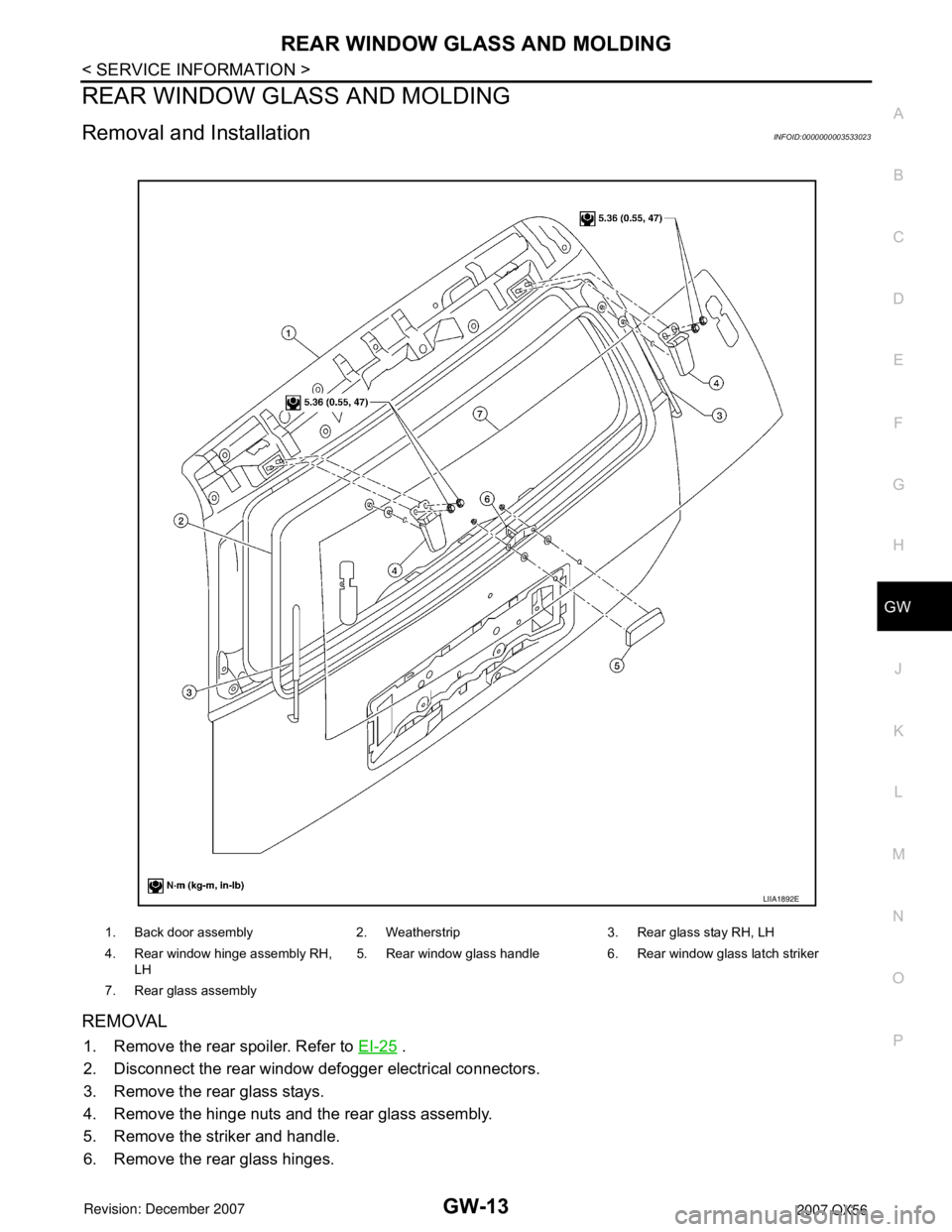
REMOVAL
1. Remove the rear spoiler. Refer to EI-25 .
2. Disconnect the rear window defogger electrical connectors.
3. Remove the rear glass stays.
4. Remove the hinge nuts and the rear glass assembly.
5. Remove the striker and handle.
6. Remove the rear glass hinges.
1. Back door assembly 2. Weatherstrip 3. Rear glass stay RH, LH
4. Rear window hinge assembly RH,
LH5. Rear window glass handle 6. Rear window glass latch striker
7. Rear glass assembly
LIIA1892E
Page 2034 of 3061
POWER WINDOW SYSTEM
GW-15
< SERVICE INFORMATION >
C
D
E
F
G
H
J
K
L
MA
B
GW
N
O
P
POWER WINDOW SYSTEM
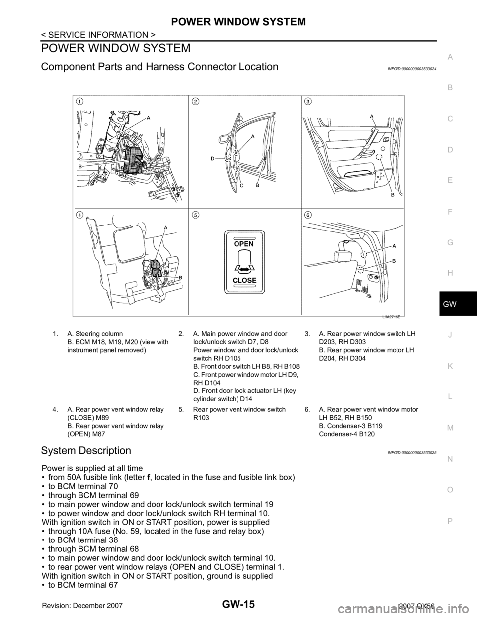
Component Parts and Harness Connector LocationINFOID:0000000003533024
System DescriptionINFOID:0000000003533025
Power is supplied at all time
• from 50A fusible link (letter f, located in the fuse and fusible link box)
• to BCM terminal 70
• through BCM terminal 69
• to main power window and door lock/unlock switch terminal 19
• to power window and door lock/unlock switch RH terminal 10.
With ignition switch in ON or START position, power is supplied
• through 10A fuse (No. 59, located in the fuse and relay box)
• to BCM terminal 38
• through BCM terminal 68
• to main power window and door lock/unlock switch terminal 10.
• to rear power vent window relays (OPEN and CLOSE) terminal 1.
With ignition switch in ON or START position, ground is supplied
• to BCM terminal 67
1. A. Steering column
B. BCM M18, M19, M20 (view with
instrument panel removed)2. A. Main power window and door
lock/unlock switch D7, D8
Power window and door lock/unlock
switch RH D105
B. Front door switch LH B8, RH B108
C. Front power window motor LH D9,
RH D104
D. Front door lock actuator LH (key
cylinder switch) D143. A. Rear power window switch LH
D203, RH D303
B. Rear power window motor LH
D204, RH D304
4. A. Rear power vent window relay
(CLOSE) M89
B. Rear power vent window relay
(OPEN) M875. Rear power vent window switch
R1036. A. Rear power vent window motor
LH B52, RH B150
B. Condenser-3 B119
Condenser-4 B120
LIIA2715E
Page 2035 of 3061

GW-16
< SERVICE INFORMATION >
POWER WINDOW SYSTEM
• to main power window and door lock/unlock switch terminal 17
• to power window and door lock/unlock switch RH terminal 11
• through body grounds M57, M61 and M79.
MANUAL OPERATION
Front Door LH
WINDOW UP
When the front LH switch in the main power window and door lock/unlock switch is pressed in the up position,
power is supplied
• through main power window and door lock/unlock switch terminal 8
• to front power window motor LH terminal 2.
Ground is supplied
• through main power window and door lock/unlock switch terminal 11
• to front power window motor LH terminal 1.
Then, the motor raises the window until the switch is released.
WINDOW DOWN
When the front LH switch in the main power window and door lock/unlock switch is pressed in the down posi-
tion, power is supplied
• through main power window and door lock/unlock switch terminal 11
• to front power window motor LH terminal 1.
Ground is supplied
• through main power window and door lock/unlock switch terminal 8
• to front power window motor LH terminal 2.
Then, the motor lowers the window until the switch is released.
Front Door RH
POWER WINDOW AND DOOR LOCK/UNLOCK SWITCH RH OPERATION
WINDOW UP
When the power window and door lock/unlock switch RH is pressed in the up position, power is supplied
• through power window and door lock/unlock switch RH terminal 8
• to front power window motor RH terminal 2.
Ground is supplied
• through power window and door lock/unlock switch RH terminal 9
• to front power window motor RH terminal 1.
Then, the motor raises the window until the switch is released.
WINDOW DOWN
When the power window and door lock/unlock switch RH is pressed in the down position, power is supplied
• through power window and door lock/unlock switch RH terminal 9
• to front power window motor RH terminal 1.
Ground is supplied
• through power window and door lock/unlock switch RH terminal 8
• to front power window motor RH terminal 2.
Then, the motor lowers the window until the switch is released.
MAIN POWER WINDOW AND DOOR LOCK/UNLOCK SWITCH OPERATION
Signal is sent
• through main power window and door lock/unlock switch terminal 14
• to power window and door lock/unlock switch RH terminal 16.
The operation of power window after receiving the signal is the same as operating the power window with
power window and door lock/unlock switch RH.
Rear Door (LH or RH)
REAR POWER WINDOW SWITCH LH OR RH OPERATION
WINDOW UP
When the rear power window switch LH or RH is pressed in the up position, power is supplied
• to rear power window control unit LH or RH terminal 13
• through rear power window control unit LH or RH terminal 7
• through rear power window switch LH or RH terminal 2 and 3
• through rear power window switch LH or RH terminal 5
• through rear power window control unit LH or RH terminal 11
• to rear power window motor LH or RH terminal 2.
Ground is supplied
• to rear power window control unit LH or RH terminal 15
Page 2036 of 3061
POWER WINDOW SYSTEM
GW-17
< SERVICE INFORMATION >
C
D
E
F
G
H
J
K
L
MA
B
GW
N
O
P
• through rear power window control unit LH or RH terminal 16
• through rear power window switch LH or RH terminal 1 and 7
• through rear power window switch LH or RH terminal 4
• through rear power window control unit LH or RH terminal 12
• to rear power window motor LH or RH terminal 1.
Then, the motor raises the window until the switch is released.
WINDOW DOWN
When the rear power window switch LH or RH is pressed in the down position, power is supplied
• to rear power window control unit LH or RH terminal 1
• through rear power window control unit LH or RH terminal 7
• through rear power window switch LH or RH terminal 2 and 3
• through rear power window switch LH or RH terminal 4
• through rear power window control unit LH or RH terminal 12
• to rear power window motor LH or RH terminal 1.
Ground is supplied
• to rear power window control unit LH or RH terminal 15
• through rear power window control unit LH or RH terminal 16
• through rear power window switch LH or RH terminal 1 and 7
• through rear power window switch LH or RH terminal 5
• through rear power window control unit LH or RH terminal 11
• to rear power window motor LH or RH terminal 2.
Then, the motor lowers the window until the switch is released.
MAIN POWER WINDOW AND DOOR LOCK/UNLOCK SWITCH OPERATION
Signal is sent
• through main power window and door lock/unlock switch terminal 14
• to rear power window control unit LH or RH terminal 1.
The operation of power window after receiving the signal is the same as operating the power window with rear
power window switch LH or RH.
VENT WINDOW CLOSE
When the rear power vent window switch is pressed in the close position, power is supplied
• to rear power vent window relay (CLOSE) terminal 5
• through rear power vent window relay (CLOSE) terminal 3
• to rear power vent window motors terminal 2.
Ground is supplied
• to rear power vent window relay (OPEN) terminal 4
• through rear power vent window relay (OPEN) terminal 3
• to rear power vent window motors terminal 1.
Then, the motors close the windows until the switch is released.
VENT WINDOW OPEN
When the main power window and door lock/unlock switch (rear LH) is pressed in the open position, power is
supplied
• to rear power vent window relay (OPEN) terminal 5
• through rear power vent window relay (OPEN) terminal 3
• to rear power vent window motors terminal 1.
Ground is supplied
• to rear power vent window relay (CLOSE) terminal 4
• through rear power vent window relay (CLOSE) terminal 3
• to rear power vent window motors terminal 2.
Then, the motors open the windows until the switch is released.
AUTO OPERATION
The power window AUTO feature enables the driver to open or close the window without holding the window
switch in the down or up position.
POWER WINDOW SERIAL LINK
Main power window and door lock/unlock switch, power window and door lock/unlock switch RH, rear power
window control units and BCM transmit and receive the signal by power window serial link.
The signal is transmitted from BCM to main power window and door lock/unlock switch and power window and
door lock/unlock switch RH
• Keyless power window down signal.
• Rear power window switch illumination.