Page 821 of 3061
BL-110
< SERVICE INFORMATION >
FRONT DOOR LOCK
FRONT DOOR LOCK
Component StructureINFOID:0000000003532979
Removal and InstallationINFOID:0000000003532980
REMOVAL
1. Remove the front door window regulator. Refer to GW-59, "Removal and Installation".
2. Remove the front door window rear glass run.
3. Remove the door side grommet, and the bolt (TORX T30) from
the grommet hole.
1. Grommet 2. Front door striker 3. Door lock assembly
4. Outside handle cable 5. Inside handle assembly 6. Inside handle cable
7. Door lock cable 8. Key cylinder rod (Driver side only) 9. Key cylinder
10. Outside handle bracket 11. Front gasket 12. Outside handle
13. Door key cylinder assembly (Driver
side) Outside handle escutcheon
(Passenger side)14. Rear gasket
WIIA0891E
PIIA3553E
Page 822 of 3061
FRONT DOOR LOCK
BL-111
< SERVICE INFORMATION >
C
D
E
F
G
H
J
K
L
MA
B
BL
N
O
P
4. While pulling the outside handle, remove the door key cylinder
assembly or escutcheon.
5. Separate the key cylinder rod from the door key cylinder assembly (if equipped).
6. While pulling the outside handle, slide it toward rear of vehicle to
remove.
7. Remove the front and rear gaskets.
8. Remove the TORX bolts (T30), and the door lock assembly.
PIIA3554E
LIIA0532E
PIIA3557E
PIIA1090E
Page 823 of 3061
BL-112
< SERVICE INFORMATION >
FRONT DOOR LOCK
9. While pulling the outside handle bracket, slide it toward the rear
of vehicle to remove it and the door lock assembly.
10. Disconnect the door lock actuator electrical connector.
11. Separate the outside handle cable connection from the outside
handle bracket.
INSTALLATION
Installation in the reverse order of removal.
CAUTION:
To install each rod, be sure to rotate the rod holder until a click is felt.
Disassembly and AssemblyINFOID:0000000003532981
DOOR KEY CYLINDER ASSEMBLY
Remove the key cylinder escutcheon pawl and remove the door key cylinder.
PIIA3558E
PIIA5059E
PIIA4136E
Page 824 of 3061
REAR DOOR LOCK
BL-113
< SERVICE INFORMATION >
C
D
E
F
G
H
J
K
L
MA
B
BL
N
O
P
REAR DOOR LOCK
Component StructureINFOID:0000000003532982
Removal and InstallationINFOID:0000000003532983
REMOVAL
1. Remove the rear door window and rear door module assembly. Refer to GW-62.
2. Remove door grommets, and remove outside handle nuts from grommet hole.
3. Remove outside handle.
4. Disconnect the door lock actuator connector.
5. Separate outside handle rod connection.
INSTALLATION
Installation is in the reverse order of removal.
WIIA0892E
Page 851 of 3061
BL-140
< SERVICE INFORMATION >
BODY REPAIR
5. Front pillar hinge brace (RH, LH)
6. Center pillar hinge brace
7. Outer front pillar reinforcement (RH, LH)
8. Center inner pillar (RH, LH)
9. Front inner pillar upper (RH, LH)
10. Inner roof side rail (RH, LH)
11. Roof with sunroof opening
12. Roof
13. Front roof rail
14. Sunroof reinforcement
15. Roof 1st bow
16. Roof 2nd bow
17. Roof 3rd bow
18. Roof 4th bow
19. Rear roof rail
20. Main back pillar (RH, LH)
21. Back pillar reinforcement (RH, LH)
22. Rear inner side panel (RH, LH)
23. Rear wheel housing (RH, LH)
24. Rear body side outer (RH, LH)
25. Front body side outer (RH, LH)
26. Front door assembly (RH, LH)
27. Rear door assembly (RH, LH)
28. Lift gate assembly
Page 1083 of 3061
DI-72
< SERVICE INFORMATION >
REAR VIEW MONITOR
2. Remove luggage side finishers LH. Refer to EI-39.
3. Disconnect rear view camera control unit electrical connector.
4. Remove screws (2) and remove rear view camera control unit.
INSTALLATION
Installation is in the reverse order of removal.
Removal and Installation of Rear View CameraINFOID:0000000003533549
REMOVAL
1. Remove back door lower finisher. Refer to EI-41.
2. Remove license lamp finisher. Refer to EI-23
.
3. Disconnect rear view camera connector.
4. Remove screws (2) and remove rear view camera.
INSTALLATION
Installation is in the reverse order of removal.
NOTE:
After installing rear view camera, perform side distance guideline correction procedure. Refer to DI-65, "
Side
Distance Guideline Correction".
LKIA0478E
LKIA0479E
Page 1730 of 3061

EI-1
BODY
C
D
E
F
G
H
J
K
L
M
SECTION EI
A
B
EI
N
O
P
CONTENTS
EXTERIOR & INTERIOR
SERVICE INFORMATION ............................2
PRECAUTIONS ...................................................2
Service Notice ...........................................................2
Precaution for Supplemental Restraint System
(SRS) "AIR BAG" and "SEAT BELT PRE-TEN-
SIONER" ...................................................................
2
PREPARATION ...................................................3
Special Service Tool .................................................3
Commercial Service Tool ..........................................3
SQUEAK AND RATTLE TROUBLE DIAGNO-
SIS .......................................................................
4
Work Flow .................................................................4
Generic Squeak and Rattle Troubleshooting ............6
Diagnostic Worksheet ...............................................8
CLIP AND FASTENER .......................................10
Description ..............................................................10
FRONT BUMPER ...............................................12
Removal and Installation .........................................12
REAR BUMPER .................................................14
Removal and Installation .........................................14
FRONT GRILLE .................................................16
Removal and Installation .........................................16
COWL TOP .........................................................17
Removal and Installation .........................................17
FRONT FENDER ................................................19
Removal and Installation .........................................19
OVER FENDER ..................................................20
Removal and Installation .........................................20
FENDER PROTECTOR ....................................22
Removal and Installation .........................................22
LICENSE LAMP FINISHER ..............................23
Removal and Installation .........................................23
RUNNING BOARDS .........................................24
Removal and Installation .........................................24
REAR SPOILER ................................................25
Removal and Installation .........................................25
ROOF RACK .....................................................26
Removal and Installation .........................................26
DOOR OUTSIDE MOLDING .............................27
Removal and Installation .........................................27
SIDE GUARD MOLDING ..................................29
Removal and Installation .........................................29
DOOR FINISHER ..............................................31
Removal and Installation .........................................31
BODY SIDE TRIM .............................................34
Removal and Installation .........................................34
FLOOR TRIM ....................................................36
Removal and Installation .........................................36
HEADLINING ....................................................37
Removal and Installation .........................................37
LUGGAGE FLOOR TRIM .................................39
Removal and Installation .........................................39
BACK DOOR TRIM ...........................................41
Removal and Installation .........................................41
Page 1754 of 3061

REAR SPOILER
EI-25
< SERVICE INFORMATION >
C
D
E
F
G
H
J
K
L
MA
B
EI
N
O
P
REAR SPOILER
Removal and InstallationINFOID:0000000003533131
Removal
1. Disconnect the negative and positive battery cables, then wait at least 3 minutes.
2. Remove back door trim. Refer to EI-41
.
3. Disconnect harness to high-mount stop lamp.
4. Disconnect washer tube.
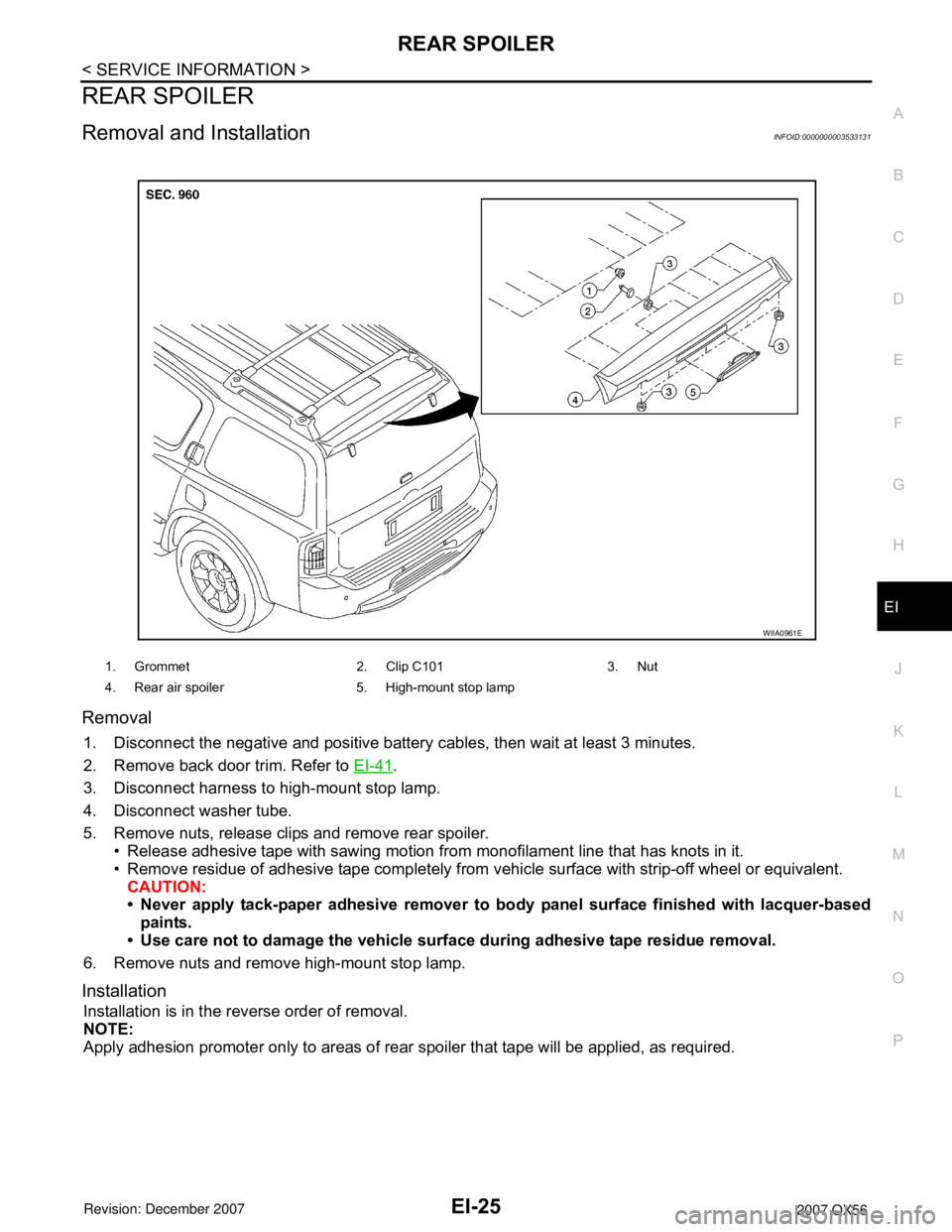
5. Remove nuts, release clips and remove rear spoiler.
• Release adhesive tape with sawing motion from monofilament line that has knots in it.
• Remove residue of adhesive tape completely from vehicle surface with strip-off wheel or equivalent.
CAUTION:
• Never apply tack-paper adhesive remover to body panel surface finished with lacquer-based
paints.
• Use care not to damage the vehicle surface during adhesive tape residue removal.
6. Remove nuts and remove high-mount stop lamp.
Installation
Installation is in the reverse order of removal.
NOTE:
Apply adhesion promoter only to areas of rear spoiler that tape will be applied, as required.
1. Grommet 2. Clip C101 3. Nut
4. Rear air spoiler 5. High-mount stop lamp
WIIA0961E