2007 INFINITI QX56 ignition
[x] Cancel search: ignitionPage 2247 of 3061

LT-40
< SERVICE INFORMATION >
AUTO LIGHT SYSTEM
How to Proceed with Trouble Diagnosis
INFOID:0000000003533376
1. Confirm the symptom or customer complaint.
2. Understand operation description and function description. Refer to LT-34, "
System Description" .
3. Carry out the Preliminary Check. Refer to LT-40, "
Preliminary Check" .
4. Check symptom and repair or replace the component. Refer to LT-42, "
Trouble Diagnosis Chart by Symp-
tom" .
5. Does the auto light system operate normally? If YES: GO TO 6. If NO: GO TO 4.
6. Inspection End.
Preliminary CheckINFOID:0000000003533377
SETTING CHANGE FUNCTIONS
• Sensitivity of auto light system can be adjusted using CONSULT-II. Refer to LT-40, "CONSULT-II Function
(BCM)" .
CHECK POWER SUPPLY AND GROUND CIRCUIT FOR BCM
Refer to BCS-15, "BCM Power Supply and Ground Circuit Inspection" .
CHECK POWER SUPPLY AND GROUND CIRCUIT FOR IPDM E/R
Refer to PG-26, "IPDM E/R Power/Ground Circuit Inspection" .
CONSULT-II Function (BCM)INFOID:0000000003533378
Refer to BCS-16, "CONSULT-II Function (BCM)".
CONSULT-II START PROCEDURE
Refer to GI-36, "CONSULT-II Start Procedure" .
WORK SUPPORT
Work Support Setting Item
• Delay timer setting can be selected and set from eight modes.
• Sensitivity of auto light can be selected and set from four modes.
DATA MONITOR
Display Item List
Work item Description
CUSTOM A/LIGHT SETTINGAuto light sensitivity can be changed in this mode. Sensitivity can be adjusted in four modes.
• MODE 1 (Normal-default)/ MODE 2 (Desensitized)/MODE 3 (Sensitive)/MODE4 (Insensitive)
ILL DELAY SETAuto light delay off timer period can be changed in this mode. Selects auto light delay off timer period
among eight modes.
• MODE 1 (45 sec.)/MODE 2 (OFF)/MODE 3 (30 sec.)/MODE 4 (60 sec.)/MODE 5 (90 sec.)/MODE
6 (120 sec.)/MODE 7 (150 sec.)/MODE 8 (180 sec.)
Monitor item Contents
IGN ON SW "ON/OFF" Displays "IGN position (ON)/OFF, ACC position (OFF)" judged from the ignition switch signal.
ACC ON SW "ON/OFF" Displays "ACC (ON)/OFF, Ignition OFF (OFF)" status judged from ignition switch signal.
HI BEAM SW "ON/OFF"Displays status (high beam switch: ON/Others: OFF) of high beam switch judged from lighting
switch signal.
HEAD LAMP SW 1 "ON/OFF"Displays status (headlamp switch 1: ON/Others: OFF) of headlamp switch 2 judged from light-
ing switch signal.
HEAD LAMP SW 2 "ON/OFF"Displays status (headlamp switch 2: ON/Others: OFF) of headlamp switch 2 judged from light-
ing switch signal.
LIGHT SW 1ST "ON/OFF"Displays status (lighting switch 1st position: ON/Others: OFF) of lighting switch judged from
lighting switch signal.
Page 2249 of 3061
LT-42
< SERVICE INFORMATION >
AUTO LIGHT SYSTEM
NOTE:
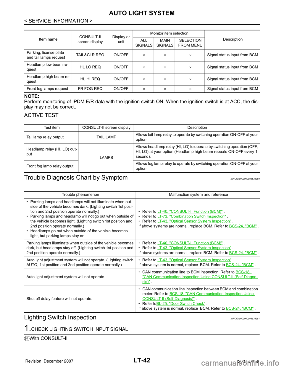
Perform monitoring of IPDM E/R data with the ignition switch ON. When the ignition switch is at ACC, the dis-
play may not be correct.
ACTIVE TEST
Trouble Diagnosis Chart by SymptomINFOID:0000000003533380
Lighting Switch InspectionINFOID:0000000003533381
1.CHECK LIGHTING SWITCH INPUT SIGNAL
With CONSULT-II
Item nameCONSULT-II
screen displayDisplay or
unitMonitor item selection
Description
ALL
SIGNALSMAIN
SIGNALSSELECTION
FROM MENU
Parking, license plate
and tail lamps requestTAIL&CLR REQ ON/OFF×× ×Signal status input from BCM
Headlamp low beam re-
questHL LO REQ ON/OFF×× ×Signal status input from BCM
Headlamp high beam re-
questHL HI REQ ON/OFF×× ×Signal status input from BCM
Front fog lamps request FR FOG REQ ON/OFF×× ×Signal status input from BCM
Test item CONSULT-II screen display Description
Tail lamp relay output TAIL LAMPAllows tail lamp relay to operate by switching operation ON-OFF at your
option.
Headlamp relay (HI, LO) out-
put
LAMPSAllows headlamp relay (HI, LO) to operate by switching operation (OFF,
HI, LO) at your option (Headlamp high beam repeats ON-OFF every 1
second).
Front fog lamp relay outputAllows fog lamp relay to operate by switching operation ON-OFF at your
option.
Trouble phenomenon Malfunction system and reference
• Parking lamps and headlamps will not illuminate when out-
side of the vehicle becomes dark. (Lighting switch 1st posi-
tion and 2nd position operate normally.)
• Parking lamps and headlamp will not go out when outside of
the vehicle becomes light. (Lighting switch 1st position and
2nd position operate normally.)
• Headlamps go out when outside of the vehicle becomes
light, but parking lamps stay on.•Refer to LT- 4 0 , "
CONSULT-II Function (BCM)" .
•Refer to LT- 7 3 , "
Combination Switch Inspection" .
•Refer to LT- 4 3 , "
Optical Sensor System Inspection" .
If above systems are normal, replace BCM. Refer to BCS-24, "
BCM" .
Parking lamps illuminate when outside of the vehicle becomes
dark, but headlamps stay off. (Lighting switch 1st position and
2nd position operate normally.)•Refer to LT- 4 0 , "
CONSULT-II Function (BCM)" .
•Refer to LT- 4 3 , "
Optical Sensor System Inspection" .
If above systems are normal, replace BCM. Refer to BCS-24, "
BCM" .
Auto light adjustment system will not operate. (Lighting switch
AUTO, 1st position and 2nd position operate normally.)•Refer to LT- 4 3 , "
Optical Sensor System Inspection" .
If above system is normal, replace BCM. Refer to BCS-24, "
BCM" .
Auto light adjustment system will not operate.• CAN communication line to BCM inspection. Refer to BCS-18,
"CAN Communication Inspection Using CONSULT-II (Self-Diagno-
sis)" .
Shut off delay feature will not operate.• CAN communication line inspection between BCM and combination
meter. Refer to BCS-18, "
CAN Communication Inspection Using
CONSULT-II (Self-Diagnosis)" .
•Refer toBL-25, "
Door Switch Check" .
If above system is normal, replace BCM. Refer to BCS-24, "
BCM" .
Page 2250 of 3061
AUTO LIGHT SYSTEM
LT-43
< SERVICE INFORMATION >
C
D
E
F
G
H
I
J
L
MA
B
LT
N
O
P
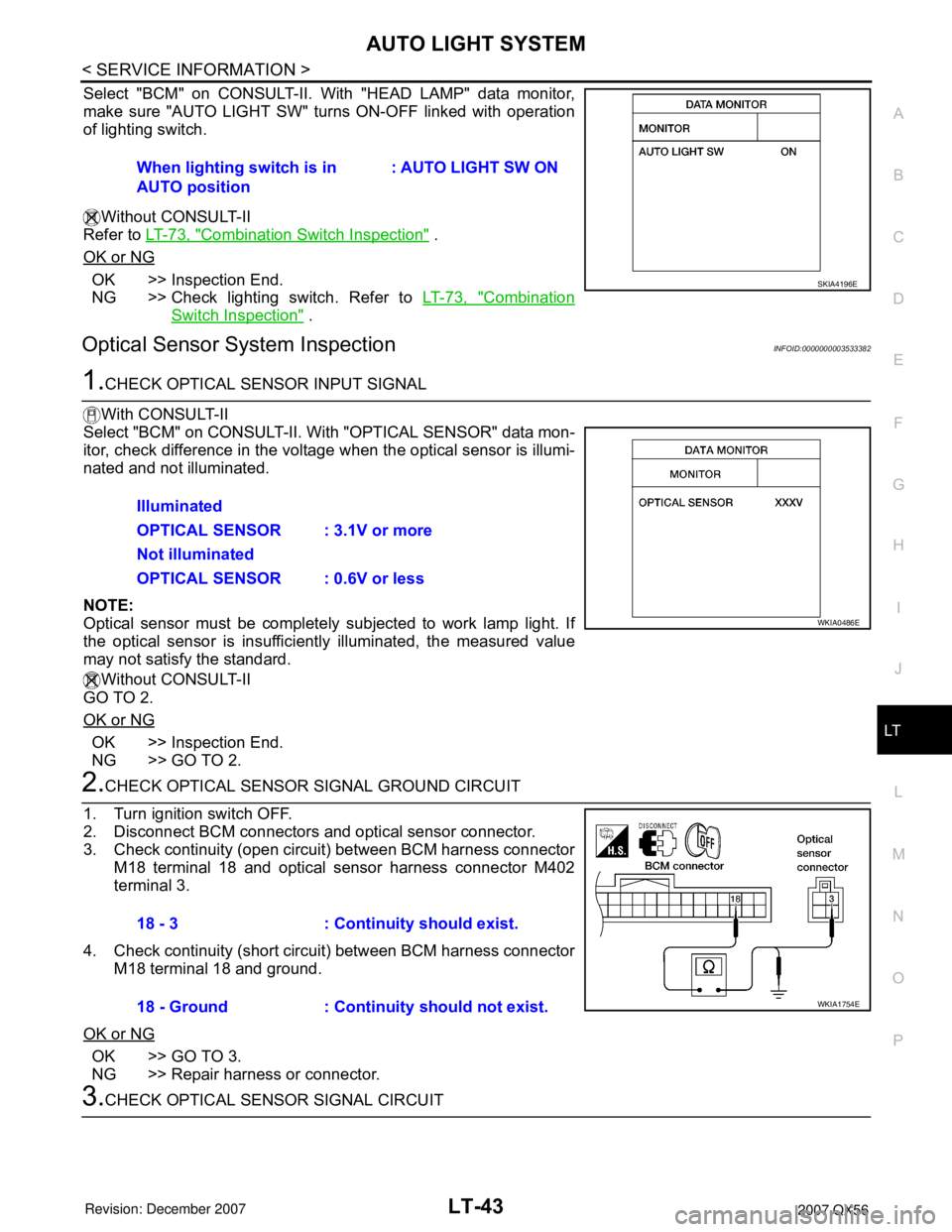
Select "BCM" on CONSULT-II. With "HEAD LAMP" data monitor,
make sure "AUTO LIGHT SW" turns ON-OFF linked with operation
of lighting switch.
Without CONSULT-II
Refer to LT-73, "
Combination Switch Inspection" .
OK or NG
OK >> Inspection End.
NG >> Check lighting switch. Refer to LT-73, "
Combination
Switch Inspection" .
Optical Sensor System InspectionINFOID:0000000003533382
1.CHECK OPTICAL SENSOR INPUT SIGNAL
With CONSULT-II
Select "BCM" on CONSULT-II. With "OPTICAL SENSOR" data mon-
itor, check difference in the voltage when the optical sensor is illumi-
nated and not illuminated.
NOTE:
Optical sensor must be completely subjected to work lamp light. If
the optical sensor is insufficiently illuminated, the measured value
may not satisfy the standard.
Without CONSULT-II
GO TO 2.
OK or NG
OK >> Inspection End.
NG >> GO TO 2.
2.CHECK OPTICAL SENSOR SIGNAL GROUND CIRCUIT
1. Turn ignition switch OFF.
2. Disconnect BCM connectors and optical sensor connector.
3. Check continuity (open circuit) between BCM harness connector
M18 terminal 18 and optical sensor harness connector M402
terminal 3.
4. Check continuity (short circuit) between BCM harness connector
M18 terminal 18 and ground.
OK or NG
OK >> GO TO 3.
NG >> Repair harness or connector.
3.CHECK OPTICAL SENSOR SIGNAL CIRCUITWhen lighting switch is in
AUTO position: AUTO LIGHT SW ON
SKIA4196E
Illuminated
OPTICAL SENSOR : 3.1V or more
Not illuminated
OPTICAL SENSOR : 0.6V or less
WKIA0486E
18 - 3 : Continuity should exist.
18 - Ground : Continuity should not exist.
WKIA1754E
Page 2252 of 3061

HEADLAMP AIMING CONTROL
LT-45
< SERVICE INFORMATION >
C
D
E
F
G
H
I
J
L
MA
B
LT
N
O
P
HEADLAMP AIMING CONTROL
System DescriptionINFOID:0000000003533384
The headlamp aiming system is controlled by the headlamp aiming switch.
Power is supplied at all times
• to ignition relay, located in the IPDM E/R (intelligent power distribution module engine room), and
• through 50A fusible link (letter f , located in the fuse and fusible link box)
• to BCM (body control module) terminal 70, and
• to headlamp low relay, located in the IPDM E/R (intelligent power distribution module engine room), and
• through 20A fuse (No. 53, located in the IPDM E/R)
• to CPU (central processing unit) of the IPDM E/R.
With the ignition switch in the ON or START position, power is supplied
• to ignition relay, located in the IPDM E/R, and
• through 10A fuse (No. 59, located in the fuse and relay box)
• to BCM terminal 38.
When the ignition switch is in the ACC or ON position, power is supplied
• through 10A fuse [No. 4, located in the fuse block (J/B)]
• to BCM terminal 11.
When the lighting switch is in the 2ND position or AUTO position (auto lights ON), the headlamp low relay
(located in the IPDM E/R) is energized. When energized, power is supplied
• through 15A fuse (No. 41, located in the IPDM E/R)
• through IPDM E/R terminal 26
• to front combination lamp LH and RH (headlamp aiming motor) terminal 8.
Ground is supplied
• to front combination lamp LH and RH (headlamp aiming motor) terminal 4
• through grounds E9, E15 and E24, and
• to front combination lamp LH and RH (headlamp aiming motor) terminal 7
• through headlamp aiming switch terminal 1
• through headlamp aiming switch terminal 2
• through grounds M57, M61 and M79.
With power and ground supplied, headlamp aiming motors operate according to the aiming switch position.
Page 2256 of 3061
FRONT FOG LAMP
LT-49
< SERVICE INFORMATION >
C
D
E
F
G
H
I
J
L
MA
B
LT
N
O
P
FRONT FOG LAMP
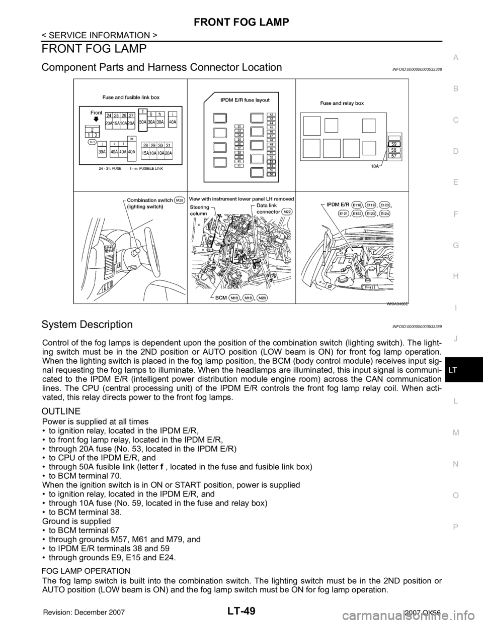
Component Parts and Harness Connector LocationINFOID:0000000003533388
System DescriptionINFOID:0000000003533389
Control of the fog lamps is dependent upon the position of the combination switch (lighting switch). The light-
ing switch must be in the 2ND position or AUTO position (LOW beam is ON) for front fog lamp operation.
When the lighting switch is placed in the fog lamp position, the BCM (body control module) receives input sig-
nal requesting the fog lamps to illuminate. When the headlamps are illuminated, this input signal is communi-
cated to the IPDM E/R (intelligent power distribution module engine room) across the CAN communication
lines. The CPU (central processing unit) of the IPDM E/R controls the front fog lamp relay coil. When acti-
vated, this relay directs power to the front fog lamps.
OUTLINE
Power is supplied at all times
• to ignition relay, located in the IPDM E/R,
• to front fog lamp relay, located in the IPDM E/R,
• through 20A fuse (No. 53, located in the IPDM E/R)
• to CPU of the IPDM E/R, and
• through 50A fusible link (letter f , located in the fuse and fusible link box)
• to BCM terminal 70.
When the ignition switch is in ON or START position, power is supplied
• to ignition relay, located in the IPDM E/R, and
• through 10A fuse (No. 59, located in the fuse and relay box)
• to BCM terminal 38.
Ground is supplied
• to BCM terminal 67
• through grounds M57, M61 and M79, and
• to IPDM E/R terminals 38 and 59
• through grounds E9, E15 and E24.
FOG LAMP OPERATION
The fog lamp switch is built into the combination switch. The lighting switch must be in the 2ND position or
AUTO position (LOW beam is ON) and the fog lamp switch must be ON for fog lamp operation.
WKIA3466E
Page 2257 of 3061
LT-50
< SERVICE INFORMATION >
FRONT FOG LAMP
With the fog lamp switch in the ON position, the CPU of the IPDM E/R grounds the coil side of the fog lamp
relay. The fog lamp relay then directs power
• through 20A fuse (No. 56, located in the IPDM E/R)
• through IPDM E/R terminal 50
• to front turn/fog lamp LH terminal 1, and
• through IPDM E/R terminal 51
• to front turn/fog lamp RH terminal 1.
Ground is supplied
• to front turn/fog lamp LH and RH terminal 3
• through grounds E9, E15 and E24.
With power and ground supplied, the front fog lamps illuminate.
COMBINATION SWITCH READING FUNCTION
Refer to BCS-3, "System Description" .
EXTERIOR LAMP BATTERY SAVER CONTROL
When the combination switch (lighting switch) is in the 2ND position (ON), the fog lamp switch is ON, and the
ignition switch is turned from ON or ACC to OFF, the battery saver control feature is activated.
Under this condition, the fog lamps (and headlamps) remain illuminated for 5 minutes, then the fog lamps (and
headlamps) are turned off.
Exterior lamp battery saver control mode can be changed by the function setting of CONSULT-II.
CAN Communication System DescriptionINFOID:0000000003533390
Refer to LAN-4, "CAN Communication System" .
Page 2264 of 3061
TURN SIGNAL AND HAZARD WARNING LAMPS
LT-57
< SERVICE INFORMATION >
C
D
E
F
G
H
I
J
L
MA
B
LT
N
O
P
TURN SIGNAL AND HAZARD WARNING LAMPS
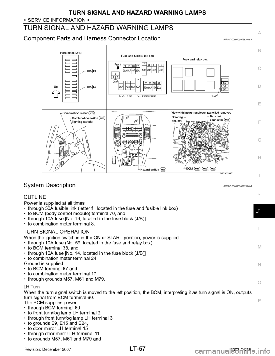
Component Parts and Harness Connector LocationINFOID:0000000003533403
System DescriptionINFOID:0000000003533404
OUTLINE
Power is supplied at all times
• through 50A fusible link (letter f , located in the fuse and fusible link box)
• to BCM (body control module) terminal 70, and
• through 10A fuse [No. 19, located in the fuse block (J/B)]
• to combination meter terminal 8.
TURN SIGNAL OPERATION
When the ignition switch is in the ON or START position, power is supplied
• through 10A fuse (No. 59, located in the fuse and relay box)
• to BCM terminal 38, and
• through 10A fuse [No. 14, located in the fuse block (J/B)]
• to combination meter terminal 24.
Ground is supplied
• to BCM terminal 67 and
• to combination meter terminal 17
• through grounds M57, M61 and M79.
LH Turn
When the turn signal switch is moved to the left position, the BCM, interpreting it as turn signal is ON, outputs
turn signal from BCM terminal 60.
The BCM supplies power
• through BCM terminal 60
• to front turn/fog lamp LH terminal 2
• through front turn/fog lamp LH terminal 3
• to grounds E9, E15 and E24,
• to door mirror LH terminal 15
• through door mirror LH terminal 11
• to grounds M57, M61 and M79 and
WKIA3554E
Page 2271 of 3061

LT-64
< SERVICE INFORMATION >
TURN SIGNAL AND HAZARD WARNING LAMPS
3. Perform preliminary check. Refer to LT-64, "Preliminary Check" .
4. Check symptom and repair or replace the component.
5. Do turn signal and hazard warning lamps operate normally? If YES: GO TO 6. If NO: GO TO 4.
6. Inspection End.
Preliminary CheckINFOID:0000000003533410
CHECK POWER SUPPLY AND GROUND CIRCUIT FOR BCM
Refer to BCS-15, "BCM Power Supply and Ground Circuit Inspection".
CONSULT-II Function (BCM)INFOID:0000000003533411
Refer to BCS-16, "CONSULT-II Function (BCM)".
CONSULT-II START PROCEDURE
Refer to GI-36, "CONSULT-II Start Procedure".
DATA MONITOR
Display Item List
ACTIVE TEST
Display Item List
Front Turn Signal Lamp Does Not OperateINFOID:0000000003533412
1.CHECK COMBINATION SWITCH INPUT SIGNAL
With CONSULT-II
Select "BCM" on CONSULT-II. With "FLASHER" data monitor, make
sure "TURN SIGNAL R" and "TURN SIGNAL L" turns ON-OFF
linked with operation of lighting switch.
Without CONSULT-II
Refer to LT-73, "
Combination Switch Inspection" .
OK or NG
OK >> GO TO 2.
NG >> Check lighting switch. Refer to LT-73, "
Combination Switch Inspection".
2.ACTIVE TEST
With CONSULT-II
Monitor item Contents
IGN ON SW "ON/OFF" Displays "IGN position (ON)/OFF, ACC position (OFF)" judged from the ignition switch signal.
HAZARD SW "ON/OFF" Displays "Hazard ON (ON)/Hazard OFF (OFF)" status, determined from hazard switch signal.
TURN SIGNAL R "ON/OFF" Displays "Turn right (ON)/Other (OFF)" status, determined from lighting switch signal.
TURN SIGNAL L "ON/OFF" Displays "Turn left (ON)/Other (OFF)" status, determined from lighting switch signal.
BRAKE SW "ON/OFF" Displays status of stop lamp switch.
Test item Description
FLASHER (RH) Turn signal lamp (right) can be operated by any ON-OFF operations.
FLASHER (LH) Turn signal lamp (left) can be operated by any ON-OFF operations.
When lighting switch is in
TURN RH position: TURN SIGNAL R ON
When lighting switch is in
TURN LH position: TURN SIGNAL L ON
SKIA4499E