Page 2374 of 3061

MA-12
< SERVICE INFORMATION >
ENGINE MAINTENANCE
ENGINE MAINTENANCE
Checking Drive BeltsINFOID:0000000003533866
WARNING:
Be sure to perform when the engine is stopped.
1. Remove air duct and resonator assembly (inlet) when inspecting drive belt.
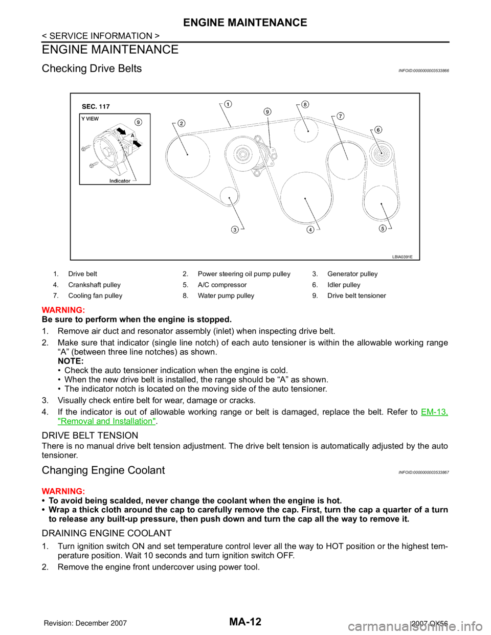
2. Make sure that indicator (single line notch) of each auto tensioner is within the allowable working range
“A” (between three line notches) as shown.
NOTE:
• Check the auto tensioner indication when the engine is cold.
• When the new drive belt is installed, the range should be “A” as shown.
• The indicator notch is located on the moving side of the auto tensioner.
3. Visually check entire belt for wear, damage or cracks.
4. If the indicator is out of allowable working range or belt is damaged, replace the belt. Refer to EM-13,
"Removal and Installation".
DRIVE BELT TENSION
There is no manual drive belt tension adjustment. The drive belt tension is automatically adjusted by the auto
tensioner.
Changing Engine CoolantINFOID:0000000003533867
WARNING:
• To avoid being scalded, never change the coolant when the engine is hot.
• Wrap a thick cloth around the cap to carefully remove the cap. First, turn the cap a quarter of a turn
to release any built-up pressure, then push down and turn the cap all the way to remove it.
DRAINING ENGINE COOLANT
1. Turn ignition switch ON and set temperature control lever all the way to HOT position or the highest tem-
perature position. Wait 10 seconds and turn ignition switch OFF.
2. Remove the engine front undercover using power tool.
1. Drive belt 2. Power steering oil pump pulley 3. Generator pulley
4. Crankshaft pulley 5. A/C compressor 6. Idler pulley
7. Cooling fan pulley 8. Water pump pulley 9. Drive belt tensioner
LBIA0391E
Page 2375 of 3061

ENGINE MAINTENANCE
MA-13
< SERVICE INFORMATION >
C
D
E
F
G
H
I
J
K
MA
B
MA
N
O
P
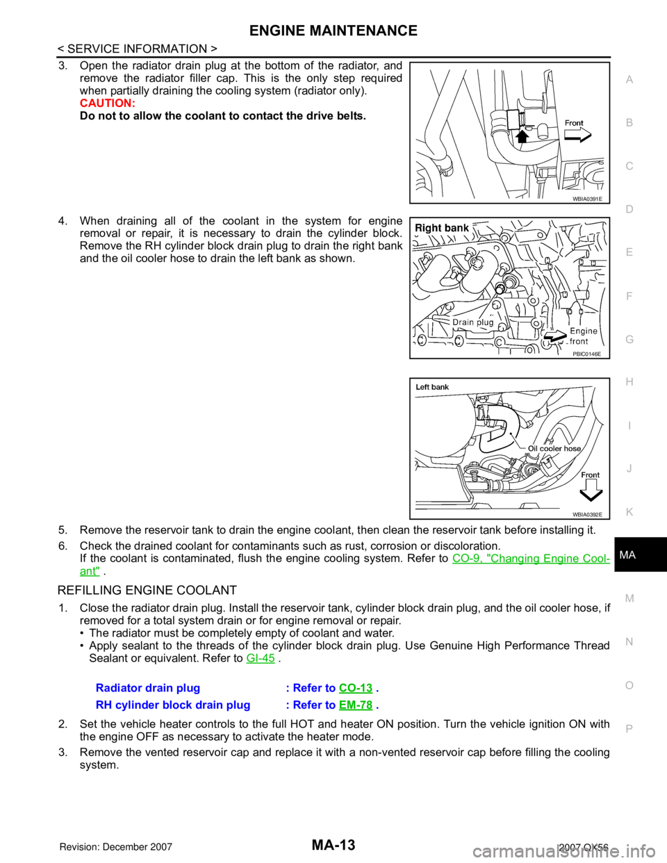
3. Open the radiator drain plug at the bottom of the radiator, and
remove the radiator filler cap. This is the only step required
when partially draining the cooling system (radiator only).
CAUTION:
Do not to allow the coolant to contact the drive belts.
4. When draining all of the coolant in the system for engine
removal or repair, it is necessary to drain the cylinder block.
Remove the RH cylinder block drain plug to drain the right bank
and the oil cooler hose to drain the left bank as shown.
5. Remove the reservoir tank to drain the engine coolant, then clean the reservoir tank before installing it.
6. Check the drained coolant for contaminants such as rust, corrosion or discoloration.
If the coolant is contaminated, flush the engine cooling system. Refer to CO-9, "
Changing Engine Cool-
ant" .
REFILLING ENGINE COOLANT
1. Close the radiator drain plug. Install the reservoir tank, cylinder block drain plug, and the oil cooler hose, if
removed for a total system drain or for engine removal or repair.
• The radiator must be completely empty of coolant and water.
• Apply sealant to the threads of the cylinder block drain plug. Use Genuine High Performance Thread
Sealant or equivalent. Refer to GI-45
.
2. Set the vehicle heater controls to the full HOT and heater ON position. Turn the vehicle ignition ON with
the engine OFF as necessary to activate the heater mode.
3. Remove the vented reservoir cap and replace it with a non-vented reservoir cap before filling the cooling
system.
WBIA0391E
PBIC0146E
WBIA0392E
Radiator drain plug : Refer to CO-13 .
RH cylinder block drain plug : Refer to EM-78
.
Page 2380 of 3061
MA-18
< SERVICE INFORMATION >
ENGINE MAINTENANCE
Changing Spark Plugs
INFOID:0000000003533873
REMOVAL
1. Remove the ignition coil. Refer to EM-28, "Removal and Installation" .
2. Remove the spark plug using suitable tool.
INSPECTION AFTER REMOVAL
• Do not use a wire brush for cleaning.
• If the spark plug tip is covered with carbon, a spark plug cleaner may be used.
1. Ignition coil 2. Spark plug
WBIA0796E
SEM294A
SMA773C
Cleaner air pressure
: Less than 588 kPa (5.9 bar, 6 kg/cm2 , 85 psi)
Cleaning time : Less than 20 seconds
Page 2403 of 3061

PG-1
ELECTRICAL
C
D
E
F
G
H
I
J
L
M
SECTION PG
A
B
PG
N
O
P
CONTENTS
POWER SUPPLY, GROUND & CIRCUIT ELEMENTS
SERVICE INFORMATION ............................2
PRECAUTIONS ...................................................2
Precaution for Supplemental Restraint System
(SRS) "AIR BAG" and "SEAT BELT PRE-TEN-
SIONER" ...................................................................
2
POWER SUPPLY ROUTING CIRCUIT ...............3
Schematic .................................................................3
Wiring Diagram - POWER - ......................................5
Fuse ........................................................................16
Fusible Link .............................................................16
Circuit Breaker (Built Into BCM) ..............................16
IPDM E/R (INTELLIGENT POWER DISTRI-
BUTION MODULE ENGINE ROOM) .................
17
System Description .................................................17
CAN Communication System Description ...............18
Function of Detecting Ignition Relay Malfunction ....18
CONSULT-II Function (IPDM E/R) ..........................18
Auto Active Test ......................................................20
Terminal and Reference Value for IPDM E/R .........22
IPDM E/R Terminal Arrangement ...........................26
IPDM E/R Power/Ground Circuit Inspection ...........26
Inspection with CONSULT-II (Self-Diagnosis) ........27
Removal and Installation of IPDM E/R ....................28
GROUND CIRCUIT ............................................29
Ground Distribution ..................................................29
HARNESS .........................................................39
Harness Layout .......................................................39
Wiring Diagram Codes (Cell Codes) .......................59
ELECTRICAL UNITS LOCATION ....................63
Electrical Units Location ..........................................63
HARNESS CONNECTOR .................................66
Description ...............................................................66
ELECTRICAL UNITS ........................................68
Terminal Arrangement .............................................68
STANDARDIZED RELAY .................................69
Description ...............................................................69
SUPER MULTIPLE JUNCTION (SMJ) .............71
Terminal Arrangement .............................................71
FUSE BLOCK - JUNCTION BOX (J/B) ............73
Terminal Arrangement .............................................73
FUSE AND FUSIBLE LINK BOX ......................74
Terminal Arrangement .............................................74
FUSE AND RELAY BOX ..................................75
Terminal Arrangement .............................................75
Page 2407 of 3061
POWER SUPPLY ROUTING CIRCUIT
PG-5
< SERVICE INFORMATION >
C
D
E
F
G
H
I
J
L
MA
B
PG
N
O
P
Wiring Diagram - POWER -INFOID:0000000003533831
BATTERY POWER SUPPLY — IGNITION SW. IN ANY POSITION
AWMWA0382G
Page 2412 of 3061
PG-10
< SERVICE INFORMATION >
POWER SUPPLY ROUTING CIRCUIT
ACCESSORY POWER SUPPLY — IGNITION SW. IN ACC OR ON
AWMWA0420G
Page 2413 of 3061
POWER SUPPLY ROUTING CIRCUIT
PG-11
< SERVICE INFORMATION >
C
D
E
F
G
H
I
J
L
MA
B
PG
N
O
P
IGNITION POWER SUPPLY — IGNITION SW. IN ON
WKWA3826E
Page 2414 of 3061
PG-12
< SERVICE INFORMATION >
POWER SUPPLY ROUTING CIRCUIT
IGNITION POWER SUPPLY — IGNITION SW. IN ON AND/OR START
WKWA3827E