2007 INFINITI QX56 ignition
[x] Cancel search: ignitionPage 2549 of 3061
SUNROOF
RF-17
< SERVICE INFORMATION >
C
D
E
F
G
H
J
K
L
MA
B
RF
N
O
P
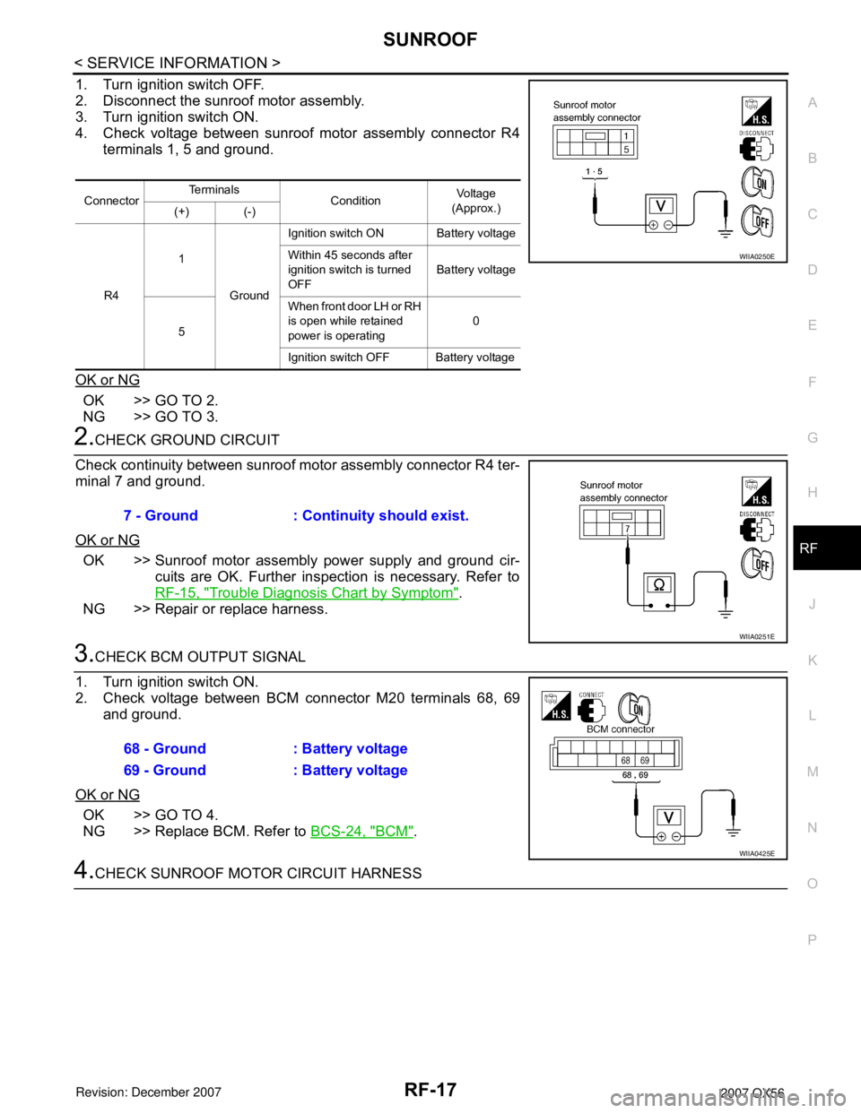
1. Turn ignition switch OFF.
2. Disconnect the sunroof motor assembly.
3. Turn ignition switch ON.
4. Check voltage between sunroof motor assembly connector R4
terminals 1, 5 and ground.
OK or NG
OK >> GO TO 2.
NG >> GO TO 3.
2.CHECK GROUND CIRCUIT
Check continuity between sunroof motor assembly connector R4 ter-
minal 7 and ground.
OK or NG
OK >> Sunroof motor assembly power supply and ground cir-
cuits are OK. Further inspection is necessary. Refer to
RF-15, "
Trouble Diagnosis Chart by Symptom".
NG >> Repair or replace harness.
3.CHECK BCM OUTPUT SIGNAL
1. Turn ignition switch ON.
2. Check voltage between BCM connector M20 terminals 68, 69
and ground.
OK or NG
OK >> GO TO 4.
NG >> Replace BCM. Refer to BCS-24, "
BCM".
4.CHECK SUNROOF MOTOR CIRCUIT HARNESS
ConnectorTe r m i n a l s
Condition Vo l ta g e
(Approx.)
(+) (-)
R41
GroundIgnition switch ON Battery voltage
Within 45 seconds after
ignition switch is turned
OFFBattery voltage
5When front door LH or RH
is open while retained
power is operating0
Ignition switch OFF Battery voltage
WIIA0250E
7 - Ground : Continuity should exist.
WIIA0251E
68 - Ground : Battery voltage
69 - Ground : Battery voltage
WIIA0425E
Page 2550 of 3061
RF-18
< SERVICE INFORMATION >
SUNROOF
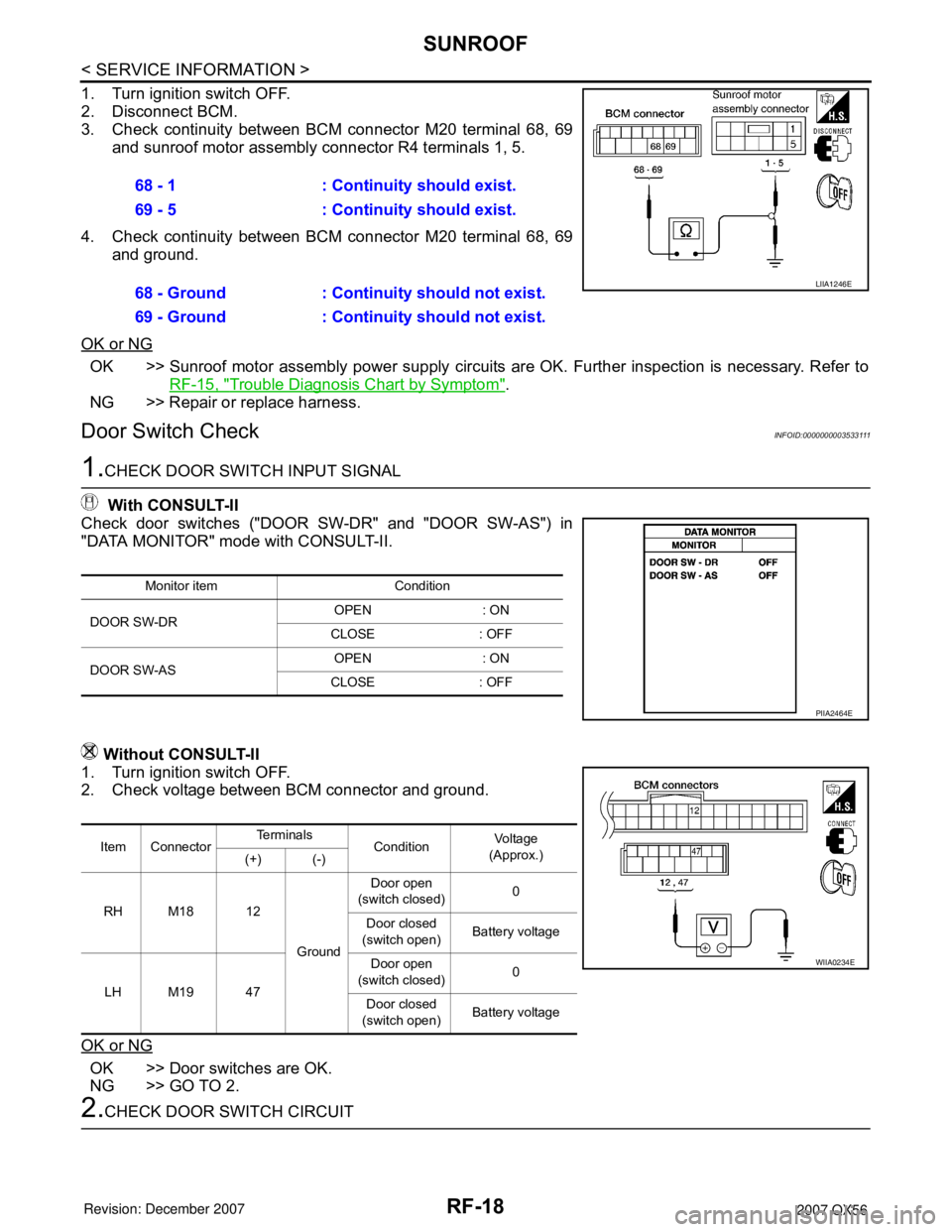
1. Turn ignition switch OFF.
2. Disconnect BCM.
3. Check continuity between BCM connector M20 terminal 68, 69
and sunroof motor assembly connector R4 terminals 1, 5.
4. Check continuity between BCM connector M20 terminal 68, 69
and ground.
OK or NG
OK >> Sunroof motor assembly power supply circuits are OK. Further inspection is necessary. Refer to
RF-15, "
Trouble Diagnosis Chart by Symptom".
NG >> Repair or replace harness.
Door Switch CheckINFOID:0000000003533111
1.CHECK DOOR SWITCH INPUT SIGNAL
With CONSULT-II
Check door switches ("DOOR SW-DR" and "DOOR SW-AS") in
"DATA MONITOR" mode with CONSULT-II.
Without CONSULT-II
1. Turn ignition switch OFF.
2. Check voltage between BCM connector and ground.
OK or NG
OK >> Door switches are OK.
NG >> GO TO 2.
2.CHECK DOOR SWITCH CIRCUIT 68 - 1 : Continuity should exist.
69 - 5 : Continuity should exist.
68 - Ground : Continuity should not exist.
69 - Ground : Continuity should not exist.
LIIA1246E
Monitor item Condition
DOOR SW-DROPEN : ON
CLOSE : OFF
DOOR SW-ASOPEN : ON
CLOSE : OFF
PIIA2464E
Item ConnectorTe r m i n a l s
ConditionVo l ta g e
(Approx.)
(+) (-)
RH M18 12
GroundDoor open
(switch closed)0
Door closed
(switch open)Battery voltage
LH M19 47Door open
(switch closed)0
Door closed
(switch open)Battery voltage
WIIA0234E
Page 2591 of 3061
RSU-1
SUSPENSION
C
D
F
G
H
I
J
K
L
M
SECTION RSU
A
B
RSU
N
O
PCONTENTS
REAR SUSPENSION
SERVICE INFORMATION ............................2
PRECAUTIONS ...................................................2
Precaution for Supplemental Restraint System
(SRS) "AIR BAG" and "SEAT BELT PRE-TEN-
SIONER" ...................................................................
2
Precaution for Rear Suspension ...............................2
PREPARATION ...................................................3
Commercial Service Tool ..........................................3
NOISE, VIBRATION AND HARSHNESS
(NVH) TROUBLESHOOTING .............................
4
NVH Troubleshooting Chart ......................................4
CAN COMMUNICATION .....................................5
System Description ...................................................5
TROUBLE DIAGNOSIS ......................................6
How to Perform Trouble Diagnosis for Quick and
Accurate Repair ........................................................
6
Component Parts and Harness Connector Loca-
tion ............................................................................
8
Wiring Diagram - A/SUSP - .......................................9
Basic Inspection ......................................................10
Chek Suspension Indicator Lamp Timing ...............11
Control Unit Input/Output Signal Standard ..............11
CONSULT-II Function (AIR LEVELIZER) ...............11
TROUBLE DIAGNOSIS FOR SELF-DIAG-
NOSTIC ITEMS ..................................................
14
Height Sensor System Inspection ...........................14
Exhaust Valve Solenoid System Inspection ............15
Compressor Motor, Compressor Motor Relay and
Circuit Inspection .....................................................
17
TROUBLE DIAGNOSES FOR SYMPTOMS ......19
Load Leveling Rear Air Suspension System Does
Not Operate .............................................................
19
Chek Suspension Indicator Lamp Stays On When
Ignition Switch Is Turned On ...................................
20
REAR SUSPENSION ASSEMBLY ...................21
Component ..............................................................21
On-Vehicle Inspection and Service .........................22
Wheel AlignmentInspection .....................................23
REAR SUSPENSION MEMBER .......................26
Removal and Installation .........................................26
SHOCK ABSORBER ........................................30
Removal and Installation .........................................30
SUSPENSION ARM ..........................................31
Removal and Installation .........................................31
FRONT LOWER LINK .......................................33
Removal and Installation .........................................33
REAR LOWER LINK & COIL SPRING .............35
Removal and Installation .........................................35
STABILIZER BAR .............................................37
Removal and Installation .........................................37
REAR LOAD LEVELING AIR SUSPENSION
COMPRESSOR ASSEMBLY ............................
38
Removal and Installation .........................................38
HEIGHT SENSOR .............................................40
Removal and Installation .........................................40
CONTROL UNIT ................................................42
Removal and Installation .........................................42
Initialization Procedure ............................................42
SERVICE DATA AND SPECIFICATIONS
(SDS) .................................................................
43
Wheel Alignment .....................................................43
Ball Joint ..................................................................43
Wheelarch Height (Unladen*1) ................................44
Page 2601 of 3061
TROUBLE DIAGNOSIS
RSU-11
< SERVICE INFORMATION >
C
D
F
G
H
I
J
K
L
MA
B
RSU
N
O
P
POWER SYSTEM TERMINAL LOOSENESS AND BATTERY INSPECTION
Make sure the battery positive cable, negative cable and ground connection are not loose. In addition, make
sure the battery is sufficiently charged.
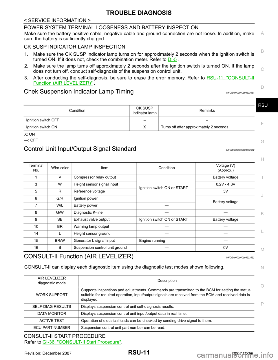
CK SUSP INDICATOR LAMP INSPECTION
1. Make sure the CK SUSP indicator lamp turns on for approximately 2 seconds when the ignition switch is
turned ON. If it does not, check the combination meter. Refer to DI-5
.
2. Make sure the lamp turns off approximately 2 seconds after the ignition switch is turned ON. If the lamp
does not turn off, conduct self-diagnosis of the suspension control unit.
3. After conducting the self-diagnosis, be sure to erase the error memory. Refer to RSU-11, "
CONSULT-II
Function (AIR LEVELIZER)" .
Chek Suspension Indicator Lamp TimingINFOID:0000000003532661
X: ON
—: OFF
Control Unit Input/Output Signal StandardINFOID:0000000003532662
CONSULT-II Function (AIR LEVELIZER)INFOID:0000000003532663
CONSULT-II can display each diagnostic item using the diagnostic test modes shown following.
CONSULT-II START PROCEDURE
Refer to GI-36, "CONSULT-II Start Procedure".
ConditionCK SUSP
indicator lampRemarks
Ignition switch OFF – –
Ignition switch ON X Turns off after approximately 2 seconds.
Te r m i n a l
No.Wire color Item ConditionVoltage (V)
(Approx.)
1 V Compressor relay output
Ignition switch ON or STARTBattery voltage
3 W Height sensor signal input 0.2V - 4.8V
5 R Reference voltage 5V
6 G/R Ignition power
Battery voltage
7W/LBattery power —
8 G/W Diagnostic K-line — —
9 SB Exhaust valve output Ignition switch ON or START Battery voltage
10 BR Warning lamp output — —
14 L Height sensor ground — —
15 BR/W Generator L signal input Engine running —
16 B Suspension control unit ground — 0V
AIR LEVELIZER
diagnostic modeDescription
WORK SUPPORTSupports inspections and adjustments. Commands are transmitted to the BCM for setting the status
suitable for required operation, input/output signals are received from the BCM and received data is
displayed.
SELF-DIAG RESULTS Displays suspension control unit self-diagnosis results.
DATA MONITOR Displays suspension control unit input/output data in real time.
ACTIVE TEST Operation of electrical loads can be checked by sending drive signal to them.
ECU PART NUMBER Suspension control unit part number can be read.
Page 2604 of 3061
RSU-14
< SERVICE INFORMATION >
TROUBLE DIAGNOSIS FOR SELF-DIAGNOSTIC ITEMS
TROUBLE DIAGNOSIS FOR SELF-DIAGNOSTIC ITEMS
Height Sensor System InspectionINFOID:0000000003532664
INSPECTION PROCEDURE
1.SELF-DIAGNOSIS RESULT CHECK
Check self-diagnosis results.
Is the above displayed in the self-diagnosis display items?
YES >> GO TO 3.
NO >> GO TO 2.
2.DATA MONITOR CHECK
Conduct data monitor of "HEIGT SEN" to check if the status is normal.
OK or NG
OK >> Inspection End.
NG >> GO TO 3.
3.CONNECTOR INSPECTION
1. Disconnect suspension control unit connector B3 and height sensor C8.
2. Check the terminals for deformation, disconnection, looseness or damage.
OK or NG
OK >> GO TO 4.
NG >> Repair or replace as necessary.
4.CHECK HEIGHT SENSOR POWER
1. Reconnect the suspension control unit connector.
2. Turn the ignition switch ON.
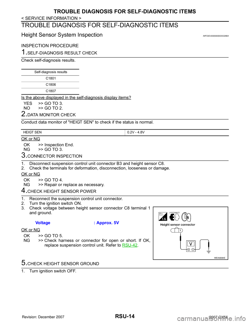
3. Check voltage between height sensor connector C8 terminal 1
and ground.
OK or NG
OK >> GO TO 5.
NG >> Check harness or connector for open or short. If OK,
replace suspension control unit. Refer to RSU-42
.
5.CHECK HEIGHT SENSOR GROUND
1. Turn ignition switch OFF.
Self-diagnosis results
C1801
C1806
C1807
HEIGT SEN 0.2V - 4.8V
Voltage : Approx. 5V
WEIA0084E
Page 2606 of 3061
RSU-16
< SERVICE INFORMATION >
TROUBLE DIAGNOSIS FOR SELF-DIAGNOSTIC ITEMS
The "COMPRESSOR" active test will remain ON until it is turned off using CONSULT-II. Allowing
the compressor to run for an extended period of time may cause damage to air suspension sys-
tem components due to excessive pressure in the air suspension system.
3. Return the rear load leveling air suspension system to normal operating mode.
4. Check self-diagnostic results.
Is code C1805 displayed again?
YES >> GO TO 3.
NO >> Inspection End.
3.CONNECTOR INSPECTION
1. Disconnect suspension control unit connector B3 and suspension air compressor C9.
2. Check the terminals for deformation, disconnection, looseness or damage.
OK or NG
OK >> If code C1805 was retrieved during self-diagnosis, GO TO 4. If code C1803 was retrieved during
self-diagnosis, GO TO 6.
NG >> Repair or replace as necessary.
4.AIR HOSE INSPECTION
Inspect for pinched or damaged air hoses between the suspension air reservoir and each load leveling rear air
suspension shock absorber.
OK or NG
OK >> GO TO 5.
NG >> Repair or replace as necessary.
5.EXHAUST VALVE SOLENOID INSPECTION
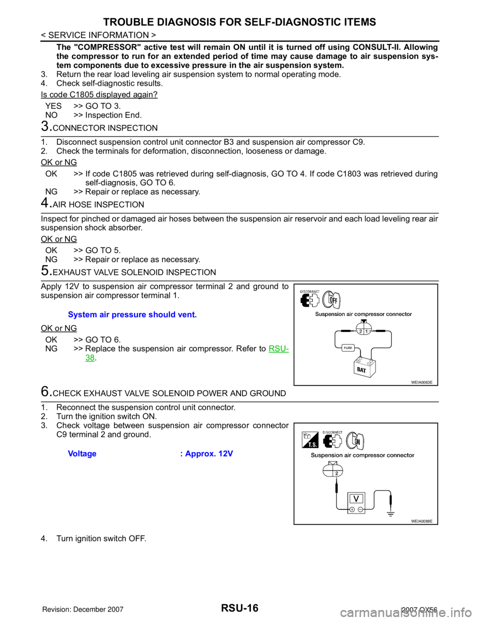
Apply 12V to suspension air compressor terminal 2 and ground to
suspension air compressor terminal 1.
OK or NG
OK >> GO TO 6.
NG >> Replace the suspension air compressor. Refer to RSU-
38.
6.CHECK EXHAUST VALVE SOLENOID POWER AND GROUND
1. Reconnect the suspension control unit connector.
2. Turn the ignition switch ON.
3. Check voltage between suspension air compressor connector
C9 terminal 2 and ground.
4. Turn ignition switch OFF.System air pressure should vent.
WEIA0063E
Voltage : Approx. 12V
WEIA0088E
Page 2608 of 3061
RSU-18
< SERVICE INFORMATION >
TROUBLE DIAGNOSIS FOR SELF-DIAGNOSTIC ITEMS
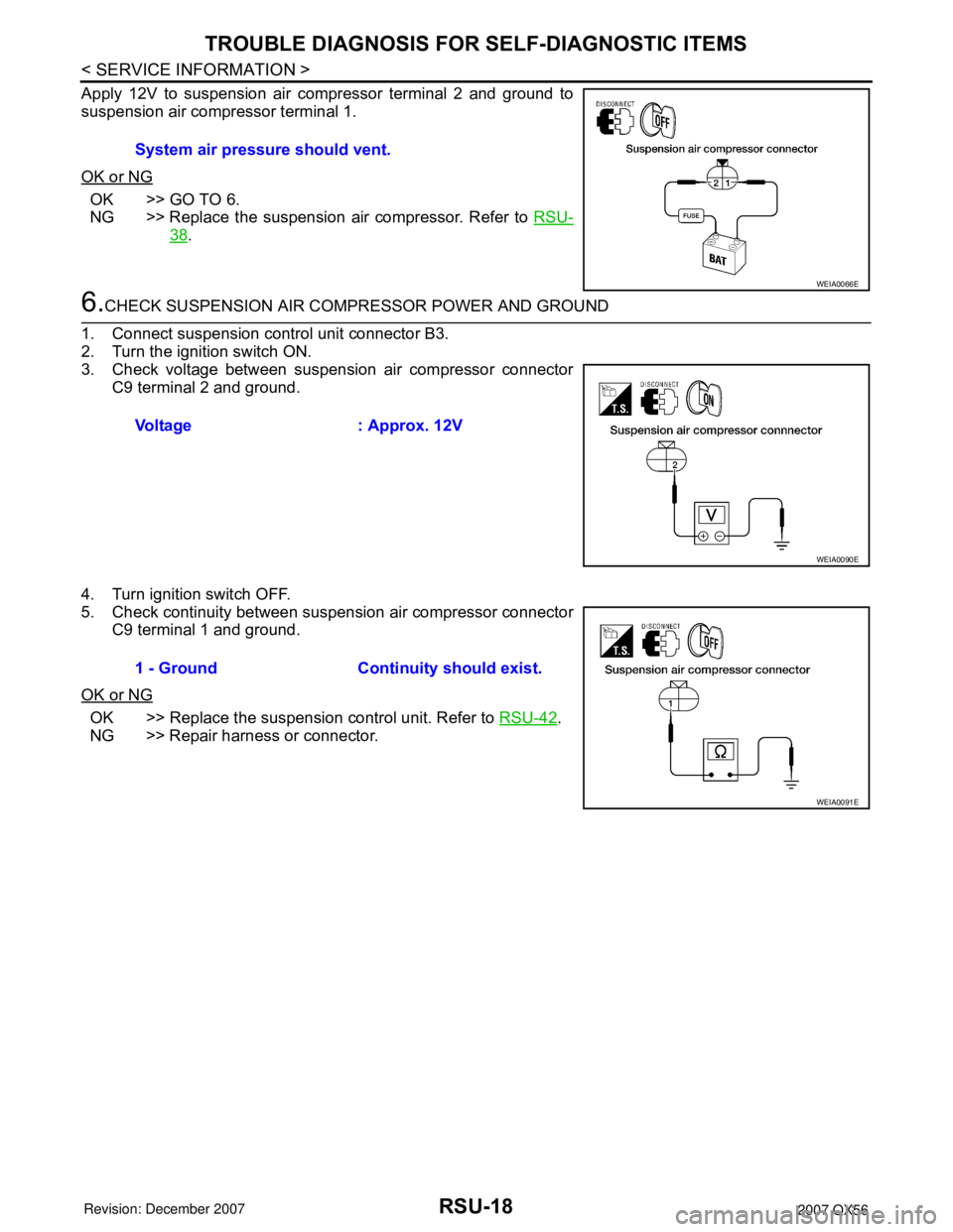
Apply 12V to suspension air compressor terminal 2 and ground to
suspension air compressor terminal 1.
OK or NG
OK >> GO TO 6.
NG >> Replace the suspension air compressor. Refer to RSU-
38.
6.CHECK SUSPENSION AIR COMPRESSOR POWER AND GROUND
1. Connect suspension control unit connector B3.
2. Turn the ignition switch ON.
3. Check voltage between suspension air compressor connector
C9 terminal 2 and ground.
4. Turn ignition switch OFF.
5. Check continuity between suspension air compressor connector
C9 terminal 1 and ground.
OK or NG
OK >> Replace the suspension control unit. Refer to RSU-42.
NG >> Repair harness or connector.System air pressure should vent.
WEIA0066E
Voltage : Approx. 12V
WEIA0090E
1 - Ground Continuity should exist.
WEIA0091E
Page 2609 of 3061
TROUBLE DIAGNOSES FOR SYMPTOMS
RSU-19
< SERVICE INFORMATION >
C
D
F
G
H
I
J
K
L
MA
B
RSU
N
O
P
TROUBLE DIAGNOSES FOR SYMPTOMS
Load Leveling Rear Air Suspension System Does Not OperateINFOID:0000000003532667
1.CHECK WARNING LAMP ACTIVATION
Make sure warning lamp remains off while driving.
OK or NG
OK >> GO TO 2.
NG >> Carry out self-diagnosis. Refer to RSU-11, "
CONSULT-II Function (AIR LEVELIZER)" .
2.CHECK FUSES AND FUSIBLE LINK
Check that the following fuses and fusible link are not blown.
OK or NG
OK >> GO TO 3.
NG >> If fuse or fusible link is blown, be sure to eliminate cause of malfunction before installing new fuse
or fusible link.
3.CHECK SUSPENSION CONTROL UNIT POWER AND GROUND
1. Turn the ignition switch ON.
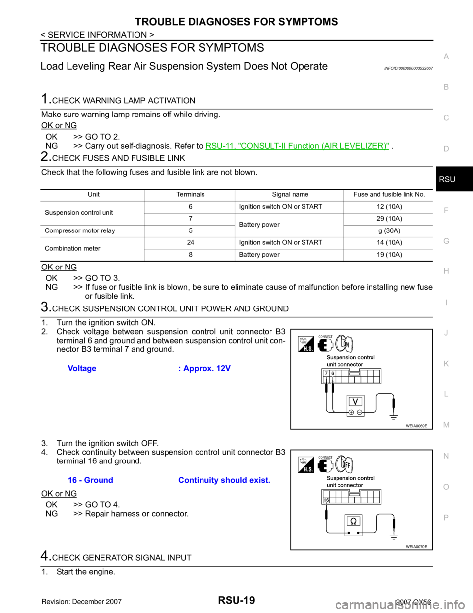
2. Check voltage between suspension control unit connector B3
terminal 6 and ground and between suspension control unit con-
nector B3 terminal 7 and ground.
3. Turn the ignition switch OFF.
4. Check continuity between suspension control unit connector B3
terminal 16 and ground.
OK or NG
OK >> GO TO 4.
NG >> Repair harness or connector.
4.CHECK GENERATOR SIGNAL INPUT
1. Start the engine.
Unit Terminals Signal name Fuse and fusible link No.
Suspension control unit6 Ignition switch ON or START 12 (10A)
7
Battery power29 (10A)
Compressor motor relay 5 g (30A)
Combination meter24 Ignition switch ON or START 14 (10A)
8 Battery power 19 (10A)
Voltage : Approx. 12V
WEIA0069E
16 - Ground Continuity should exist.
WEIA0070E