Page 4241 of 4647

SE-42
AUTOMATIC DRIVE POSITIONER
Revision: 2007 April2007 M35/M45
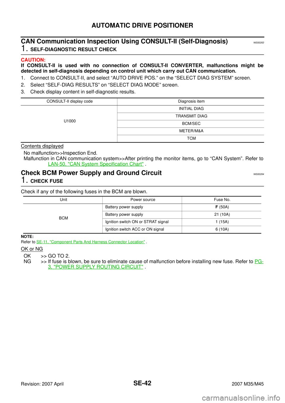
CAN Communication Inspection Using CONSULT-II (Self-Diagnosis)NIS00263
1. SELF-DIAGNOSTIC RESULT CHECK
CAUTION:
If CONSULT-II is used with no connection of CONSULT-II CONVERTER, malfunctions might be
detected in self-diagnosis depending on control unit which carry out CAN communication.
1. Connect to CONSULT-II, and select “AUTO DRIVE POS.” on the “SELECT DIAG SYSTEM” screen.
2. Select “SELF-DIAG RESULTS” on “SELECT DIAG MODE” screen.
3. Check display content in self-diagnostic results.
Contents displayed
No malfunction>>Inspection End.
Malfunction in CAN communication system>>After printing the monitor items, go to “CAN System”. Refer to
LAN-50, "
CAN System Specification Chart" .
Check BCM Power Supply and Ground CircuitNIS00264
1. CHECK FUSE
Check if any of the following fuses in the BCM are blown.
NOTE:
Refer to SE-11, "
Component Parts And Harness Connector Location" .
OK or NG
OK >> GO TO 2.
NG >> If fuse is blown, be sure to eliminate cause of malfunction before installing new fuse. Refer to PG-
3, "POWER SUPPLY ROUTING CIRCUIT" .
CONSULT-II display code Diagnosis item
U1000INITIAL DIAG
TRANSMIT DIAG
BCM/SEC
METER/M&A
TCM
Unit Power source Fuse No.
BCMBattery power supplyF (50A)
Battery power supply 21 (10A)
Ignition switch ON or STRAT signal 1 (15A)
Ignition switch ACC or ON signal 6 (10A)
Page 4254 of 4647
AUTOMATIC DRIVE POSITIONER
SE-55
C
D
E
F
G
H
J
K
L
MA
B
SE
Revision: 2007 April2007 M35/M45
Check Reclining Sensor Circuit NIS0026E
1. CHECK FUNCTION
With CONSULT-II
Check operation with “RECLN PULSE” on the DATA MONITOR to make sure the pulse changes.
Without CONSULT-II
1. Turn ignition switch OFF.
2. Check signal between driver seat control unit connector and ground, with oscilloscope.
OK or NG
OK >> Reclining sensor circuit is OK.
NG >> GO TO 2.
Monitor item [OPERATION or UNIT] Contents
RECLN PULSE —The seat reclining position (pulse) judged
from the reclining sensor is displayed
PIIA4558E
Driver seat
control unit
connectorTerminals
ConditionSignal
(Reference value)
(+) (–)
B204 9 GroundReclining
motor
operation
PIIB6150EPIIB2807E
Page 4258 of 4647
AUTOMATIC DRIVE POSITIONER
SE-59
C
D
E
F
G
H
J
K
L
MA
B
SE
Revision: 2007 April2007 M35/M45
Check Rear Lifting Sensor Circuit NIS0026G
1. CHECK FUNCTION
With CONSULT-II
Check operation with “LIFT RR PULSE” on the DATA MONITOR to make sure pulse changes.
Without CONSULT-II
1. Turn ignition switch OFF.
2. Check signal between driver seat control unit connector and ground, with oscilloscope.
OK or NG
OK >> Rear lifting sensor circuit is OK.
NG >> GO TO 2.
Monitor item [OPERATION or UNIT]
LIFT RR PULSE —The rear lifting position (pulse) judged from
the lifting sensor (rear) is displayed.
PIIA4558E
Driver seat
control unit
connectorTe r m i n a l s
ConditionSignal
(Reference value)
(+) (–)
B204 10 GroundRear
lifting
motor
operation
PIIB6156EPIIA3278E
Page 4260 of 4647
AUTOMATIC DRIVE POSITIONER
SE-61
C
D
E
F
G
H
J
K
L
MA
B
SE
Revision: 2007 April2007 M35/M45
Check Telescopic Sensor Circuit NIS0026H
1. CHECK FUNCTION
With CONSULT-II
Operate the telescopic switch with “TELESCO SEN” on the DATA MONITOR to make sure the voltage
changes.
Without CONSULT-II
1. Turn ignition switch OFF.
2. Check voltage between automatic drive positioner control unit connector and ground.
OK or NG
OK >> Telescopic sensor circuit is OK.
NG >> GO TO 2.
Monitor item
[OPERATION or UNIT]Contents
TELESCO
SEN“V”The telescoping position (voltage) judged from the tele-
scoping sensor signal is displayed.
PIIA0295E
Automatic
drive posi-
tioner con-
nectorTerminals
ConditionVoltage (V)
(Approx.)
(+) (–)
M6 23 GroundTelescopic
top position4.6
Telescopic
bottom position0.4
PIIB6159E
Page 4262 of 4647
AUTOMATIC DRIVE POSITIONER
SE-63
C
D
E
F
G
H
J
K
L
MA
B
SE
Revision: 2007 April2007 M35/M45
Check Tilt Sensor Circuit NIS0026I
1. CHECK TILT SENSOR
With CONSULT-II
With “TILT SEN” on the DATA MONITOR, operate the tilt switch to make sure voltage changes.
Without CONSULT-II
1. Turn ignition switch OFF.
2. Check voltage between automatic drive positioner control unit connector and ground.
OK or NG
OK >> Tilt sensor circuit is OK.
NG >> GO TO 2.
Monitor item
[OPERATION or UNIT]Contents
TILT SEN “V”The tilt position (voltage) judged from the tilt sensor sig-
nal is displayed.
PIIA0295E
Automatic
drive posi-
tioner con-
trol unit
connectorTerminals
ConditionVoltage (V)
(Approx.)
(+) (–)
M6 7 GroundTilt top position 1
Tilt bottom position 3.8
PIIB6161E
Page 4264 of 4647
AUTOMATIC DRIVE POSITIONER
SE-65
C
D
E
F
G
H
J
K
L
MA
B
SE
Revision: 2007 April2007 M35/M45
2. CHECK DOOR MIRROR LH SENSOR
With CONSULT–II
Check that “VOLTAGE” is displayed on “MIR/SE LH R–L, MIR/SE LH U–D” in the DATA MONITOR.
Without CONSULT–II
1. Turn ignition switch to ACC.
2. Check voltage between automatic drive positioner control unit connector and ground.
OK or NG
OK >> Mirror sensor LH circuit is OK.
NG >> GO TO 3.
Monitor item
[OPERATION or UNIT]Contents
MIR/
SEN LH R–L“V”Voltage output from door mirror LH sensor (LH/
RH) is displayed.
MIR/
SEN LH U–D“V”Voltage output from door mirror LH sensor (UP/
DOWN) is displayed.
PIIB6495E
Automatic
drive posi-
tioner con-
trol unit
connectorTe r m i n a l s
ConditionVoltage (V)
(Approx.)
(+) (–)
M622
GroundMirror motor is
operated LEFT or
RIGHTChanges between
3.5 (close to right edge) –
0.5 (close to left edge)
6Mirror motor is
operated UP or
DOWN Changes between
4.2 (close to peak) – 0.5
(close to valley)
PIIB6163E
Page 4266 of 4647

AUTOMATIC DRIVE POSITIONER
SE-67
C
D
E
F
G
H
J
K
L
MA
B
SE
Revision: 2007 April2007 M35/M45
Check Door Mirror Sensor RH CircuitNIS0026K
1. CHECK DOOR MIRROR FUNCTION
Check the following items.
Operation malfunction in memory operation.
NOTE:
If a door mirror face position is set to an implausible angle, the set position may not be reproduced.
OK or NG
OK >> GO TO 2.
NG >> Repair or replace the malfunctioning parts, and check the symptom again.
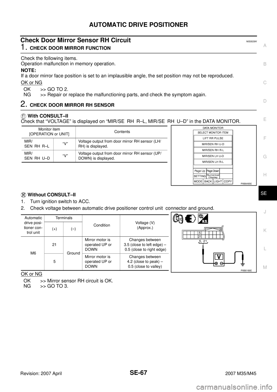
2. CHECK DOOR MIRROR RH SENSOR
With CONSULT–II
Check that “VOLTAGE” is displayed on “MIR/SE RH R–L, MIR/SE RH U–D” in the DATA MONITOR.
Without CONSULT–II
1. Turn ignition switch to ACC.
2. Check voltage between automatic drive positioner control unit connector and ground.
OK or NG
OK >> Mirror sensor RH circuit is OK.
NG >> GO TO 3.
Monitor item
[OPERATION or UNIT]Contents
MIR/
SEN RH R–L“V”Voltage output from door mirror RH sensor (LH/
RH) is displayed.
MIR/
SEN RH U–D“V”Voltage output from door mirror RH sensor (UP/
DOWN) is displayed.
PIIB6495E
Automatic
drive posi-
tioner con-
trol unitTerminals
ConditionVoltage (V)
(Approx.)
(+) (–)
M621
GroundMirror motor is
operated UP or
DOWNChanges between
3.5 (close to left edge) –
0.5 (close to right edge)
5Mirror motor is
operated UP or
DOWN Changes between
4.2 (close to peak) –
0.5 (close to valley)
PIIB6166E
Page 4268 of 4647
AUTOMATIC DRIVE POSITIONER
SE-69
C
D
E
F
G
H
J
K
L
MA
B
SE
Revision: 2007 April2007 M35/M45
Check Sliding Switch Circuit NIS0026L
1. CHECK FUNCTION
With CONSULT-II
With “SLIDE SW-FR, SLIDE SW-RR” on the DATA MONITOR, oper-
ate the sliding switch to check ON/OFF operation.
Without CONSULT-II
1. Turn ignition switch OFF.
2. Check voltage between driver seat control unit connector and
ground.
OK or NG
OK >> Sliding switch circuit is OK.
NG >> GO TO 2.
Monitor item [OPER-
ATION or UNIT]Contents
SLIDE SW–
FR"ON/
OFF"ON / OFF status judged from the sliding switch (FR) sig-
nal is displayed.
SLIDE SW–
RR"ON/
OFF"ON / OFF status judged from the sliding switch (RR) sig-
nal is displayed.
PIIA0313E
Driver seat
control unit
connectorTe r m i n a l
ConditionVoltage (V)
(Approx.)
(+) (–)
B20411
GroundSliding switch ON
(BACKWARD
operation)0
Other than above Battery voltage
26Sliding switch ON
(FORWARD
operation)0
Other than above Battery voltage
PIIB6168E