Page 4270 of 4647
AUTOMATIC DRIVE POSITIONER
SE-71
C
D
E
F
G
H
J
K
L
MA
B
SE
Revision: 2007 April2007 M35/M45
Check Reclining Switch Circuit NIS0026M
1. CHECK FUNCTION
With CONSULT-II
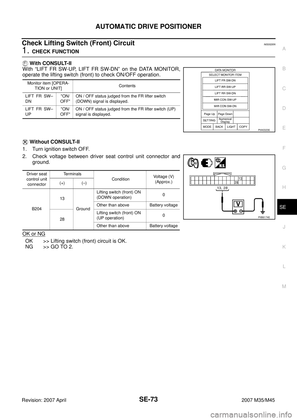
With “RECLN SW-FR, RECLN SW-RR” on the DATA MONITOR,
operate the reclining switch to check ON/OFF operation.
Without CONSULT-II
1. Turn ignition switch OFF.
2. Check voltage between driver seat control unit connector and
ground.
OK or NG
OK >> Reclining switch circuit is OK.
NG >> GO TO 2.
Monitor item [OPERA-
TION or UNIT]Contents
RECLN SW
–FR“ON/
OFF”ON/OFF status judged from the reclining switch (FR)
signal is displayed.
RECLIN S
W–RR“ON/
OFF”ON/OFF status judged from the reclining switch (RR)
signal is displayed.
PIIA0313E
Driver seat
control unitTerminals
ConditionVoltage (V)
(Approx.)
(+) (–)
B20412
GroundReclining switch ON
(BACKWARD
operation)0
Other than above Battery voltage
27Reclining switch ON
(FORWARD
operation)0
Other than above Battery voltage
PIIB6171E
Page 4272 of 4647

AUTOMATIC DRIVE POSITIONER
SE-73
C
D
E
F
G
H
J
K
L
MA
B
SE
Revision: 2007 April2007 M35/M45
Check Lifting Switch (Front) Circuit NIS0026N
1. CHECK FUNCTION
With CONSULT-II
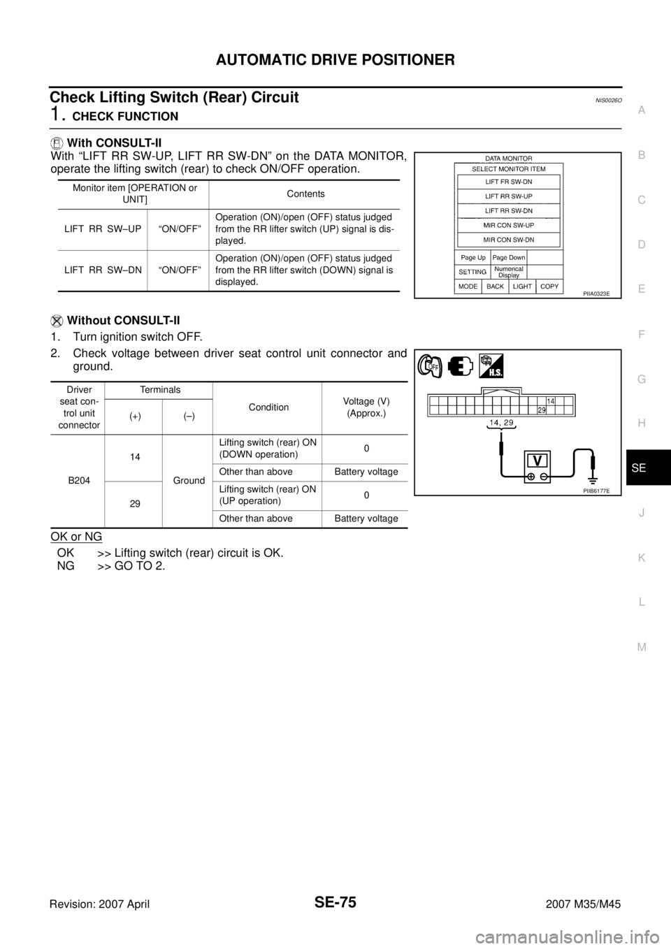
With “LIFT FR SW-UP, LIFT FR SW-DN” on the DATA MONITOR,
operate the lifting switch (front) to check ON/OFF operation.
Without CONSULT-II
1. Turn ignition switch OFF.
2. Check voltage between driver seat control unit connector and
ground.
OK or NG
OK >> Lifting switch (front) circuit is OK.
NG >> GO TO 2.
Monitor item [OPERA-
TION or UNIT]Contents
LIFT FR SW–
DN"ON/
OFF"ON / OFF status judged from the FR lifter switch
(DOWN) signal is displayed.
LIFT FR SW–
UP"ON/
OFF"ON / OFF status judged from the FR lifter switch (UP)
signal is displayed.
PIIA0323E
Driver seat
control unit
connectorTerminals
ConditionVoltage (V)
(Approx.)
(+) (–)
B20413
GroundLifting switch (front) ON
(DOWN operation)0
Other than above Battery voltage
28Lifting switch (front) ON
(UP operation)0
Other than above Battery voltage
PIIB6174E
Page 4274 of 4647

AUTOMATIC DRIVE POSITIONER
SE-75
C
D
E
F
G
H
J
K
L
MA
B
SE
Revision: 2007 April2007 M35/M45
Check Lifting Switch (Rear) Circuit NIS0026O
1. CHECK FUNCTION
With CONSULT-II
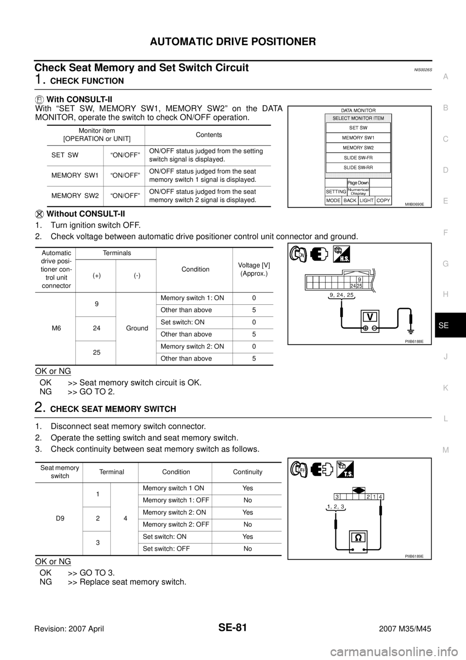
With “LIFT RR SW-UP, LIFT RR SW-DN” on the DATA MONITOR,
operate the lifting switch (rear) to check ON/OFF operation.
Without CONSULT-II
1. Turn ignition switch OFF.
2. Check voltage between driver seat control unit connector and
ground.
OK or NG
OK >> Lifting switch (rear) circuit is OK.
NG >> GO TO 2.
Monitor item [OPERATION or
UNIT]Contents
LIFT RR SW–UP “ON/OFF”Operation (ON)/open (OFF) status judged
from the RR lifter switch (UP) signal is dis-
played.
LIFT RR SW–DN “ON/OFF”Operation (ON)/open (OFF) status judged
from the RR lifter switch (DOWN) signal is
displayed.
PIIA0323E
Driver
seat con-
trol unit
connectorTerminals
ConditionVoltage (V)
(Approx.)
(+) (–)
B20414
GroundLifting switch (rear) ON
(DOWN operation)0
Other than above Battery voltage
29Lifting switch (rear) ON
(UP operation)0
Other than above Battery voltage
PIIB6177E
Page 4276 of 4647
AUTOMATIC DRIVE POSITIONER
SE-77
C
D
E
F
G
H
J
K
L
MA
B
SE
Revision: 2007 April2007 M35/M45
Check Telescopic Switch Circuit NIS0026Q
1. CHECK FUNCTION
With CONSULT-II
With “TELESCO SW-FR, TELESCO SW-RR” on the DATA MONITOR, operate the ADP steering switch to
check ON/OFF operation.
Without CONSULT-II
1. Turn ignition switch OFF.
2. Check voltage between automatic drive positioner control unit connector and ground.
OK or NG
OK >> Telescopic switch circuit is OK.
NG >> GO TO 2.
Monitor item
[OPERATION or UNIT]Contents
TELESCO SW-FR “ON/OFF”(ON/OFF) status judged from the telescoping
switch (FR) signal is displayed.
TELESCO SW-RR “ON/OFF” (ON/OFF) status judged from the telescoping
switch (RR) signal is displayed.
PIIA0315E
Automatic
drive posi-
tioner con-
trol unit
connectorTerminals
Telescopic switch conditionVoltage (V)
(Approx.)
(+) (–)
M611
GroundFORWARD 0
Other than above 5
27BACKWARD 0
Other than above 5
PIIB6181E
Page 4278 of 4647
AUTOMATIC DRIVE POSITIONER
SE-79
C
D
E
F
G
H
J
K
L
MA
B
SE
Revision: 2007 April2007 M35/M45
Check Tilt Switch Circuit NIS0026R
1. CHECK FUNCTION
With CONSULT-II
With “TILT SW-UP,TILT SW-DOWN” on the DATA MONITOR, operate the ADP steering switch to check ON/
OFF operation.
Without CONSULT-II
1. Turn ignition switch OFF.
2. Check voltage between automatic drive positioner control unit connector and ground.
OK or NG
OK >> Tilt switch circuit is OK.
NG >> GO TO 2.
Monitor item
[OPERATION or UNIT]Contents
TILT SW-UP “ON/OFF” (ON/OFF) status judged from the tilt switch
(UP) signal is displayed.
TILT SW-DOWN “ON/OFF”(ON/OFF) status judged from the tilt switch
(DOWN) signal is displayed.
PIIA0315E
Automatic
drive posi-
tioner con-
trol unit
connectorTerminals
Tilt switch conditionVoltage (V)
(Approx.)
(+) (–)
M61
GroundUP 0
Other than above 5
17DOWN 0
Other than above 5
PIIB6185E
Page 4280 of 4647

AUTOMATIC DRIVE POSITIONER
SE-81
C
D
E
F
G
H
J
K
L
MA
B
SE
Revision: 2007 April2007 M35/M45
Check Seat Memory and Set Switch Circuit NIS0026S
1. CHECK FUNCTION
With CONSULT-II
With “SET SW, MEMORY SW1, MEMORY SW2” on the DATA
MONITOR, operate the switch to check ON/OFF operation.
Without CONSULT-II
1. Turn ignition switch OFF.
2. Check voltage between automatic drive positioner control unit connector and ground.
OK or NG
OK >> Seat memory switch circuit is OK.
NG >> GO TO 2.
2. CHECK SEAT MEMORY SWITCH
1. Disconnect seat memory switch connector.
2. Operate the setting switch and seat memory switch.
3. Check continuity between seat memory switch as follows.
OK or NG
OK >> GO TO 3.
NG >> Replace seat memory switch.
Monitor item
[OPERATION or UNIT]Contents
SET SW “ON/OFF”ON/OFF status judged from the setting
switch signal is displayed.
MEMORY SW1 “ON/OFF”ON/OFF status judged from the seat
memory switch 1 signal is displayed.
MEMORY SW2 “ON/OFF”ON/OFF status judged from the seat
memory switch 2 signal is displayed.
Automatic
drive posi-
tioner con-
trol unit
connectorTerminals
ConditionVoltage [V]
(Approx.)
(+) (-)
M69
GroundMemory switch 1: ON 0
Other than above 5
24Set switch: ON 0
Other than above 5
25Memory switch 2: ON 0
Other than above 5
MIIB0690E
PIIB6188E
Seat memory
switchTerminal Condition Continuity
D91
4Memory switch 1 ON Yes
Memory switch 1: OFF No
2Memory switch 2: ON Yes
Memory switch 2: OFF No
3Set switch: ON Yes
Set switch: OFF No
PIIB6189E
Page 4285 of 4647

SE-86
AUTOMATIC DRIVE POSITIONER
Revision: 2007 April2007 M35/M45
Check A/T Device (Detention Switch) Circuit NIS0026V
1. CHECK FUNCTION
With CONSULT-II
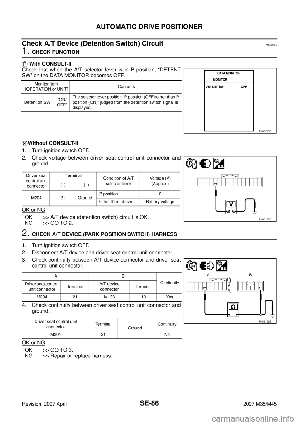
Check that when the A/T selector lever is in P position, “DETENT
SW” on the DATA MONITOR becomes OFF.
Without CONSULT-II
1. Turn ignition switch OFF.
2. Check voltage between driver seat control unit connector and
ground.
OK or NG
OK >> A/T device (detention switch) circuit is OK.
NG >> GO TO 2.
2. CHECK A/T DEVICE (PARK POSITION SWITCH) HARNESS
1. Turn ignition switch OFF.
2. Disconnect A/T device and driver seat control unit connector.
3. Check continuity between A/T device connector and driver seat
control unit connector.
4. Check continuity between driver seat control unit connector and
ground.
OK or NG
OK >> GO TO 3.
NG >> Repair or replace harness.
Monitor item
[OPERATION or UNIT]Contents
Detention SW“ON/
OFF”The selector lever position “P position (OFF)/other than P
position (ON)” judged from the detention switch signal is
displayed.
PIIB6293E
Driver seat
control unit
connectorTerminal
Condition of A/T
selector leverVoltage (V)
(Approx.)
(+) (–)
M204 21 GroundP position 0
Other than above Battery voltage
PIIB6198E
AB
Continuity
Driver seat control
unit connectorTe r m i n a lA/T device
connectorTerminal
M204 21 M133 10 Yes
Driver seat control unit
connectorTerminal
GroundContinuity
M204 21 No
PIIB6199E
Page 4388 of 4647

SUPPLEMENTAL RESTRAINT SYSTEM (SRS)
SRS-7
C
D
E
F
G
I
J
K
L
MA
B
SRS
Revision: 2007 April2007 M35/M45
Occupant Classification System (OCS) NHS0008W
The occupant classification system identifies different size occupants, out of position occupants, and detects if
child seat is present in the front passenger seat. The occupant classification system receives inputs from the
occupant classification sensor (located inside the passenger seat cushion assembly) and belt tension sensor
(part of the passenger front seat belt assembly and located at the belt anchor location). Depending on classifi-
cation of passenger, the occupant classification system sends a signal to the diagnosis sensor unit. The diag-
nosis sensor unit uses this signal to determine full, partial, or non deployment of passenger front air bag in the
event of a collision. Depending on the signal received, the diagnosis sensor unit can disable the passenger
front air bag completely.
NOTE:
In case of customer concern, CONSULT-ll can be used to confirm the passenger air bag status (readiness).
Passenger Air Bag Status Condition NHS0008X
NOTE:
Passenger does not meet Ocuupant Classification System specifications for passenger air bag activation.
Component Parts of Occupant Classification System NHS0008Y
Front Passenger Seat
(Condition)PASS AIR BAG OFF Indicator
(Status)Passenger Air Bag Status
(Readiness)CONSULT-ll Display
Seat occupied OFF Active (enabled) ON
seat occupiedNOTE ON Deactivated (disabled) OFF
Seat empty OFF Deactivated (disabled) OFF
PHIA1177E
1.Occupant classification system con-
trol unit2. Belt tension sensor 3. Seat pressure sensor
4. Bladder 5.Front passenger air bag OFF indica-
tor (Cutoff telltaile)