Page 3829 of 4647

MA-30
CHASSIS AND BODY MAINTENANCE
Revision: 2007 April2007 M35/M45
NOTE:
A/T fluid level will be greatly affected by temperature as shown in figure. Therefore, be certain to
perform operation while checking data with CONSULT-II.
a. Connect CONSULT-II to data link connector. Refer to AT- 9 2 , "
CONSULT-II SETTING PROCEDURE" .
b. Select “MAIN SIGNALS” in “DATA MONITOR” mode for “A/T” with CONSULT-II.
c. Read out the value of “ATF TEMP 1”.
7. Re-check A/T fluid level at A/T fluid temperatures of approximately 65°C (149°F) using “HOT” range on A/
T fluid level gauge.
CAUTION:
�When wiping away the A/T fluid level gauge, always use lint-free paper, not a cloth one.
�To check A/T fluid level, insert the A/T fluid level gauge
until the cap contacts the end of the A/T fluid charging
pipe, with the A/T fluid level gauge reversed from the nor-
mal attachment conditions as shown.
8. Check A/T fluid condition.
�If ATF is very dark or smells burned, check operation of A/T.
Flush cooling system after repair of A/T.
�If A/T fluid contains frictional material (clutches, bands, etc.),
replace radiator and flush cooler line using cleaning solvent
and compressed air after repair of A/T. Refer to CO-14,
"RADIATOR" (for VQ35DE engine), CO-43, "RADIATOR"
(for VK45DE engine) and AT- 1 4 , "A/T Fluid Cooler Cleaning" .
9. Install the removed A/T fluid level gauge in the A/T fluid charging
pipe.
10. Tighten level gauge bolt.
Level gauge bolt
: 5.1 N·m (0.52 kg-m, 45 in-lb)
SLIA0016E
SCIA2899E
SCIA4896E
Page 3835 of 4647
MA-36
CHASSIS AND BODY MAINTENANCE
Revision: 2007 April2007 M35/M45
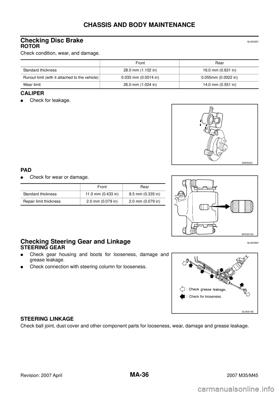
Checking Disc BrakeNLS0008C
ROTOR
Check condition, wear, and damage.
CALIPER
�Check for leakage.
PA D
�Check for wear or damage.
Checking Steering Gear and LinkageNLS0008D
STEERING GEAR
�Check gear housing and boots for looseness, damage and
grease leakage.
�Check connection with steering column for looseness.
STEERING LINKAGE
Check ball joint, dust cover and other component parts for looseness, wear, damage and grease leakage.
Front Rear
Standard thickness 28.0 mm (1.102 in) 16.0 mm (0.631 in)
Runout limit (with it attached to the vehicle) 0.035 mm (0.0014 in) 0.055mm (0.0022 in)
Wear limit 26.0 mm (1.024 in) 14.0 mm (0.551 in)
SMA922A
Front Rear
Standard thickness 11.0 mm (0.433 in) 8.5 mm (0.335 in)
Repair limit thickness 2.0 mm (0.079 in) 2.0 mm (0.079 in)
BRA0010D
SLIA0014E
Page 3849 of 4647

PB-8
PARKING BRAKE SHOE
Revision: 2007 April2007 M35/M45
–Anti-rattle pin for excessive wear and corrosion.
–Return spring for sagging.
�Make sure that adjuster moves smoothly.
�Visually check the inside of drum for excessive wear, cracks, and damage. Check the inside of drum using
a pair of vernier calipers.
�Replace with new part if the above part is malfunction.
INSTALLATION
Note the following, and install in the reverse order of removal.
�Refer to PB-6, "Components" and apply PBC (Poly Butyl Cupry-
sil) grease or silicone-based grease to the specified points dur-
ing assembly.
�Assemble adjusters so that threaded part is expanded when
rotating it in the direction shown by arrow.
�Shorten adjuster by rotating it.
�Check shoe sliding surface and drum inner surface for grease.
Wipe it off if it adhere on the surfaces.
�Perform break-in operation as follows after replacing brake
shoes or disc rotors, or if brakes do not function well.
1. Adjust parking brake pedal stroke to the specified amount. Refer
to PB-3, "
ADJUSTMENT" .
2. Perform parking brake break-in (drag run) operation by driving vehicle under the following conditions:
3. Check parking brake pedal stroke of parking brake. Adjust again if it is outside the standard.Drive forward
�Vehicle speed: Approx. 40 km/h (25 MPH) set (constant and forward)
�Parking brake operating force: Approx. 400 N (40 kg, 89.9 lb) set constant
�Time: Approx. 10 sec.
SFIA2426E
Page 3888 of 4647

PG-37
C
D
E
F
G
H
I
J
L
MA
B
PG
Revision: 2007 April2007 M35/M45
Terminals and Reference Value for PDUNKS004EH
Work FlowNKS004EI
1. Check the symptom and customers reque")
PDU (POWER DISTRIBUTION UNIT)
PG-37
C
D
E
F
G
H
I
J
L
MA
B
PG
Revision: 2007 April2007 M35/M45
Terminals and Reference Value for PDUNKS004EH
Work FlowNKS004EI
1. Check the symptom and customer's requests.
2. Understand outline of system. Refer to PG-32, "
System Description" .
3. Confirm that Intelligent Key system operates normally.
Refer to BL-24, "
POWER DOOR LOCK SYSTEM" .
4. Repair or replace any malfunctioning parts.
Refer to PG-38, "
Trouble Diagnosis Symptom Chart" .
5. INSPECTION END
57 L Power source (Fuse) Input LOCK — Battery voltage
72 B Ground — — — 0 Te r m i -
nalWire
ColorItemSignal
Input/
OutputCondition
Voltage (V)
Approx. Ignition
Switch
PositionOperation or Conditions
Termi-
nalWire
ColorItemSignal
Input/
OutputCondition
Voltage (V)
Approx. Ignition
Switch
PositionOperation or Conditions
1 P PDU wake up signal Output LOCKPush-button ignition switch is in LOCK
state, 30 seconds after all doors closeBattery voltage
Other than above 0
4 BR Ignition signal 1 OutputLOCK — Battery voltage
ACC — Battery voltage
ON — 0
5 W Ignition signal 2 OutputLOCK — Battery voltage
ACC — Battery voltage
ON — 0
8 SB ACC signal OutputLOCK — Battery voltage
ACC — 0
ON — 0
10 B Ground — — — 0
11 Y IPDM E/R status signal Input —Engine starting (During Cranking) 5
Other than above 2
12 R PDU feedback signal Input LOCKPush-button ignition switch is in LOCK
state, 30 seconds after all doors close1
Other than above 0
14 SB Power source (Fuse) Input LOCK — Battery voltage
15 L Power source (F/L) Input LOCK — Battery voltage
16 W ACC power output OutputLOCK — 0
ACC — Battery voltage
ON — Battery voltage
17 G Power source (Fuse) Input LOCK — Battery voltage
18 BR ON power output OutputLOCK — 0
ACC — 0
ON — Battery voltage
Page 3890 of 4647

PG-39
C
D
E
F
G
H
I
J
L
MA
B
PG
Revision: 2007 April2007 M35/M45
Check PDU Power Supply and Ground CircuitNKS004EL
1. CHECK POWER SUPPLY CIRCUIT
1. Turn ignition switch O")
PDU (POWER DISTRIBUTION UNIT)
PG-39
C
D
E
F
G
H
I
J
L
MA
B
PG
Revision: 2007 April2007 M35/M45
Check PDU Power Supply and Ground CircuitNKS004EL
1. CHECK POWER SUPPLY CIRCUIT
1. Turn ignition switch OFF.
2. Disconnect PDU connector.
3. Check voltage between PDU harness connector and ground.
OK or NG
OK >> GO TO 2.
NG >> Repair or replace PDU power supply circuit.
2. CHECK GROUND CIRCUIT
Check continuity between PDU harness connector and ground.
OK or NG
OK >> Power supply and ground circuits are OK.
NG >> Repair or replace the PDU ground circuit.
Check Push-Button Ignition Switch (Ignition Switch) SystemNKS004EM
1. CHECK PUSH-BUTTON IGNITION SWITCH
1. Turn ignition switch OFF.
2. Disconnect Intelligent Key unit connector.
3. Check continuity between Intelligent Key unit harness connector
and ground.
OK or NG
OK >> Push-button ignition switch system is OK.
NG >> GO TO 2.
PDU connectorTe r m i n a l
Voltage (V)
(Approx.)
(+) (-)
M3114
Ground Battery voltage 15
17
PIIB6115E
PDU connector Terminal Continuity
M30 10 Ground Yes
PIIB6116E
Intelligent
Key unit
connectorTerminal Condition Continuity
M32 39 GroundPush-button ignition
switch is pressedYe s
Push-button ignition
switch is releasedNo
PIIB6117E
Page 3891 of 4647

Revision: 2007 April2007 M35/M45
2. CHECK PUSH-BUTTON IGNITION SWITCH OPERATION
1. Turn ignition switch OFF.
2. Check continuity push-button ignition switch connect")
PG-40
PDU (POWER DISTRIBUTION UNIT)
Revision: 2007 April2007 M35/M45
2. CHECK PUSH-BUTTON IGNITION SWITCH OPERATION
1. Turn ignition switch OFF.
2. Check continuity push-button ignition switch connector.
OK or NG
OK >> GO TO 3.
NG >> Replace push-button ignition switch.
3. CHECK PUSH-BUTTON IGNITION SWITCH GROUND CIRCUIT SYSTEM
Check continuity between push-button ignition switch harness con-
nector and ground.
OK or NG
OK >> GO TO 4.
NG >> Repair or replace push-button ignition switch ground cir-
cuit.
4. CHECK PUSH-BUTTON IGNITION SWITCH CIRCUIT
1. Disconnect Intelligent Key unit connector.
2. Check continuity between Intelligent Key unit harness connector and push-button switch harness connec-
tor.
3. Check continuity between push-button ignition switch harness
connector and ground.
OK or NG
OK >> GO TO 5.
NG >> Repair or replace harness between Intelligent Key unit and ignition switch.
Push-button
ignition
switch con-
nectorTerminal Condition Continuity
M27 1 4Push-button ignition
switch is pressedYe s
Push-button ignition
switch is releasedNo
PIIB6118E
Push-button ignition
switch connectorTerminal Continuity
M27 1Ground part of
push-button
ignition switchYe s
PIIB6120E
AB
Continuity Push-button
ignition switch
connectorTe r m i n a lIntelligent Key
unit connectorTerminal
M27 4 M32 39 Yes
Push-button ignition
switch connectorTerminal Continuity
M27 4 Ground No
PIIB6119E
Page 3892 of 4647

PG-41
C
D
E
F
G
H
I
J
L
MA
B
PG
Revision: 2007 April2007 M35/M45
Check Push-Button Ignition Switch (Indicator Circuit) SystemNKS004EN
1. CHECK PUSH-BUTTON IGNITION SWITCH")
PDU (POWER DISTRIBUTION UNIT)
PG-41
C
D
E
F
G
H
I
J
L
MA
B
PG
Revision: 2007 April2007 M35/M45
Check Push-Button Ignition Switch (Indicator Circuit) SystemNKS004EN
1. CHECK PUSH-BUTTON IGNITION SWITCH INDICATOR SYSTEM
1. Turn ignition switch OFF.
2. Check voltage between Intelligent Key unit connector and
ground.
OK or NG
OK >> GO TO 2.
NG >> Repair or replace push-button ignition switch.
2. PUSH-BUTTON IGNITION SWITCH INDICATOR POWER SUPPLY SIGNAL
1. Turn ignition switch OFF.
2. Disconnect push-button ignition switch.
3. Check voltage between push-button ignition switch connector
and ground.
OK or NG
OK >> GO TO 3.
NG >> Repair or replace push-button ignition switch.
Intelligent
Key unit
connectorTerminal
Push-button ignition
switch conditionVoltage (V)
(Approx)
(+) (-)
M328
Ground part of
push-button
ignition switchLOCK position 0
Except LOCK position 1.2
9ACC position 0
Except ACC position 1.2
10ON position 0
Except ON position 1.2
PIIB6121E
Push-button ignition
switch connectorTerminal
Voltage (V)
(Approx)
(+) (-)
M27 8 Ground Battery voltage
PIIB6122E
Page 3893 of 4647

Revision: 2007 April2007 M35/M45
3. PUSH-BUTTON IGNITION SWITCH INDICATOR GROUND CIRCUIT
1. Disconnect Intelligent Key unit connector.
2. Check continuity between I")
PG-42
PDU (POWER DISTRIBUTION UNIT)
Revision: 2007 April2007 M35/M45
3. PUSH-BUTTON IGNITION SWITCH INDICATOR GROUND CIRCUIT
1. Disconnect Intelligent Key unit connector.
2. Check continuity between Intelligent Key unit connector and
push-button ignition switch connector.
3. Check continuity between push-button ignition switch connector.
OK or NG
OK >> Check harness condition.
NG >> Repair or replace harness.
PDU Communication Circuit System 1NKS004EO
1. CHECK PDU COMMUNICATION CIRCUIT 1
1. Turn ignition switch OFF.
2. Check voltage between Intelligent Key unit connector and
ground.
OK or NG
OK >> Check harness condition.
NG >> GO TO 2.
AB
Continuity
Intelligent Key
unit connectorTe r m i n a lPush-button
ignition switch
connectorTerminal
M328
M275
Ye s 96
10 7
Push-button ignition
switch connectorTerminal Continuity
M275
Ground No 6
7
PIIB6123E
Intelligent Key
unit connectorTerminal ConditionVoltage (V)
(Approx)
M3342 GroundDriver side door is opened
(PDU wake up mode)0
Push-button ignition switch is in
lock state, 30 seconds after all
doors are closed (PDU sleep
mode)Battery
voltage
45 GroundPush-button ignition switch is in
LOCK positionBattery
voltage
Push-button ignition switch is in
ACC position0
Push-button ignition switch is in
ON position0
PIIB6124E