Page 3577 of 4647

LT-126
AUTO LIGHT SYSTEM
Revision: 2007 April2007 M35/M45
Terminals and Reference Values for IPDM E/RNKS003Q6
How to Perform Trouble DiagnosesNKS003Q7
1. Confirm the symptom or customer complaint.
2. Understand operation description and function description. Refer to LT- 11 5 , "
System Description" .
3. Perform the Preliminary Check. Refer to LT- 1 2 7 , "
Preliminary Check" .
4. Check symptom and repair or replace the cause of malfunction. Refer to LT- 1 3 0 , "
Symptom Chart" .
5. Does the auto light system operate normally? If YES, GO TO 6. If NO, GO TO 4.
6. INSPECTION END.
Terminal
No.Wire
colorSignal nameMeasuring condition
Reference value
Ignition
switchOperation or condition
20 R Headlamp low (RH) ONLighting switch 2ND
positionOFF Approx. 0 V
ON Battery voltage
21 R/LParking, license plate,
and tail lampONLighting switch 1ST
positionOFF Approx. 0 V
ON Battery voltage
27 BR Headlamp high (RH) ONLighting switch HIGH
or PASSING positionOFF Approx. 0 V
ON Battery voltage
28 R/Y Headlamp high (LH) ONLighting switch HIGH
or PASSING positionOFF Approx. 0 V
ON Battery voltage
30 R/B Headlamp low (LH) ONLighting switch 2ND
positionOFF Approx. 0 V
ON Battery voltage
38 B Ground ON — Approx. 0 V
49 L CAN − H— — —
50 P CAN − L— — —
51 B Ground ON — Approx. 0 V
Page 3639 of 4647
LT-188
ACTIVE AFS
Revision: 2007 April2007 M35/M45
Auto Aiming Does Not Operate (Check Aiming Motor System Circuit)NKS003QV
1. CHECK AIMING MOTOR
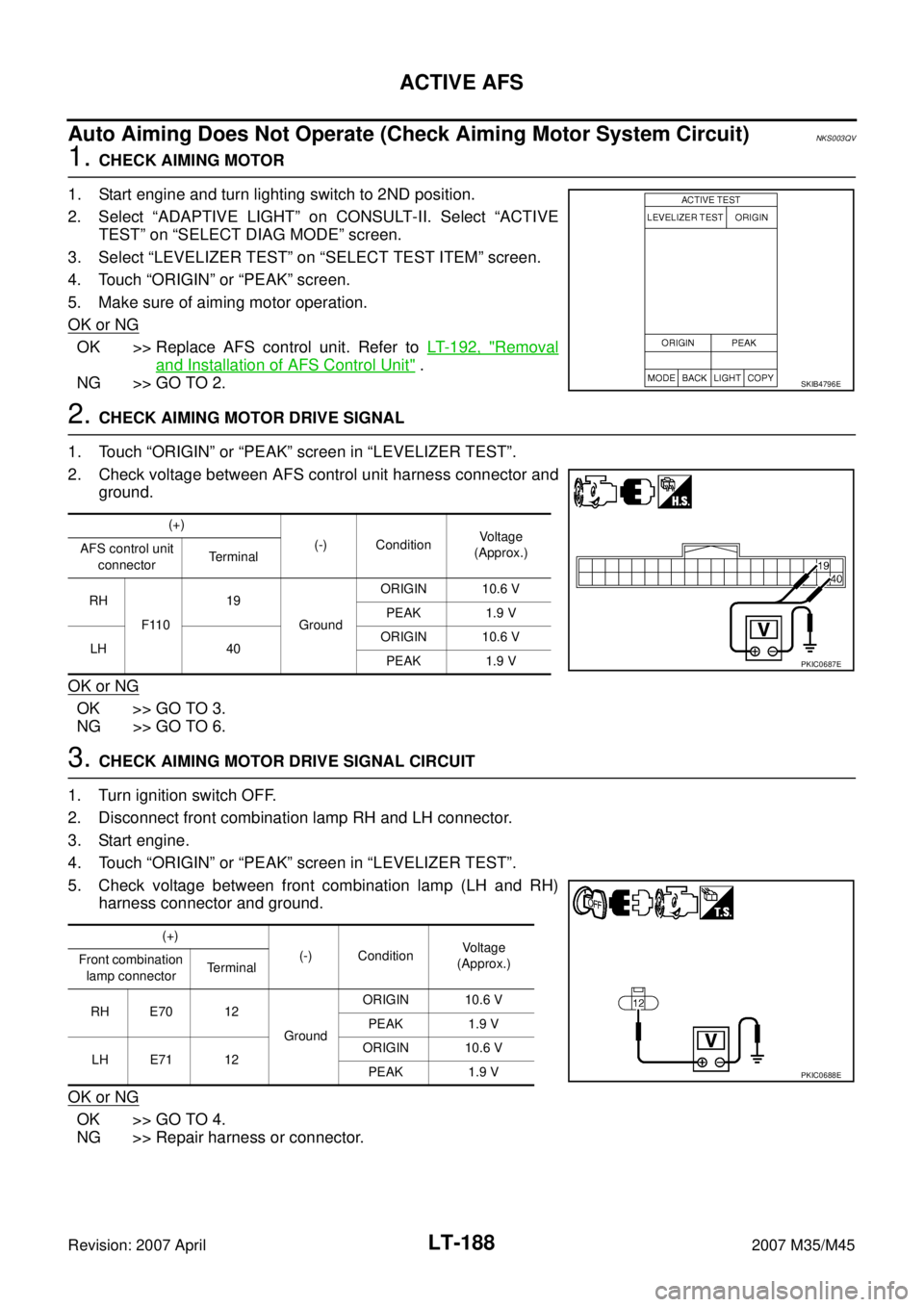
1. Start engine and turn lighting switch to 2ND position.
2. Select “ADAPTIVE LIGHT” on CONSULT-II. Select “ACTIVE
TEST” on “SELECT DIAG MODE” screen.
3. Select “LEVELIZER TEST” on “SELECT TEST ITEM” screen.
4. Touch “ORIGIN” or “PEAK” screen.
5. Make sure of aiming motor operation.
OK or NG
OK >> Replace AFS control unit. Refer to LT- 1 9 2 , "Removal
and Installation of AFS Control Unit" .
NG >> GO TO 2.
2. CHECK AIMING MOTOR DRIVE SIGNAL
1. Touch “ORIGIN” or “PEAK” screen in “LEVELIZER TEST”.
2. Check voltage between AFS control unit harness connector and
ground.
OK or NG
OK >> GO TO 3.
NG >> GO TO 6.
3. CHECK AIMING MOTOR DRIVE SIGNAL CIRCUIT
1. Turn ignition switch OFF.
2. Disconnect front combination lamp RH and LH connector.
3. Start engine.
4. Touch “ORIGIN” or “PEAK” screen in “LEVELIZER TEST”.
5. Check voltage between front combination lamp (LH and RH)
harness connector and ground.
OK or NG
OK >> GO TO 4.
NG >> Repair harness or connector.
SKIB4796E
(+)
(-) ConditionVoltage
(Approx.) AFS control unit
connectorTerminal
RH
F11019
GroundORIGIN 10.6 V
PEAK 1.9 V
LH 40ORIGIN 10.6 V
PEAK 1.9 V
PKIC0687E
(+)
(-) ConditionVoltage
(Approx.) Front combination
lamp connectorTerminal
RH E70 12
GroundORIGIN 10.6 V
PEAK 1.9 V
LH E71 12ORIGIN 10.6 V
PEAK 1.9 V
PKIC0688E
Page 3640 of 4647
ACTIVE AFS
LT-189
C
D
E
F
G
H
I
J
L
MA
B
LT
Revision: 2007 April2007 M35/M45
4. CHECK AIMING MOTOR POWER SUPPLY
1. Turn ignition switch OFF.
2. Turn ignition switch ON.
3. Check voltage between front combination lamp (RH and LH)
harness connector and ground.
OK or NG
OK >> GO TO 5.
NG >> Repair harness or connector.
5. CHECK AIMING MOTOR GROUND
1. Turn ignition switch OFF.
2. Check continuity between front combination lamp (RH and LH)
harness connector and ground.
OK or NG
OK >> Replace front combination lamp RH and LH (aiming
motor malfunction). Refer to LT- 1 9 1 , "
Removal and
Installation of Front Combination Lamp" .
NG >> Repair harness or connector.
6. CHECK AIMING MOTOR DRIVE SIGNAL CIRCUIT
1. Turn ignition switch OFF.
2. Disconnect front combination lamp RH and LH connector.
3. Start engine.
4. Touch “ORIGIN” or “PEAK” screen in “LEVELIZER TEST”.
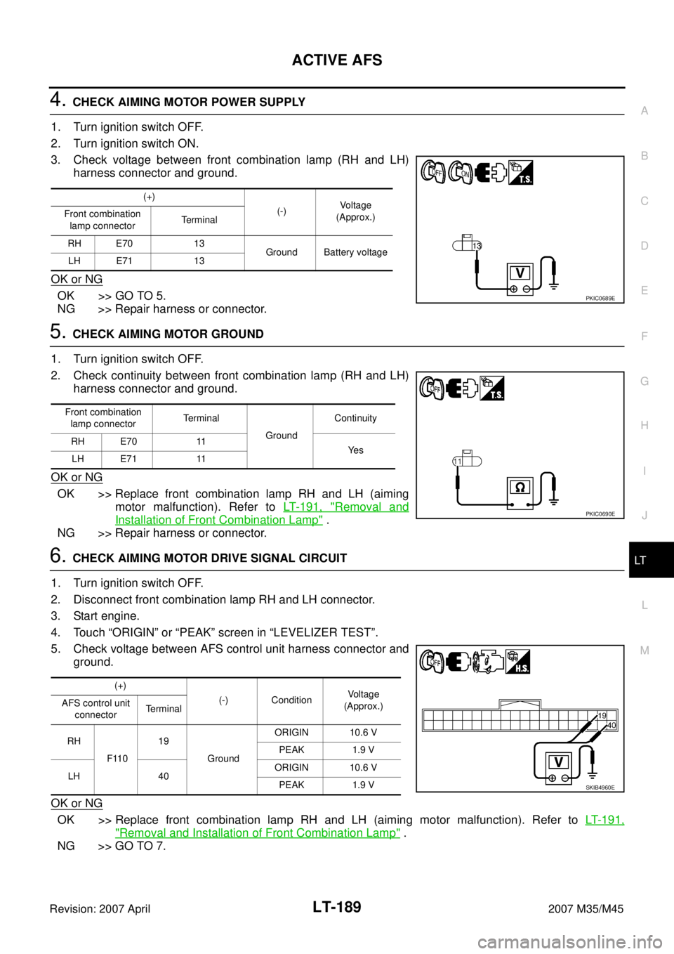
5. Check voltage between AFS control unit harness connector and
ground.
OK or NG
OK >> Replace front combination lamp RH and LH (aiming motor malfunction). Refer to LT- 1 9 1 ,
"Removal and Installation of Front Combination Lamp" .
NG >> GO TO 7.
(+)
(-)Voltage
(Approx.) Front combination
lamp connectorTerminal
RH E70 13
Ground Battery voltage
LH E71 13
PKIC0689E
Front combination
lamp connectorTerminal
GroundContinuity
RH E70 11
Ye s
LH E71 11
PKIC0690E
(+)
(-) ConditionVoltage
(Approx.) AFS control unit
connectorTerminal
RH
F11019
GroundORIGIN 10.6 V
PEAK 1.9 V
LH 40ORIGIN 10.6 V
PEAK 1.9 V
SKIB4960E
Page 3654 of 4647
FRONT FOG LAMP
LT-203
C
D
E
F
G
H
I
J
L
MA
B
LT
Revision: 2007 April2007 M35/M45
Terminals and Reference Values for IPDM E/RNKS003R9
How to Perform Trouble DiagnosesNKS003RA
1. Confirm the symptom or customer complaint.
2. Understand operation description and function description. Refer to LT- 1 9 4 , "
System Description" .
3. Perform the Preliminary Check. Refer to LT- 2 0 3 , "
Preliminary Check" .
4. Check symptom and repair or replace the cause of malfunction.
5. Does the front fog lamp operate normally? If YES, GO TO 6. If NO, GO TO 4.
6. INSPECTION END
Preliminary CheckNKS003RB
CHECK POWER SUPPLY AND GROUND CIRCUIT
1. CHECK FUSES AND FUSIBLE LINK
Check for blown fuses and fusible link.
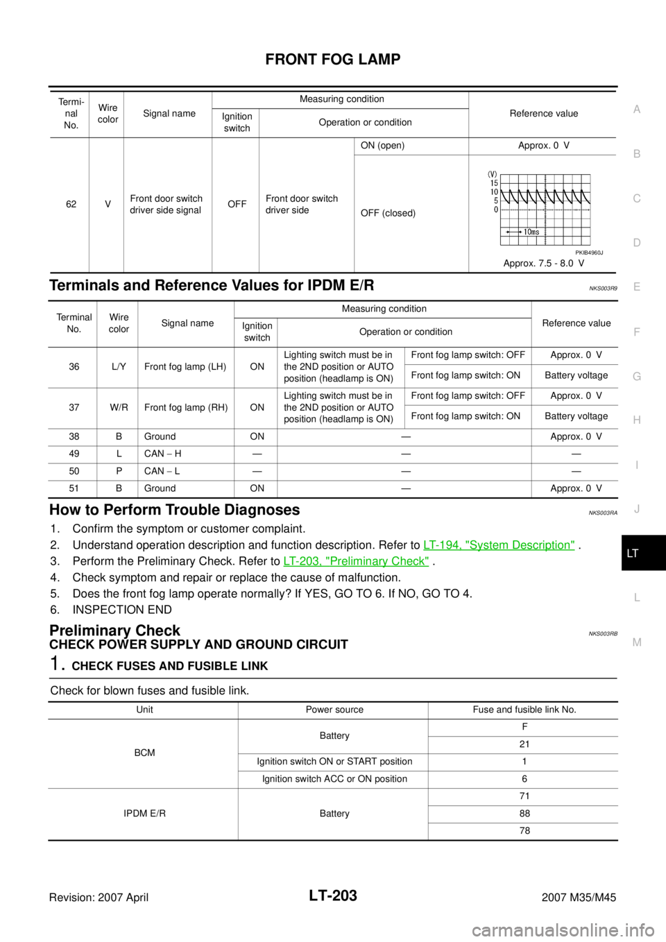
62 VFront door switch
driver side signalOFFFront door switch
driver sideON (open) Approx. 0 V
OFF (closed)
Approx. 7.5 - 8.0 V Te r m i -
nal
No.Wire
colorSignal nameMeasuring condition
Reference value
Ignition
switchOperation or condition
PKIB4960J
Te r m i n a l
No.Wire
colorSignal nameMeasuring condition
Reference value
Ignition
switchOperation or condition
36 L/Y Front fog lamp (LH) ONLighting switch must be in
the 2ND position or AUTO
position (headlamp is ON)Front fog lamp switch: OFF Approx. 0 V
Front fog lamp switch: ON Battery voltage
37 W/R Front fog lamp (RH) ONLighting switch must be in
the 2ND position or AUTO
position (headlamp is ON)Front fog lamp switch: OFF Approx. 0 V
Front fog lamp switch: ON Battery voltage
38 B Ground ON — Approx. 0 V
49 L CAN − H— — —
50 P CAN − L— — —
51 B Ground ON — Approx. 0 V
Unit Power source Fuse and fusible link No.
BCMBatteryF
21
Ignition switch ON or START position 1
Ignition switch ACC or ON position 6
IPDM E/R Battery71
88
78
Page 3659 of 4647
LT-208
FRONT FOG LAMP
Revision: 2007 April2007 M35/M45
Front Fog Lamp Does Not Illuminate (One Side)NKS003RF
1. CHECK BULB
Check bulb of fog lamp which does not illuminate.
OK or NG
OK >> GO TO 2.
NG >> Replace front fog lamp bulb.
2. CHECK FOG LAMP INPUT SIGNAL
1. Turn ignition switch OFF.
2. Disconnect front fog lamp RH or LH connector.
3. Turn ignition switch ON.
4. Lighting switch is turned 2ND position and fog lamp ON position.
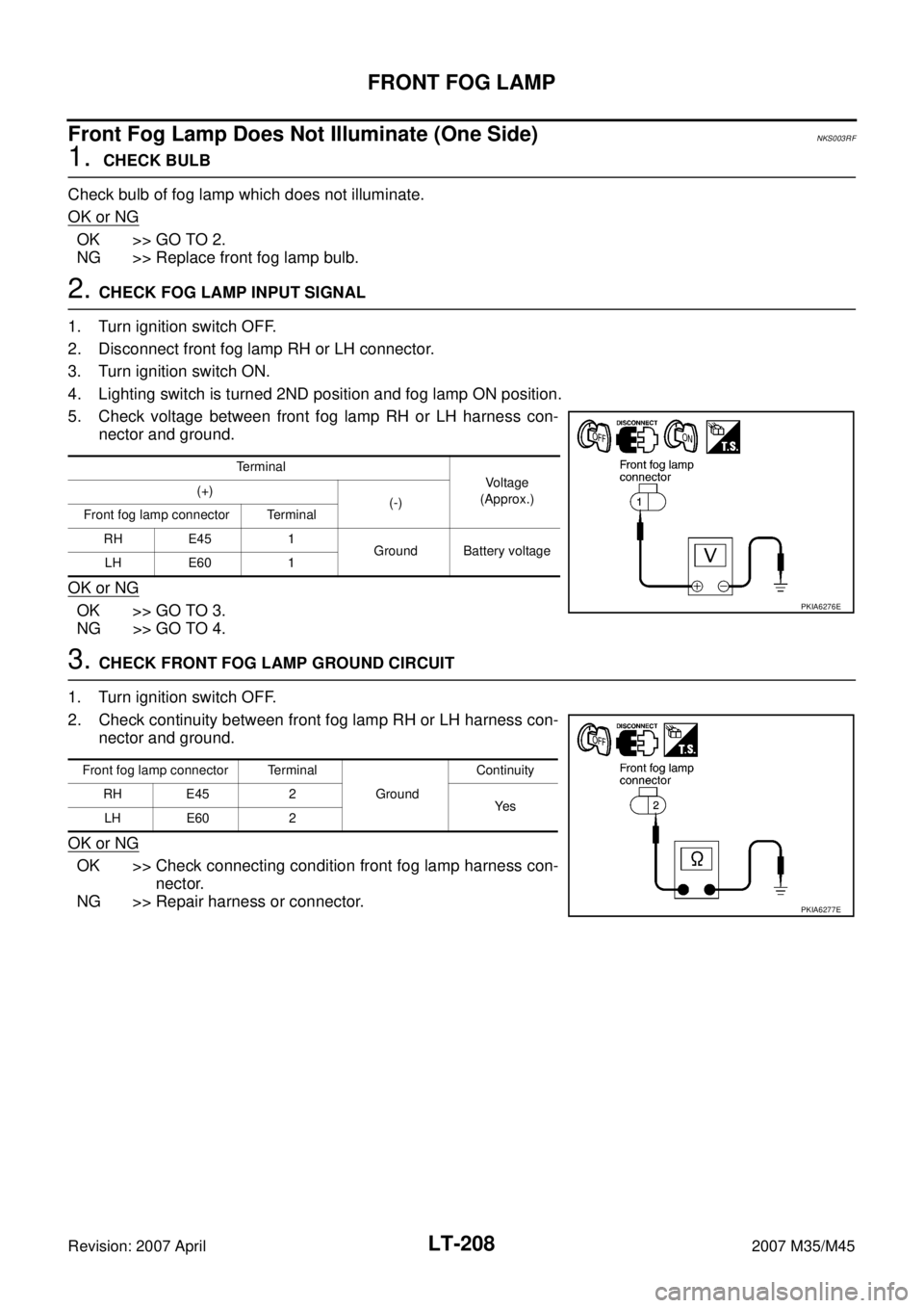
5. Check voltage between front fog lamp RH or LH harness con-
nector and ground.
OK or NG
OK >> GO TO 3.
NG >> GO TO 4.
3. CHECK FRONT FOG LAMP GROUND CIRCUIT
1. Turn ignition switch OFF.
2. Check continuity between front fog lamp RH or LH harness con-
nector and ground.
OK or NG
OK >> Check connecting condition front fog lamp harness con-
nector.
NG >> Repair harness or connector.
Terminal
Voltage
(Approx.) (+)
(-)
Front fog lamp connector Terminal
RH E45 1
Ground Battery voltage
LH E60 1
PKIA6276E
Front fog lamp connector Terminal
Ground Continuity
RH E45 2
Ye s
LH E60 2
PKIA6277E
Page 3672 of 4647
TURN SIGNAL AND HAZARD WARNING LAMPS
LT-221
C
D
E
F
G
H
I
J
L
MA
B
LT
Revision: 2007 April2007 M35/M45
How to Perform Trouble DiagnosesNKS003RR
1. Confirm the symptom or customer complaint.
2. Understand operation description and function description. Refer to LT- 2 1 2 , "
System Description" .
3. Perform the Preliminary Check. Refer to LT- 2 2 2 , "
Preliminary Check" .
4. Check symptom and repair or replace the cause of malfunction.
5. Do turn signal and hazard warning lamps operate normally? If YES, GO TO 6. If NO, GO TO 4.
6. INSPECTION END
45 GFlasher output
(Left)ON Turn signal switchTo l e f t
OFF Approx. 0 V
46 LFlasher output
(Right)ON Turn signal switchTo right
OFF Approx. 0 V
52 B Ground ON — Approx. 0 V
55 WBattery power
supplyOFF — Battery voltage Terminal
No.Wire
colorSignal nameMeasuring condition
Reference value
Ignition
switchOperation or condition
SKIA3009J
SKIA3009J
Page 3677 of 4647
LT-226
TURN SIGNAL AND HAZARD WARNING LAMPS
Revision: 2007 April2007 M35/M45
Hazard Warning Lamp Does Not Operate But Turn Signal Lamp OperateNKS003RV
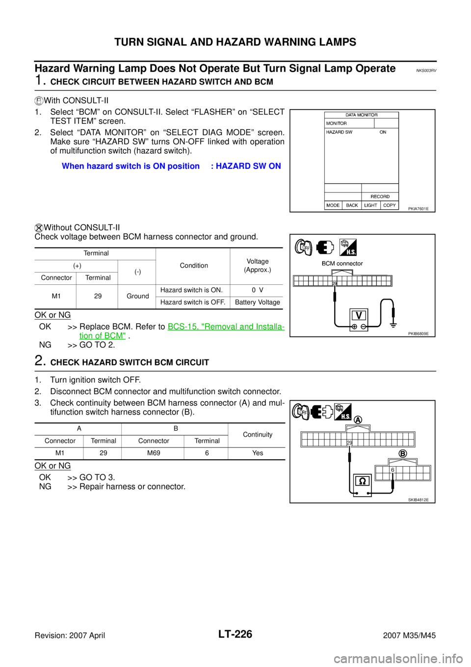
1. CHECK CIRCUIT BETWEEN HAZARD SWITCH AND BCM
With CONSULT-II
1. Select “BCM” on CONSULT-II. Select “FLASHER” on “SELECT
TEST ITEM” screen.
2. Select “DATA MONITOR” on “SELECT DIAG MODE” screen.
Make sure “HAZARD SW” turns ON-OFF linked with operation
of multifunction switch (hazard switch).
Without CONSULT-II
Check voltage between BCM harness connector and ground.
OK or NG
OK >> Replace BCM. Refer to BCS-15, "Removal and Installa-
tion of BCM" .
NG >> GO TO 2.
2. CHECK HAZARD SWITCH BCM CIRCUIT
1. Turn ignition switch OFF.
2. Disconnect BCM connector and multifunction switch connector.
3. Check continuity between BCM harness connector (A) and mul-
tifunction switch harness connector (B).
OK or NG
OK >> GO TO 3.
NG >> Repair harness or connector.When hazard switch is ON position : HAZARD SW ON
PKIA7601E
Terminal
ConditionVoltage
(Approx.) (+)
(-)
Connector Terminal
M1 29 GroundHazard switch is ON. 0 V
Hazard switch is OFF. Battery Voltage
PKIB6809E
AB
Continuity
Connector Terminal Connector Terminal
M1 29 M69 6 Yes
SKIB4812E
Page 3678 of 4647
TURN SIGNAL AND HAZARD WARNING LAMPS
LT-227
C
D
E
F
G
H
I
J
L
MA
B
LT
Revision: 2007 April2007 M35/M45
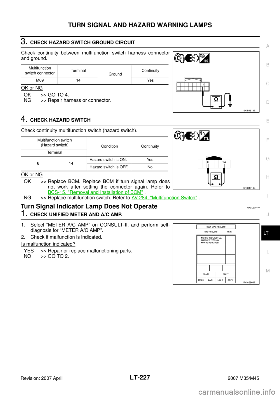
3. CHECK HAZARD SWITCH GROUND CIRCUIT
Check continuity between multifunction switch harness connector
and ground.
OK or NG
OK >> GO TO 4.
NG >> Repair harness or connector.
4. CHECK HAZARD SWITCH
Check continuity multifunction switch (hazard switch).
OK or NG
OK >> Replace BCM. Replace BCM if turn signal lamp does
not work after setting the connector again. Refer to
BCS-15, "
Removal and Installation of BCM" .
NG >> Replace multifunction switch. Refer to AV- 2 8 4 , "
Multifunction Switch" .
Turn Signal Indicator Lamp Does Not OperateNKS003RW
1. CHECK UNIFIED METER AND A/C AMP.
1. Select “METER A/C AMP” on CONSULT-II, and perform self-
diagnosis for “METER A/C AMP”.
2. Check if malfunction is indicated.
Is malfunction indicated?
YES >> Repair or replace malfunctioning parts.
NO >> GO TO 2.
Multifunction
switch connectorTerminal
GroundContinuity
M69 14 Yes
SKIB4813E
Multifunction switch
(Hazard switch)
Condition Continuity
Te r m i n a l
614Hazard switch is ON. Yes
Hazard switch is OFF. No
SKIB4814E
PKIA6866E