Page 4533 of 4647

TF-44
TRANSFER ASSEMBLY
Revision: 2007 April2007 M35/M45
TRANSFER ASSEMBLYPFP:33100
Removal and InstallationNDS000E4
REMOVAL
1. Remove exhaust front tube with power tool. Refer to EX-3, "EXHAUST SYSTEM" .
2. Remove front and rear propeller shaft. Refer to PR-4, "
FRONT PROPELLER SHAFT" and PR-6, "REAR
PROPELLER SHAFT" .
3. Disconnect transfer assembly harness connector and separate harness from transfer assembly.
4. Remove air breather hose. Refer to TF-43, "
AIR BREATHER HOSE" .
5. Remove control rod. Refer to AT- 2 2 6 , "
Control Rod Removal and Installation" .
6. Support transfer assembly and transmission assembly with a jack.
7. Remove rear engine mounting member and engine mounting insulator with power tool. Refer to EM-114,
"ENGINE ASSEMBLY" .
8. Lower jack to the position where the top transfer mounting bolts
can be removed.
9. Remove transfer mounting bolts with power tool and separate
transfer from transmission.
CAUTION:
Secure transfer assembly and transmission assembly to a
jack.
INSTALLATION
Note the following, and install in the reverse order of removal.
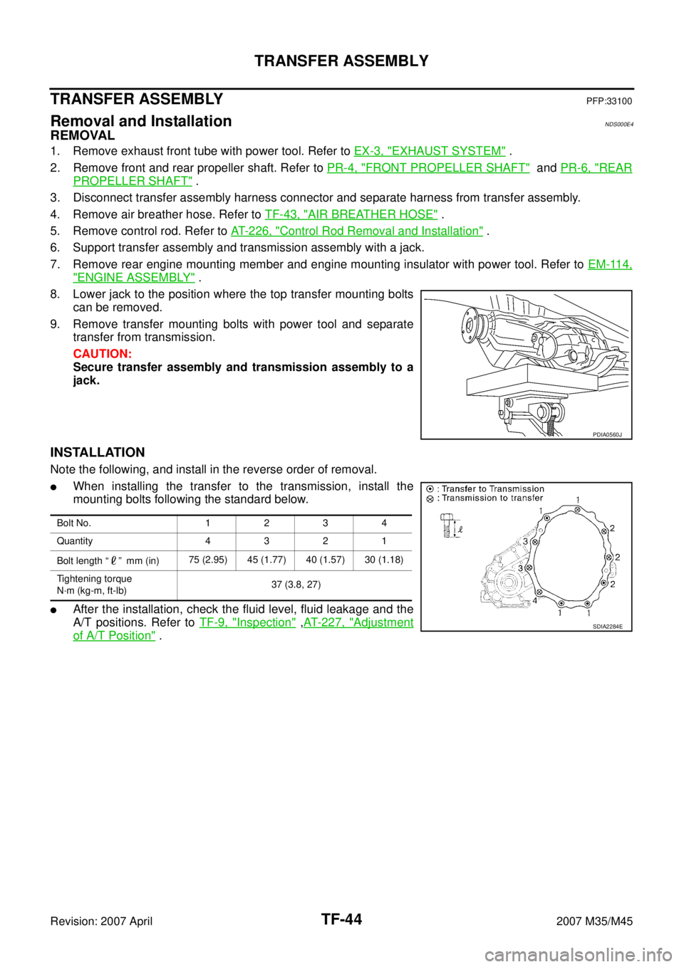
�When installing the transfer to the transmission, install the
mounting bolts following the standard below.
�After the installation, check the fluid level, fluid leakage and the
A/T positions. Refer to TF-9, "
Inspection" ,AT- 2 2 7 , "Adjustment
of A/T Position" .
PDIA0560J
Bolt No. 1 2 3 4
Quantity 4 3 2 1
Bolt length “ ” mm (in)75 (2.95) 45 (1.77) 40 (1.57) 30 (1.18)
Tightening torque
N·m (kg-m, ft-lb)37 (3.8, 27)
SDIA2284E
Page 4548 of 4647
SERVICE DATA AND SPECIFICATIONS (SDS)
TF-59
C
E
F
G
H
I
J
K
L
MA
B
TF
Revision: 2007 April2007 M35/M45
SERVICE DATA AND SPECIFICATIONS (SDS)PFP:00030
General SpecificationsNDS000E6
Applied model VQ35DE
Transfer model ETX13B
Fluid capacity (Approx.)
1.25 (2-5/8 US pt, 2-1/4 lmp pt)
Page 4634 of 4647

FRONT WIPER AND WASHER SYSTEM
WW-43
C
D
E
F
G
H
I
J
L
MA
B
WW
Revision: 2007 April2007 M35/M45
Removal and Installation of Front Wiper Arms, Adjustment of Wiper Arms Stop
Location
NKS003WY
REMOVAL
1. Turn wiper switch ON to operate wiper motor, and then turn wiper switch OFF (auto stop).
2. Open hood, remove arm caps, and remove wiper arm nuts.
3. Raise wiper arms, and remove wiper arms from the vehicle.
INSTALLATION
1. Clean up the pivot area as shown in the figure. This will reduce
possibility of wiper arm looseness.
2. Prior to wiper arm installation, turn on wiper switch to operate
wiper motor and then turn it “OFF” (auto stop).
3. Push wiper arm onto pivot shaft, paying attention to blind spline.
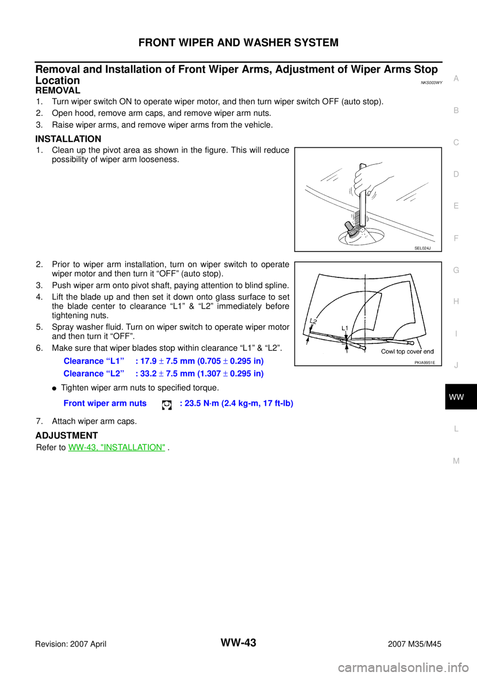
4. Lift the blade up and then set it down onto glass surface to set
the blade center to clearance “L1” & “L2” immediately before
tightening nuts.
5. Spray washer fluid. Turn on wiper switch to operate wiper motor
and then turn it “OFF”.
6. Make sure that wiper blades stop within clearance “L1” & “L2”.
�Tighten wiper arm nuts to specified torque.
7. Attach wiper arm caps.
ADJUSTMENT
Refer to WW-43, "INSTALLATION" .
SEL024J
Clearance “L1” : 17.9 ± 7.5 mm (0.705 ± 0.295 in)
Clearance “L2” : 33.2 ± 7.5 mm (1.307 ± 0.295 in)
Front wiper arm nuts : 23.5 N·m (2.4 kg-m, 17 ft-lb)PKIA9951E
Page 4639 of 4647
WW-48
FRONT WIPER AND WASHER SYSTEM
Revision: 2007 April2007 M35/M45
Removal and Installation of Washer TankNKS003X7
: Vehicle front
REMOVAL
1. Remove engine room cover (RH). Refer to EM-15, "Removal and Installation" .
2. Remove clip (A) and pull washer tank inlet (1) out of washer
tank.
3. Remove front bumper. Refer to EI-11, "
Removal and Installation" .
4. Disconnect washer pump connector and wash fluid level sensor connector.
5. Remove washer tank mounting nuts (A) and remove bolt (B).
6. Remove washer tube, and remove washer tank (1) from vehicle.
INSTALLATION
Note the following, and installation is the reverse order of removal.
CAUTION:
After installation, add water up to the upper level of washer tank inlet, and check for water leaks.
SKIB4258E
SKIB4259E
Washer tank mounting nuts : 4.5 N·m (0.46 kg-m, 40 in-lb)
Washer tank mounting bolt : 4.5 N·m (0.46 kg-m, 40 in-lb)