Page 4021 of 4647
PS-40
HYDRAULIC LINE
Revision: 2007 April2007 M35/M45
10. Eye-bolt 11. Copper washer 12. Eye-joint (assembled to high-pres-
sure side hose)
13. Pressure sensor 14. Oil pump bracket
Refer to GI-11, "
Components" , and the followings for the symbols in the figure.
: Apply power steering fluid.
Page 4023 of 4647
PS-42
HYDRAULIC LINE
Revision: 2007 April2007 M35/M45
Refer to GI-11, "Components" , and the followings for the symbols in the figure.
: Apply power steering fluid.
Page 4025 of 4647
PS-44
HYDRAULIC LINE
Revision: 2007 April2007 M35/M45
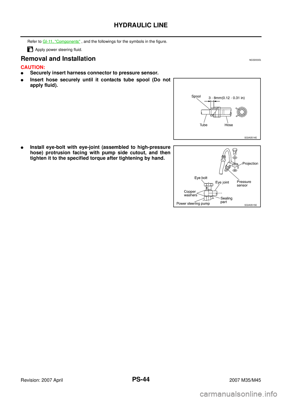
Removal and InstallationNGS000DL
CAUTION:
�Securely insert harness connector to pressure sensor.
�Insert hose securely until it contacts tube spool (Do not
apply fluid).
�Install eye-bolt with eye-joint (assembled to high-pressure
hose) protrusion facing with pump side cutout, and then
tighten it to the specified torque after tightening by hand.
Refer to GI-11, "Components" , and the followings for the symbols in the figure.
: Apply power steering fluid.
SGIA0514E
SGIA0515E
Page 4027 of 4647

Revision: 2007 April2007 M35/M45
Steering GearNGS000DP
STEERING OUTER SOCKET AND INNER SOCKET
RACK STROKE
RACK SLIDING FORCE
Oil PumpNGS000DR
Steering Fluid")
PS-46
SERVICE DATA AND SPECIFICATIONS (SDS)
Revision: 2007 April2007 M35/M45
Steering GearNGS000DP
STEERING OUTER SOCKET AND INNER SOCKET
RACK STROKE
RACK SLIDING FORCE
Oil PumpNGS000DR
Steering FluidNGS000DS
Steering gear typePR26AF
Outer socketSwinging torque 0.3 – 2.9 N·m (0.03 – 0.29 kg-m, 3 – 25 in-lb)
Measurement on spring balance
�Measuring point at cotter pin hole of stud4.81 – 45.7 N (0.5 – 4.7 kg, 1.1 – 10.4 lb)
Rotating torque 0.3 – 2.9 N·m (0.03 – 0.29 kg-m, 3 – 25 in-lb)
Axial end play 0.5 mm (0.020 in) or less
Inner socketSwinging torque 1.0 – 7.8 N·m (0.11 – 0.79 kg-m, 9.0 – 69 in-lb)
Measurement on spring balance
�Measuring point at *mark shown in the
figure8.9 – 64 N (0.9 – 6.5 kg, 2.0 – 14.3 lb)
Axial end play 0.2 mm (0.008 in) or less
Inner socket length L63.9 mm (2.516 in) (2WD)
55.2 mm (2.173 in) (AWD)
SGIA0950E
Steering gear modelPR26AF
Drive type 2WD AWD
Rack neutral position, dimension L (rack stroke) 68.5 mm (2.697 in) 67.0 mm (2.638 in)
SGIA0877E
Rack sliding force2WD 195 – 258 N (19.9 – 26.3 kg, 44 – 58 lb)
AWD 227 – 305 N (23.2 – 31.1 kg, 51 – 69 lb)
Oil pump relief hydraulic pressure
8,520 – 9,320 kPa (86.9 – 95.1 kg/cm2 , 1,235 – 1,351 psi)
Fluid capacity
Approx. 1.0 (1-1/8 US qt, 7/8 Imp qt)
Page 4078 of 4647

DIFFERENTIAL GEAR OIL
RFD-9
C
E
F
G
H
I
J
K
L
MA
B
RFD
Revision: 2007 April2007 M35/M45
DIFFERENTIAL GEAR OILPFP:KLD30
Changing Differential Gear OilNDS000F3
DRAINING
1. Stop engine.
2. Remove drain plug (1) and drain gear oil.
3. Set a gasket on drain plug (1) and install it to final drive assem-
bly and tighten to the specified torque. Refer to RFD-18, "
COM-
PONENTS" .
CAUTION:
Do not reuse gasket.
FILLING
1. Remove filler plug (1). Fill with new gear oil until oil level reaches
the specified level near filler plug mounting hole.
2. After refilling oil, check oil level. Set a gasket to filler plug (1),
then install it to final drive assembly. Refer to RFD-18, "
COMPO-
NENTS" .
CAUTION:
Do not reuse gasket.
Checking Differential Gear OilNDS000F4
OIL LEAKAGE AND OIL LEVEL
�Make sure that oil is not leaking from final drive assembly or around it.
�Remove filler plug (1) and check oil level from filler plug mount-
ing hole as shown in the figure.
CAUTION:
Do not start engine while checking oil level.
�Set a gasket on filler plug (1) and install it on final drive assem-
bly. Refer to RFD-18, "
COMPONENTS" .
CAUTION:
Do not reuse gasket.
PDIA0748J
Oil grade and Viscosity:
Refer to MA-12, "
Fluids and Lubricants" .
Oil capacity:
Approx. 1.4 (3 US pt, 2-1/2 Imp pt)
PDIA0749J
PDIA0749J
Page 4166 of 4647

BATTERY
SC-5
C
D
E
F
G
H
I
J
L
MA
B
SC
Revision: 2007 April2007 M35/M45
CHECKING ELECTROLYTE LEVEL
WARNING:
Never allow battery fluid to come in contact with skin, eyes, fabrics, or painted surfaces. After touch-
ing a battery, never touch or rub your eyes until you have thoroughly washed your hands. If acid con-
tacts eyes, skin or clothing, immediately flush with water for 15 minutes and seek medical attention.
�Remove the cell plug using a suitable tool.
�Add distilled water up to the MAX level.
Sulphation
A battery will be completely discharged if it is left unattended
for a long time and the specific gravity will become less than
1.100. This may result in sulphation on the cell plates.
To determine if a battery has been “sulphated”, note its voltage
and current when charging it. As shown in the figure, less cur-
rent and higher voltage are observed in the initial stage of
charging sulphated batteries.
A sulphated battery may sometimes be brought back into ser-
vice by means of a long, slow charge, 12 hours or more, fol-
lowed by a battery capacity test.
SPECIFIC GRAVITY CHECK
1. Read hydrometer and thermometer indications at eye level.
2. Use the chart below to correct your hydrometer reading accord-
ing to electrolyte temperature.
Hydrometer Temperature Correction
MEL043F
PKIA2353E
MEL042FA
Battery electrolyte temperature °C (°F) Add to specific gravity reading
71 (160) 0.032
66 (150) 0.028
60 (140) 0.024
54 (130) 0.020
49 (120) 0.016
43 (110) 0.012
38 (100) 0.008
32 (90) 0.004
27 (80) 0
21 (70)−0.004
Page 4448 of 4647
![INFINITI M35 2007 Factory Service Manual TROUBLE DIAGNOSIS
STC-9
[EPS]
C
D
E
F
H
I
J
K
L
MA
B
STC
Revision: 2007 April2007 M35/M45
For Fast and Accurate Trouble DiagnosisNGS000E1
Check the following items with the vehicle stopped
�Is air pre](/manual-img/42/57024/w960_57024-4447.png "INFINITI M35 2007 Factory Service Manual TROUBLE DIAGNOSIS
STC-9
[EPS]
C
D
E
F
H
I
J
K
L
MA
B
STC
Revision: 2007 April2007 M35/M45
For Fast and Accurate Trouble DiagnosisNGS000E1
Check the following items with the vehicle stopped
�Is air pre")
TROUBLE DIAGNOSIS
STC-9
[EPS]
C
D
E
F
H
I
J
K
L
MA
B
STC
Revision: 2007 April2007 M35/M45
For Fast and Accurate Trouble DiagnosisNGS000E1
Check the following items with the vehicle stopped
�Is air pressure and size of tires proper?
�Is the specified part used for the steering wheel?
�Is control unit a genuine part?
�Are there any fluid leakage from steering gear assembly, power steering oil pump, and hydraulic pipes,
etc? Refer to PS-8, "
Checking Fluid Leakage" .
�Is the fluid level proper? Refer to PS-8, "Checking Fluid Level" .
�Is the wheel alignment adjusted properly? Refer to FSU-6, "Wheel Alignment Inspection" (2WD), FSU-24,
"Wheel Alignment Inspection" (AWD).
�Are there any damage or modification to suspension or body resulting in increased weight or altered
ground clearance?
�Check each link installation condition of suspension and axle.
�Check each connector connection condition.
Check the following items while driving the vehicle
�Check conditions when the malfunction occurred (5W 1H).
�Is the engine condition normal?
Basic InspectionNGS000E2
POWER SUPPLY CIRCUIT TERMINAL LOOSENESS AND BATTERY
Check battery terminals for looseness on both positive and negative ones and ground connection. Also make
sure that battery voltage does not drop.
Inspection: Power Steering Control Unit Power Supply Circuit and GroundNGS000E3
1. CHECK POWER STEERING CONTROL UNIT CONNECTOR
Turn ignition switch OFF, disconnect power steering control unit harness connector, and check terminal for
deformation, disconnection, looseness, etc.
OK or NG
OK >> GO TO 2.
NG >> Connector terminal connection is loose, damaged, open, or shorted. Repair or replace the termi-
nal.
2. CHECK POWER STEERING CONTROL UNIT GROUND CIRCUIT
Disconnect power steering control unit harness connector M8, and
then check continuity between power steering control unit harness
connector M8 and ground.
OK or NG
OK >> GO TO 3.
NG >> Ground circuit open or shorted. Repair or replace any
inoperative parts. Terminal 2 – Ground : Continuity exist.
SGIA1231E
Page 4471 of 4647
![INFINITI M35 2007 Factory Service Manual STC-32
[RAS]
TROUBLE DIAGNOSIS
Revision: 2007 April2007 M35/M45
For Fast and Accurate Trouble DiagnosisNGS000EN
Check the following items with the vehicle stopped
�Is air pressure and size of tires pr](/manual-img/42/57024/w960_57024-4470.png "INFINITI M35 2007 Factory Service Manual STC-32
[RAS]
TROUBLE DIAGNOSIS
Revision: 2007 April2007 M35/M45
For Fast and Accurate Trouble DiagnosisNGS000EN
Check the following items with the vehicle stopped
�Is air pressure and size of tires pr")
STC-32
[RAS]
TROUBLE DIAGNOSIS
Revision: 2007 April2007 M35/M45
For Fast and Accurate Trouble DiagnosisNGS000EN
Check the following items with the vehicle stopped
�Is air pressure and size of tires proper?
�Is the specified part used for the steering wheel?
�Is control unit a genuine part?
�Are there any fluid leakage from steering gear assembly, power steering oil pump, and hydraulic pipes,
etc? Refer to PS-8, "
Checking Fluid Leakage" .
�Is the fluid level proper? Refer to PS-8, "Checking Fluid Level" .
�Is the wheel alignment is adjusted properly? Refer to FSU-6, "Wheel Alignment Inspection" (2WD), FSU-
24, "Wheel Alignment Inspection" (AWD).
�Are there any damage or modification to suspension or body resulting in increased weight or altered
ground clearance?
�Check each link installation condition of suspension and axle.
�Is the battery voltage proper?
�Check each connector connection condition.
Check the following items while driving the vehicle
�Conditions when the error occurred (5W 1H).
�Is the engine is normal?
Basic InspectionNGS000EO
BASIC INSPECTION 1: POWER SUPPLY CIRCUIT TERMINAL LOOSENESS AND BATTERY
Check battery terminals for looseness on both positive and negative ones and ground connection. Also make
sure that battery voltage does not drop.
BASIC INSPECTION 2: RAS WARNING LAMP INSPECTION
1. Make sure RAS warning lamp turns on when ignition switch is turned ON.
�If it does not turn on, refer to STC-33, "Trouble Diagnosis Chart" .
2. Make sure that RAS warning lamp turns off when the engine is started after ignition switch is turned ON. If
it does not turn off, perform self-diagnosis. Refer to STC-28, "
SELF-DIAG RESULT MODE" .
3. Always erase DTC memory after completing self-diagnosis. Refer to STC-29, "
How to Erase Self-Diag-
nostic Results" .
BASIC INSPECTION 3: RAS CONTROL UNIT POWER SUPPLY CIRCUIT AND GROUND CIR-
CUIT INSPECTION
1. CHECK RAS CONTROL UNIT CONNECTOR
Turn ignition switch OFF, disconnect RAS control unit harness connector, and check terminal for deformation,
disconnection, looseness, etc.
OK or NG
OK >> GO TO 2.
NG >> Poor connection of connector terminal. Repair or replace the terminal.
2. CHECK RAS CONTROL UNIT GROUND CIRCUIT
1. Disconnect RAS control unit harness connector B476, and then
check continuity between RAS control unit harness connector
B476 and ground.
OK or NG
OK >> GO TO 3.
NG >> Ground circuit open or shorted. Repair or replace any
inoperative parts. Terminal 34 – Ground : Continuity should exit.
SGIA1244E

13. Pressure sensor 14. Oil pump bracket
Refer to GI-11, \"")