Page 4007 of 4647
 into rack assembly piston (rack Teflon
ring).
c. Push retainer to adjusting screw side by hand, a")
PS-26
POWER STEERING GEAR AND LINKAGE
Revision: 2007 April2007 M35/M45
b. Insert rack oil seal (inner) into rack assembly piston (rack Teflon
ring).
c. Push retainer to adjusting screw side by hand, and move the
rack assembly inside the gear housing assembly so that the
rack oil seal (inner) can be pressed against the gear housing
assembly.
d. Wrap an OHP sheet [approximately 70 mm (2.76 in) × 100 mm
(3.94 in)]. Around the edge to avoid damaging rack oil seal
(outer). Install rack oil seal over sheet. Then, pull oil seal along
with OHP sheet until they pass rack edge, and remove OHP
sheet.
e. Install end cover assembly to rack edge, and move rack oil seal
(outer) until it contacts with gear housing assembly.
5. Tighten end cover assembly to specified torque using a 36 mm
(1.42 in) open head (suitable tool).
CAUTION:
Do not damage rack assembly. Replace it if damaged
because it may cause fluid leakage.
6. Crimp gear housing assembly at one point using a punch as
shown in the figure so as to prevent end cover assembly from
getting loose after tightening end cover assembly.
7. Apply recommended fluid to O-ring, and then install O-ring to
gear housing assembly.
8. Install gear-sub assembly to gear housing assembly.
9. Install power steering solenoid valve to gear-sub assembly.
10. Decide on the neutral position for the rack.
11. Install rear cover cap to gear sub-assembly.
CAUTION:
Make sure that the projection of rear cover cap is aligned
with the marking position of gear housing assembly.
SGIA0671E
SGIA0157E
SST081B
SGIA0871E
Drive type 2WD AWD
Rack stroke L 68.5 mm (2.697 in) 67.0 mm (2.638 in)
SGIA0877E
Page 4011 of 4647

PS-30
POWER STEERING OIL PUMP
Revision: 2007 April2007 M35/M45
POWER STEERING OIL PUMPPFP:49110
On-Vehicle Inspection and ServiceNGS000DE
CHECKING RELIEF OIL PRESSURE
CAUTION:
Make sure that belt tension is normal before starting the following procedure.
1. Connect the hydraulic pressure gauge [SST] between oil pump
discharge connector and high-pressure hose. Bleed air from the
hydraulic circuit while opening valve fully. Refer to PS-8, "
Air
Bleeding Hydraulic System" .
2. Start engine. Run engine until oil temperature reaches 50 to
80°C (122 to 176°F).
CAUTION:
�Leave the valve of the hydraulic pressure gauge [SST]
fully open while starting and running engine. If engine is
started with the valve closed, the hydraulic pressure in
oil pump goes up to the relief pressure along with
unusual increase of oil temperature.
�Be sure to keep hose clear of belts and other parts when
engine is started.
3. Fully close the hydraulic pressure gauge [SST] valve with
engine at idle and measure the relief oil pressure.
CAUTION:
Never keep valve closed for 10 seconds or longer.
4. Open the valve slowly after measuring. Repair oil pump if the
relief oil pressure is outside the standard. Refer to PS-31, "
Dis-
assembly and Assembly (Models with VK45DE)" , PS-35, "Disassembly and Assembly (Models with
VQ35DE)" .
5. After inspection, disconnect the hydraulic pressure gauge [SST] from hydraulic circuit, then add fluid and
bleed air. Refer to PS-8, "
Air Bleeding Hydraulic System" .
Removal and InstallationNGS000DF
REMOVAL
1. Drain power steering fluid from reservoir tank.
2. Remove undercover from vehicle with a power tool.
3. Loosen drive belt. Refer to EM-16, "
DRIVE BELTS" (VQ35DE), EM-174, "DRIVE BELTS" (VK45DE).
4. Remove drive belt from oil pump pulley.
5. Remove piping of high pressure and low pressure (drain fluid from their pipings). Refer to PS-39,
"HYDRAULIC LINE" .
6. Remove power steering oil pump mounting bolts, and then remove power steering oil pump. Refer to PS-
39, "Removal and Installation" .
INSTALLATION
Installation is the reverse order of removal. For tightening torque, refer to PS-39, "HYDRAULIC LINE" .
�Perform the following procedure after installing.
–Adjust belt tension (VQ35DE). Refer to EM-16, "Tension Adjustment" .
–About the installation of VK45DE drive belt, refer to EM-174, "Tension Adjustment" .
–Bleed air. Refer to PS-8, "Air Bleeding Hydraulic System" . Relief oil pressure:
8,520 - 9,320 kpa (86.9 - 95.1 kg/cm
2 , 1,235 - 1,351 psi)
SGIA0915E
Page 4012 of 4647
POWER STEERING OIL PUMP
PS-31
C
D
E
F
H
I
J
K
L
MA
B
PS
Revision: 2007 April2007 M35/M45
Disassembly and Assembly (Models with VK45DE)NGS000DG
COMPONENTS
INSPECTION BEFORE DISASSEMBLY
Disassemble oil pump only when the following malfunctions occur.
�If oil leakage is found on oil pump.
�Oil pump pulley is damaged or deformed.
�Performance of oil pump is low.
1. Pulley 2. Snap ring 3. Drive shaft
4. Joint 5. O-ring 6. Connector bolt
7. Flow control valve 8. Spring 9. Oil seal
10. Suction pipe 11. O-ring 12. Body assembly
13. O-ring 14. Side plate 15. Vane
16. Rotor 17. Cam ring 18. Cartridge
19. Dowel pin 20. Gasket 21. Rear cover
22. Copper washer
Refer to GI-11, "
Components" , and the followings for the symbols in the figure.
: Apply power steering fluid.
: Apply multi-purpose grease.
SGIA1187E
Page 4014 of 4647

POWER STEERING OIL PUMP
PS-33
C
D
E
F
H
I
J
K
L
MA
B
PS
Revision: 2007 April2007 M35/M45
ASSEMBLY
NOTE:
Secure oil pump in a vise if necessary.
CAUTION:
Use copper plates when securing in a vise.
1. Apply recommended grease to oil seal lips (1). Apply recom-
mended fluid to around oil seal, and then install oil seal to body
assembly.
2. Apply recommended fluid to drive shaft, and press drive shaft
into body assembly, then install snap ring.
3. Apply recommended fluid to O-ring, and then install O-ring into
body assembly.
4. Install side plate to body assembly.
5. Install dowel pin (3) into dowel pin hole (A), and then install cam
ring (2) pointing it's D
1 side toward the body assembly (1) side
as shown in the figure.
�When installing cam ring, turn carved face with a letter E (B)
of it to rear cover.
CAUTION:
Do not confuse the assembling direction of cam ring. If
cam ring is installed facing the incorrect direction, it may
cause oil pump operation malfunction.
6. Install rotor to body assembly.
SGIA1150E
SGIA0422E
SGIA1166E
Page 4015 of 4647
PS-34
POWER STEERING OIL PUMP
Revision: 2007 April2007 M35/M45
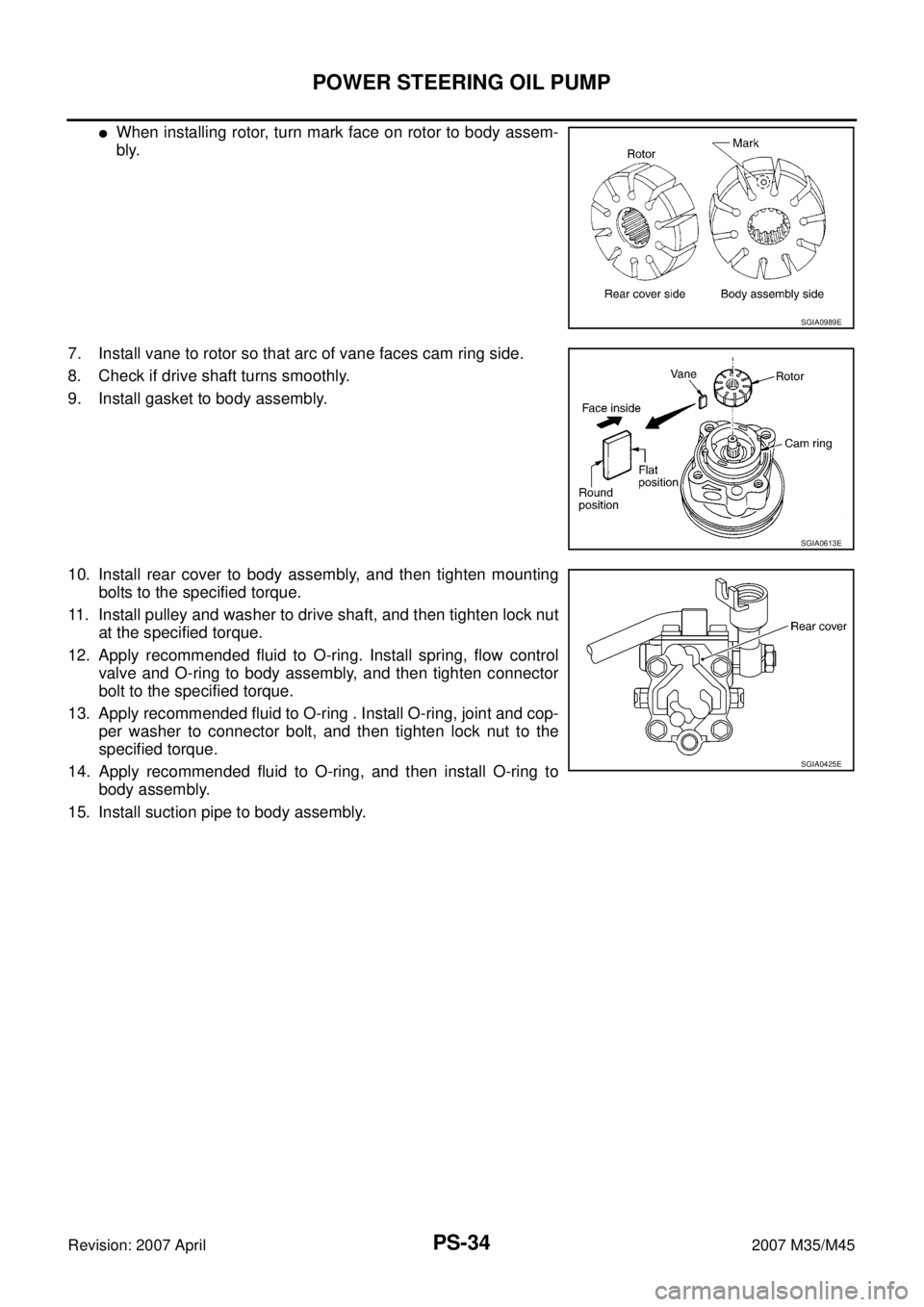
�When installing rotor, turn mark face on rotor to body assem-
bly.
7. Install vane to rotor so that arc of vane faces cam ring side.
8. Check if drive shaft turns smoothly.
9. Install gasket to body assembly.
10. Install rear cover to body assembly, and then tighten mounting
bolts to the specified torque.
11. Install pulley and washer to drive shaft, and then tighten lock nut
at the specified torque.
12. Apply recommended fluid to O-ring. Install spring, flow control
valve and O-ring to body assembly, and then tighten connector
bolt to the specified torque.
13. Apply recommended fluid to O-ring . Install O-ring, joint and cop-
per washer to connector bolt, and then tighten lock nut to the
specified torque.
14. Apply recommended fluid to O-ring, and then install O-ring to
body assembly.
15. Install suction pipe to body assembly.
SGIA0989E
SGIA0613E
SGIA0425E
Page 4016 of 4647
POWER STEERING OIL PUMP
PS-35
C
D
E
F
H
I
J
K
L
MA
B
PS
Revision: 2007 April2007 M35/M45
Disassembly and Assembly (Models with VQ35DE)NGS000DH
COMPONENTS
INSPECTION BEFORE DISASSEMBLY
Disassemble oil pump only when the following malfunctions occur.
�If oil leakage is found on oil pump.
�Oil pump pulley is damaged or deformed.
�Performance of oil pump is low.
1. Pulley 2. Oil seal 3. Bracket
4. Body assembly 5. Suction pipe 6. O-ring
7. Flow control valve B assembly 8. Flow control valve spring 9. Flow control valve A
10. Dowel pin 11. Front side plate 12. Vane
13. Rotor 14. Rotor snap ring 15. Cam ring
16. Rear side plate 17. O-ring 18. Teflon ring
19. O-ring 20. Rear cover 21. Cartridge
Refer to GI-11, "
Components" , and the followings for the symbols in the figure.
: Apply power steering fluid.
: Apply multi-purpose grease.
SGIA1188E
Page 4018 of 4647

POWER STEERING OIL PUMP
PS-37
C
D
E
F
H
I
J
K
L
MA
B
PS
Revision: 2007 April2007 M35/M45
ASSEMBLY
NOTE:
Secure oil pump in a vise if necessary.
CAUTION:
Use copper plates when securing in a vise.
1. Apply recommended grease to oil seal lips. Apply recommended
fluid to around oil seal, and then install oil seal to body assembly
using the drift [SST].
2. Install bracket to body assembly, and then tighten mounting
bolts to the specified torque.
3. If dowel pin has been removed, insert it into body assembly by
hand. If cannot be inserted by hand, lightly tap with a hammer.
4. Install flow control valve A, flow control valve spring and flow
control valve B assembly as shown in the figure.
5. Install front side plate (3) with dowel pin (2) on flow control valve
A (1) side as shown in the figure aligning with front side plate
cutout (A) to body assembly (4).
6. Install cam ring as shown in the figure.
7. Install pulley to body assembly.
CAUTION:
Do not damage oil seal when installing pulley.
SGIA0527E
SGIA0526E
SGIA1189E
SGIA0612E
Page 4019 of 4647

PS-38
POWER STEERING OIL PUMP
Revision: 2007 April2007 M35/M45
8. Install rotor so that mark faces body assembly, and then install it
to pulley shaft.
9. Install vane to rotor so that arc of vane faces cam ring side.
10. Install rotor snap ring to slit of pulley shaft using a hammer and a
10 mm (0.39 in) socket.
CAUTION:
�Do not damage rotor and pulley shaft.
�Power steering oil pump assembly must be replaced if
rotor is damaged.
11. Install rear side plate with dowel pin A on flow control valve A
side as shown in the figure aligning with rear side plate cutout B
to cartridge.
12. Apply recommended fluid to O-ring, and then install O-ring to
body assembly.
13. Apply recommended fluid to O-ring, and then install O-ring to
rear side plate.
14. Apply recommended fluid to Teflon ring, and then install Teflon
ring to rear side plate.
15. Install rear cover to body assembly, and then tighten mounting
bolts to the specified torque.
16. Apply recommended fluid to O-ring, and then install O-ring to body assembly.
17. Install suction pipe to body assembly.
SGIA0989E
SGIA0613E
SGIA0063E
SGIA0530E
NGS000DG
COMPONENTS
INSPECTION BEFORE DISASSEMBLY
Disassemble oil")
NGS000DH
COMPONENTS
INSPECTION BEFORE DISASSEMBLY
Disassemble oil")