Page 4194 of 4647

CHARGING SYSTEM
SC-33
C
D
E
F
G
H
I
J
L
MA
B
SC
Revision: 2007 April2007 M35/M45
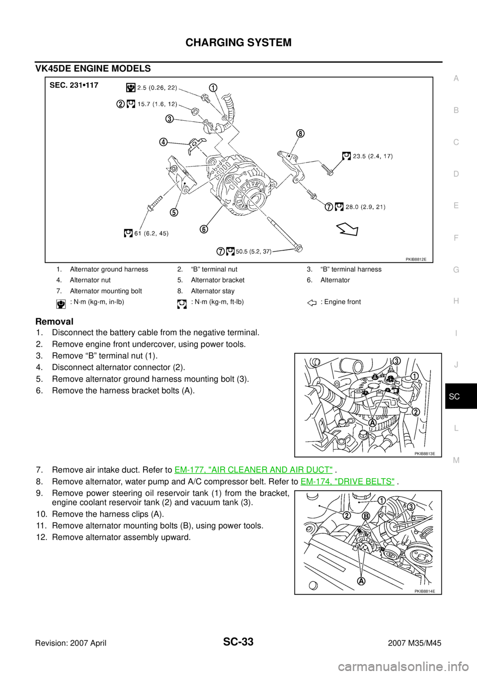
VK45DE ENGINE MODELS
Removal
1. Disconnect the battery cable from the negative terminal.
2. Remove engine front undercover, using power tools.
3. Remove “B” terminal nut (1).
4. Disconnect alternator connector (2).
5. Remove alternator ground harness mounting bolt (3).
6. Remove the harness bracket bolts (A).
7. Remove air intake duct. Refer to EM-177, "
AIR CLEANER AND AIR DUCT" .
8. Remove alternator, water pump and A/C compressor belt. Refer to EM-174, "
DRIVE BELTS" .
9. Remove power steering oil reservoir tank (1) from the bracket,
engine coolant reservoir tank (2) and vacuum tank (3).
10. Remove the harness clips (A).
11. Remove alternator mounting bolts (B), using power tools.
12. Remove alternator assembly upward.
1. Alternator ground harness 2. “B” terminal nut 3. “B” terminal harness
4. Alternator nut 5. Alternator bracket 6. Alternator
7. Alternator mounting bolt 8. Alternator stay
: N·m (kg-m, in-lb) : N·m (kg-m, ft-lb) : Engine front
PKIB8812E
PKIB8813E
PKIB8814E
Page 4195 of 4647
SC-34
CHARGING SYSTEM
Revision: 2007 April2007 M35/M45
Alternator Pulley Inspection
Perform the following.
�Make sure that alternator pulley does not rattle.
�Make sure that alternator pulley nut is tight.
Installation
Installation is the reverse order of removal.
CAUTION:
Be sure to tighten “B” terminal nut carefully.
�Install alternator, and check tension of belt. Refer to EM-174, "Checking Drive Belts" .
�For this model, the power generation voltage variable control system that controls the power generation
voltage of the alternator has been adopted. Therefore, the power generation voltage variable control sys-
tem operation inspection should be performed after replacing the alternator, and then make sure that the
system operates normally. Refer to SC-29, "
Power Generation Voltage Variable Control System Operation
Inspection" . Alternator pulley nut:
: 118 N·m (12.0 kg-m, 87 ft-lb)
Page 4196 of 4647
CHARGING SYSTEM
SC-35
C
D
E
F
G
H
I
J
L
MA
B
SC
Revision: 2007 April2007 M35/M45
Disassembly and AssemblyNKS005C1
VQ35DE ENGINE MODELS
1. Rear bearing 2. Rotor assembly 3. Retainer
4. Front bearing 5. Front bracket assembly 6. Pulley
7. Pulley nut 8. Stator assembly 9. IC voltage regulator assembly
10. Diode assembly 11. Rear bracket assembly 12. “B” terminal nut
: N·m (kg-m, in-lb) : N·m (kg-m, ft-lb) : Always replace after every dis-
assembly.
PKIB8654E
Page 4197 of 4647
SC-36
CHARGING SYSTEM
Revision: 2007 April2007 M35/M45
VK45DE ENGINE MODELS
1. Rear bearing 2. Rotor assembly 3. Retainer
4. Front bearing 5. Front bracket assembly 6. Pulley
7. Pulley nut 8. Stator assembly 9. IC voltage regulator assembly
10. Diode assembly 11. Rear bracket assembly 12. “B” terminal nut
: N·m (kg-m, in-lb) : N·m (kg-m, ft-lb) : Always replace after every dis-
assembly.
PKIB8820E
Page 4403 of 4647

SRS-22
TROUBLE DIAGNOSIS
Revision: 2007 April2007 M35/M45
Trouble Diagnosis with CONSULT-IINHS00097
DIAGNOSTIC PROCEDURE 2
Refer to GI-38, "CONSULT-II Start Procedure" .
CAUTION:
If CONSULT-II is used with no connection of CONSULT-II CONVERTER, malfunctions might be
detected in self-diagnosis depending on control unit which carry out CAN communication.
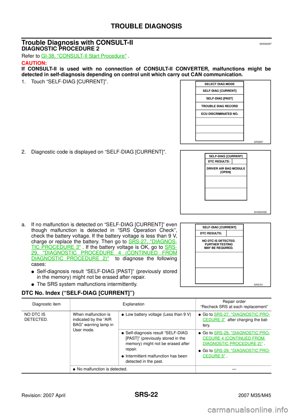
1. Touch “SELF-DIAG [CURRENT]”.
2. Diagnostic code is displayed on “SELF-DIAG [CURRENT]”.
a. If no malfunction is detected on “SELF-DIAG [CURRENT]” even
though malfunction is detected in “SRS Operation Check”,
check the battery voltage. If the battery voltage is less than 9 V,
charge or replace the battery. Then go to SRS-27, "
DIAGNOS-
TIC PROCEDURE 3" . If the battery voltage is OK, go to SRS-
29, "DIAGNOSTIC PROCEDURE 4 (CONTINUED FROM
DIAGNOSTIC PROCEDURE 2)" to diagnose the following
cases:
�Self-diagnosis result “SELF-DIAG [PAST]” (previously stored
in the memory) might not be erased after repair.
�The SRS system malfunctions intermittently.
DTC No. Index (“SELF-DIAG [CURRENT]”)
SRS697
SHIA0203E
SRS701
Diagnostic item ExplanationRepair order
“Recheck SRS at each replacement”
NO DTC IS
DETECTED.When malfunction is
indicated by the “AIR
BAG” warning lamp in
User mode.
�Low battery voltage (Less than 9 V)�Go to SRS-27, "DIAGNOSTIC PRO-
CEDURE 3" after charging the bat-
tery.
�Self-diagnosis result “SELF-DIAG
[PAST]” (previously stored in the
memory) might not be erased after
repair.
�Intermittent malfunction has been
detected in the past.
�Go to SRS-29, "DIAGNOSTIC PRO-
CEDURE 4 (CONTINUED FROM
DIAGNOSTIC PROCEDURE 2)" .
�Go to SRS-29, "DIAGNOSTIC PRO-
CEDURE 5" .
�No malfunction is detected. —
Page 4532 of 4647
AIR BREATHER HOSE
TF-43
C
E
F
G
H
I
J
K
L
MA
B
TF
Revision: 2007 April2007 M35/M45
AIR BREATHER HOSEPFP:31098
Removal and InstallationNDS000E3
Refer to the figure for air breather hose removal and installation information.
CAUTION:
�Make sure there are no pinched or restricted areas on the air breather hose caused by bending or
winding when installing it.
�Be sure to insert air breather hose to transfer tube (metal connector) until hose end reaches the
tube's base and another hose end reaches the tube bend R portion of A/T fluid charging pipe.
SDIA2408E