Page 4167 of 4647

SC-6
BATTERY
Revision: 2007 April2007 M35/M45
CHARGING THE BATTERY
CAUTION:
�Never “quick charge” a fully discharged battery.
�Keep the battery away from open flame while it is being charged.
�When connecting the charger, connect the leads first, then turn on the charger. Never turn on the
charger first, as this may cause a spark.
�If battery electrolyte temperature rises above 55 °C (131 °F), stop charging. Always charge battery
at a temperature below 55 °C (131 °F).
Charging Rates
Never charge at more than 50 ampere rate.
NOTE:
The ammeter reading on your battery charger will automatically decrease as the battery charges. This indi-
cates that the voltage of the battery is increasing normally as the state of charge improves. The charging amps
indicated above refer to initial charge rate.
�If, after charging, the specific gravity of any two cells varies more than 0.050, the battery should be
replaced.
16 (60)−0.008
10 (50)−0.012
4 (40)−0.016
−1 (30)−0.020
−7 (20)−0.024
−12 (10)−0.028
−18 (0)−0.032
Corrected specific gravity Approximate charge condition
1.260 - 1.280 Fully charged
1.230 - 1.250 3/4 charged
1.200 - 1.220 1/2 charged
1.170 - 1.190 1/4 charged
1.140 - 1.160 Almost discharged
1.110 - 1.130 Completely discharged Battery electrolyte temperature °C (°F) Add to specific gravity reading
Amps Time
50 1 hour
25 2 hours
10 5 hours
5 10 hours
Page 4172 of 4647
STARTING SYSTEM
SC-11
C
D
E
F
G
H
I
J
L
MA
B
SC
Revision: 2007 April2007 M35/M45
Trouble Diagnosis with Starting/Charging System Tester (Starting)NKS005BT
For starting system testing, use Starting/Charging System Tester (J-44373). For details and operating instruc-
tions, refer to Technical Service Bulletin.
SKIB1369E
Page 4174 of 4647

STARTING SYSTEM
SC-13
C
D
E
F
G
H
I
J
L
MA
B
SC
Revision: 2007 April2007 M35/M45
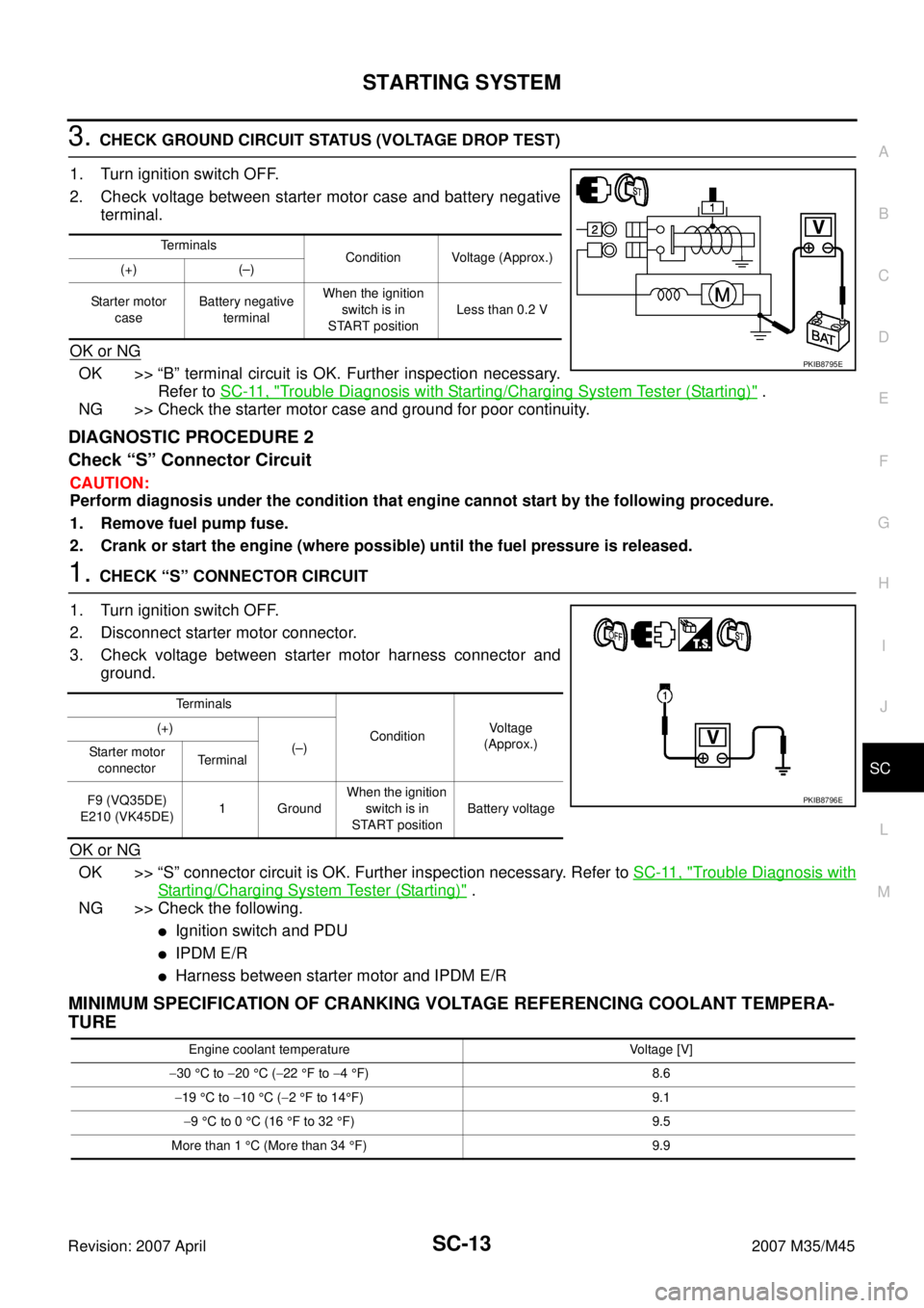
3. CHECK GROUND CIRCUIT STATUS (VOLTAGE DROP TEST)
1. Turn ignition switch OFF.
2. Check voltage between starter motor case and battery negative
terminal.
OK or NG
OK >> “B” terminal circuit is OK. Further inspection necessary.
Refer to SC-11, "
Trouble Diagnosis with Starting/Charging System Tester (Starting)" .
NG >> Check the starter motor case and ground for poor continuity.
DIAGNOSTIC PROCEDURE 2
Check “S” Connector Circuit
CAUTION:
Perform diagnosis under the condition that engine cannot start by the following procedure.
1. Remove fuel pump fuse.
2. Crank or start the engine (where possible) until the fuel pressure is released.
1. CHECK “S” CONNECTOR CIRCUIT
1. Turn ignition switch OFF.
2. Disconnect starter motor connector.
3. Check voltage between starter motor harness connector and
ground.
OK or NG
OK >> “S” connector circuit is OK. Further inspection necessary. Refer to SC-11, "Trouble Diagnosis with
Starting/Charging System Tester (Starting)" .
NG >> Check the following.
�Ignition switch and PDU
�IPDM E/R
�Harness between starter motor and IPDM E/R
MINIMUM SPECIFICATION OF CRANKING VOLTAGE REFERENCING COOLANT TEMPERA-
TURE
Terminals
Condition Voltage (Approx.)
(+) (–)
Starter motor
caseBattery negative
terminalWhen the ignition
switch is in
START positionLess than 0.2 V
PKIB8795E
Terminals
ConditionVoltage
(Approx.) (+)
(–)
Starter motor
connectorTerminal
F9 (VQ35DE)
E210 (VK45DE)1 GroundWhen the ignition
switch is in
START positionBattery voltage
PKIB8796E
Engine coolant temperature Voltage [V]
−30 °C to −20 °C (−22 °F to −4 °F) 8.6
−19 °C to −10 °C (−2 °F to 14°F) 9.1
−9 °C to 0 °C (16 °F to 32 °F) 9.5
More than 1 °C (More than 34 °F) 9.9
Page 4181 of 4647

SC-20
CHARGING SYSTEM
Revision: 2007 April2007 M35/M45
CHARGING SYSTEMPFP:23100
System Description NKS005BX
DESCRIPTION
The alternator provides DC voltage to operate the vehicle's electrical system and to keep the battery charged.
The voltage output is controlled by the IC regulator.
Power is supplied at all times
�through 10A fuse [No. 36, located in the fuse, fusible link and relay block (J/B)]
�to alternator terminal 4 (“S” terminal).
“B” terminal supplies power to charge the battery and operate the vehicle's electrical system. Output voltage is
controlled by the IC regulator at terminal 4 (“S” terminal) detecting the input voltage.
The alternator is grounded to the engine block.
With the ignition switch in the ON or START position, power is supplied
�through 10A fuse [No. 14, located in the fuse block (J/B)]
�to combination meter terminal 12 for the charge warning lamp.
Ground is supplied at signal
�to combination meter terminal 22
�through alternator terminal 3 (“L” terminal).
Then power and ground are supplied, the charge warning lamp will illuminate.
When the alternator is providing sufficient voltage with the engine running, the ground is opened and the
charge warning lamp will go off.
If the charge warning lamp illuminates with the engine running, a malfunction is indicated.
Ground is supplied
�to alternator terminal 2 (“E” terminal)
�through grounds E222, E223 and E224. (VQ35DE)
�through ground E212. (VK45DE)
MALFUNCTION INDICATOR
The IC regulator warning function activates to illuminate the charge warning lamp, if any of the following symp-
toms occur while alternator is operating:
�Excessive voltage is produced.
�No voltage is produced.
Page 4182 of 4647

CHARGING SYSTEM
SC-21
C
D
E
F
G
H
I
J
L
MA
B
SC
Revision: 2007 April2007 M35/M45
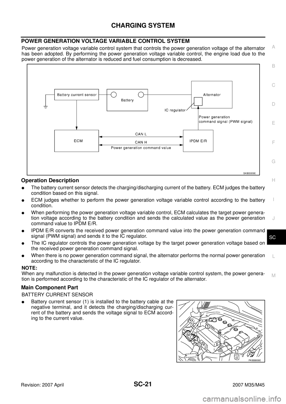
POWER GENERATION VOLTAGE VARIABLE CONTROL SYSTEM
Power generation voltage variable control system that controls the power generation voltage of the alternator
has been adopted. By performing the power generation voltage variable control, the engine load due to the
power generation of the alternator is reduced and fuel consumption is decreased.
Operation Description
�The battery current sensor detects the charging/discharging current of the battery. ECM judges the battery
condition based on this signal.
�ECM judges whether to perform the power generation voltage variable control according to the battery
condition.
�When performing the power generation voltage variable control, ECM calculates the target power genera-
tion voltage according to the battery condition and sends the calculated value as the power generation
command value to IPDM E/R.
�IPDM E/R converts the received power generation command value into the power generation command
signal (PWM signal) and sends it to the IC regulator.
�The IC regulator controls the power generation voltage by the target power generation voltage based on
the received power generation command signal.
�When there is no power generation command signal, the alternator performs the normal power generation
according to the characteristic of the IC regulator.
NOTE:
When any malfunction is detected in the power generation voltage variable control system, the power genera-
tion is performed according to the characteristic of the IC regulator of the alternator.
Main Component Part
BATTERY CURRENT SENSOR
�Battery current sensor (1) is installed to the battery cable at the
negative terminal, and it detects the charging/discharging cur-
rent of the battery and sends the voltage signal to ECM accord-
ing to the current value.
SKIB5009E
PKIB8806E
Page 4183 of 4647
SC-22
CHARGING SYSTEM
Revision: 2007 April2007 M35/M45
Wiring Diagram — CHARGE — NKS005BY
VQ35DE ENGINE MODELS (2WD)
TKWT5247E
Page 4184 of 4647
CHARGING SYSTEM
SC-23
C
D
E
F
G
H
I
J
L
MA
B
SC
Revision: 2007 April2007 M35/M45
VQ35DE ENGINE MODELS (AWD)
TKWT5248E
Page 4185 of 4647
SC-24
CHARGING SYSTEM
Revision: 2007 April2007 M35/M45
VK45DE ENGINE MODELS
TKWT5249E