Page 3000 of 4647
DOOR OUTSIDE MOLDING
EI-29
C
D
E
F
G
H
J
K
L
MA
B
EI
Revision: 2007 April2007 M35/M45
DOOR OUTSIDE MOLDING PFP:82820
Removal and InstallationNIS0024Q
FRONT DOOR OUTSIDE MOLDING
Removal
1. Fully open door window.
2. Remove door trim. Refer to EI-34, "
DOOR FINISHER" .
3. Remove front door sash cover inner. Refer to EI-36, "
FRONT DOOR SASH COVER INNER" .
4. Disconnect harness connector for tweeter (only for models with tweeter). Refer to AV- 2 7 8 , "
Tw e e t e r" .
5. Remove door mirror. Refer to GW-118, "
Removal and Installation" .
6. Disengage pawls by inserting a screwdriver to front and rear of
pawl inter grated with cap.
7. Remove door outside molding while pulling up molding using plastic spatula after disengaging.
1. Door outside molding (front) 2. Door outside molding (rear) 3. Door mirror
4. Front door outer 5. Rear door outer
PIIB2754J
PIIB4192J
Page 3001 of 4647

EI-30
DOOR OUTSIDE MOLDING
Revision: 2007 April2007 M35/M45
CAUTION:
�Be careful not to apply excessive force when removing because it is easy to deform parts.
�After removal, visually inspect molding, and if it is deformed, replace it with new molding.
Installation
Install in the reverse order of removal.
NOTE:
Molding rear end is flush with door sash rear end when installing.
REAR DOOR OUTSIDE MOLDING
Removal
1. Fully open door window.
2. Remove door trim. Refer to EI-34, "
DOOR FINISHER" .
3. Remove rear door sash cover inner. Refer to EI-36, "
REAR DOOR SASH COVER INNER" .
4. Disengage pawls by inserting a screwdriver to front and rear of pawl integrated with cap.
5. Remove door outside molding while pulling up molding using plastic spatula after disengaging.
CAUTION:
�Be careful not to apply excessive force when removing because it is easy to deform parts.
�After removal, visually inspect molding, and if it is deformed, replace it with new molding.
Installation
Install in the reverse order of removal.
NOTE:
Molding rear end is flush with door sash rear end when installing.
Page 3003 of 4647

EI-32
DOOR PARTING SEAL
Revision: 2007 April2007 M35/M45
DOOR PARTING SEALPFP:80838
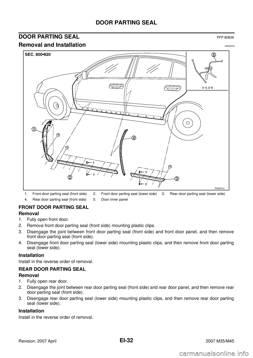
Removal and InstallationNIS0024S
FRONT DOOR PARTING SEAL
Removal
1. Fully open front door.
2. Remove front door parting seal (front side) mounting plastic clips.
3. Disengage the joint between front door parting seal (front side) and front door panel, and then remove
front door parting seal (front side).
4. Disengage front door parting seal (lower side) mounting plastic clips, and then remove front door parting
seal (lower side).
Installation
Install in the reverse order of removal.
REAR DOOR PARTING SEAL
Removal
1. Fully open rear door.
2. Disengage the joint between rear door parting seal (front side) and rear door panel, and then remove rear
door parting seal (front side).
3. Disengage rear door parting seal (lower side) mounting plastic clips, and then remove rear door parting
seal (lower side).
Installation
Install in the reverse order of removal.
1. Front door parting seal (front side) 2. Front door parting seal (lower side) 3. Rear door parting seal (lower side)
4. Rear door parting seal (front side) 5. Door inner panel
PIIB3974J
Page 3005 of 4647
EI-34
DOOR FINISHER
Revision: 2007 April2007 M35/M45
DOOR FINISHERPFP:80900
Removal and InstallationNIS0024U
FRONT AND REAR DOOR FINISHER
Removal
1. Fully open door window.
2. Remove inside handle escutcheon and remove screw.
3. Remove arm rest finisher.
4. Remove screw of armrest finisher portion.
1. Inside handle escutcheon 2. Armrest finisher 3. Front door finisher
4. Rear door finisher 5. Step lamp 6. Seat memory switch
7. Front door sash cover inner 8. Rear door sash cover inner
Clip Metal clip
PIIB4931E
Page 3007 of 4647
EI-36
DOOR FINISHER
Revision: 2007 April2007 M35/M45
FRONT DOOR SASH COVER INNER
Removal
1. Remove front door finisher.
2. Disconnect harness connector for door mirror and tweeter.
3. Remove clips of front door sash cover inner.
4. Remove front door sash cover inner.
Installation
Install in the reverse order of removal.
REAR DOOR SASH COVER INNER
Removal
1. Remove rear door finisher.
2. Remove clip of rear door sash cover inner.
3. Remove rear door sash cover inner.
Installation
Install in the reverse order of removal.
PIIB4934E
PIIB4935E
Page 3025 of 4647

EI-54
HEADLINING
Revision: 2007 April2007 M35/M45
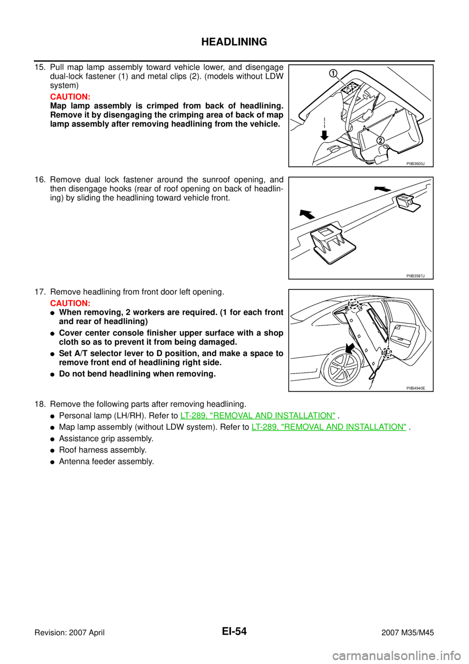
15. Pull map lamp assembly toward vehicle lower, and disengage
dual-lock fastener (1) and metal clips (2). (models without LDW
system)
CAUTION:
Map lamp assembly is crimped from back of headlining.
Remove it by disengaging the crimping area of back of map
lamp assembly after removing headlining from the vehicle.
16. Remove dual lock fastener around the sunroof opening, and
then disengage hooks (rear of roof opening on back of headlin-
ing) by sliding the headlining toward vehicle front.
17. Remove headlining from front door left opening.
CAUTION:
�When removing, 2 workers are required. (1 for each front
and rear of headlining)
�Cover center console finisher upper surface with a shop
cloth so as to prevent it from being damaged.
�Set A/T selector lever to D position, and make a space to
remove front end of headlining right side.
�Do not bend headlining when removing.
18. Remove the following parts after removing headlining.
�Personal lamp (LH/RH). Refer to LT- 2 8 9 , "REMOVAL AND INSTALLATION" .
�Map lamp assembly (without LDW system). Refer to LT- 2 8 9 , "REMOVAL AND INSTALLATION" .
�Assistance grip assembly.
�Roof harness assembly.
�Antenna feeder assembly.
PIIB3600J
PIIB3587J
PIIB4940E
Page 3185 of 4647
GI-42
LIFTING POINT
Revision: 2007 April2007 M35/M45
CAUTION:
There is canister just behind Garage jack point rear. Jack up be carefully.
Board-On Lift NAS00080
CAUTION:
Make sure vehicle is empty when lifting.
�The board-on lift attachment set at front end of vehicle
should be set on the front of the sill under the front door
opening.
�Position attachments at front and rear ends of board-on lift.
1. Safety stand point and lift up point (front) 2. Safety stand point and lift up point
(rear)3. Garage jack point (front)
4. Garage jack point (rear)
PIIB3129E
PIIB7445E
Page 3200 of 4647

GW-1
GLASSES, WINDOW SYSTEM & MIRRORS
I BODY
CONTENTS
C
D
E
F
G
H
J
K
L
M
SECTION GW
A
B
GW
Revision: 2007 April2007 M35/M45
GLASSES, WINDOW SYSTEM & MIRRORS
PRECAUTIONS .......................................................... 3
Precautions for Supplemental Restraint System
(SRS) “AIR BAG” and “SEAT BELT PRE-TEN-
SIONER” .................................................................. 3
Precautions for Procedures without Cowl Top Cover ..... 3
Handling for Adhesive and Primer ........................... 3
PREPARATION ........................................................... 4
Special Service Tools ............................................... 4
Commercial Service Tools ........................................ 4
SQUEAK AND RATTLE TROUBLE DIAGNOSES ..... 5
Work Flow ................................................................ 5
CUSTOMER INTERVIEW ..................................... 5
DUPLICATE THE NOISE AND TEST DRIVE ....... 6
CHECK RELATED SERVICE BULLETINS ........... 6
LOCATE THE NOISE AND IDENTIFY THE
ROOT CAUSE ...................................................... 6
REPAIR THE CAUSE ........................................... 6
CONFIRM THE REPAIR ....................................... 7
Generic Squeak and Rattle Troubleshooting ........... 7
INSTRUMENT PANEL .......................................... 7
CENTER CONSOLE ............................................. 7
DOORS ................................................................. 7
TRUNK .................................................................. 8
SUNROOF/HEADLINING ..................................... 8
SEATS ................................................................... 8
UNDERHOOD ....................................................... 8
Diagnostic Worksheet .............................................. 9
WINDSHIELD GLASS ...............................................11
Removal and Installation ......................................... 11
REMOVAL ............................................................ 11
INSTALLATION ................................................... 12
POWER WINDOW SYSTEM .................................... 14
Component Parts and Harness Connector Location ... 14
System Description ................................................ 14
MANUAL OPERATION ....................................... 15
AUTO OPERATION ............................................ 17
POWER WINDOW SERIAL LINK ....................... 17
POWER WINDOW LOCK ................................... 17
RETAINED POWER OPERATION ...................... 17
ANTI-PINCH SYSTEM ........................................ 18INITIALIZATION .................................................. 18
FAIL-SAFE CONTROL ........................................ 19
POWER WINDOW CONTROL BY THE KEY
CYLINDER SWITCH ........................................... 19
CAN Communication System Description .............. 19
CAN Communication Unit ....................................... 19
Schematic ............................................................... 20
Wiring Diagram — WINDOW — ............................. 21
Terminal and Reference Value for BCM ................. 27
Terminal and Reference Value for Power Window
Main Switch ............................................................ 28
Terminal and Reference Value for (Front and Rear)
Power Window Sub-Switch .................................... 29
CONSULT-II Function (BCM) ................................. 30
CONSULT-II START PROCEDURE .................... 30
WORK SUPPORT ............................................... 30
DATE MONITOR ................................................. 30
Work Flow ............................................................... 30
Trouble Diagnosis Symptom Chart ......................... 30
Check BCM Power Supply and Ground Circuit ...... 32
Check power Window Main Switch Power Supply
Circuit ..................................................................... 33
Check power Window Sub-Switch (Front Passen-
ger Side) Power Supply and Ground Circuit ........... 34
Check power Window Sub-Switch (Rear LH or RH)
Power Supply and Ground Circuit .......................... 35
Check power Window Motor (Front Driver Side) Cir-
cuit .......................................................................... 36
Check power Window Motor (Front Passenger
Side) Circuit ............................................................ 37
Check power Window Motor (Rear LH or RH) Circuit ... 38
Check encoder Circuit (Driver Side) ....................... 40
Check encoder Circuit (Passenger Side) ............... 43
Check encoder Circuit (Rear LH or RH) ................. 46
Check door Switch .................................................. 50
Check front Door Key Cylinder Switch ................... 52
Check power Window Serial Link (Passenger Side) ... 54
Check power Window Serial Link (Rear LH or RH) ... 56
Check power Window Lock Switch ......................... 56