2007 INFINITI M35 Front door
[x] Cancel search: Front doorPage 3327 of 4647

IDX-8
ALPHABETICAL INDEX
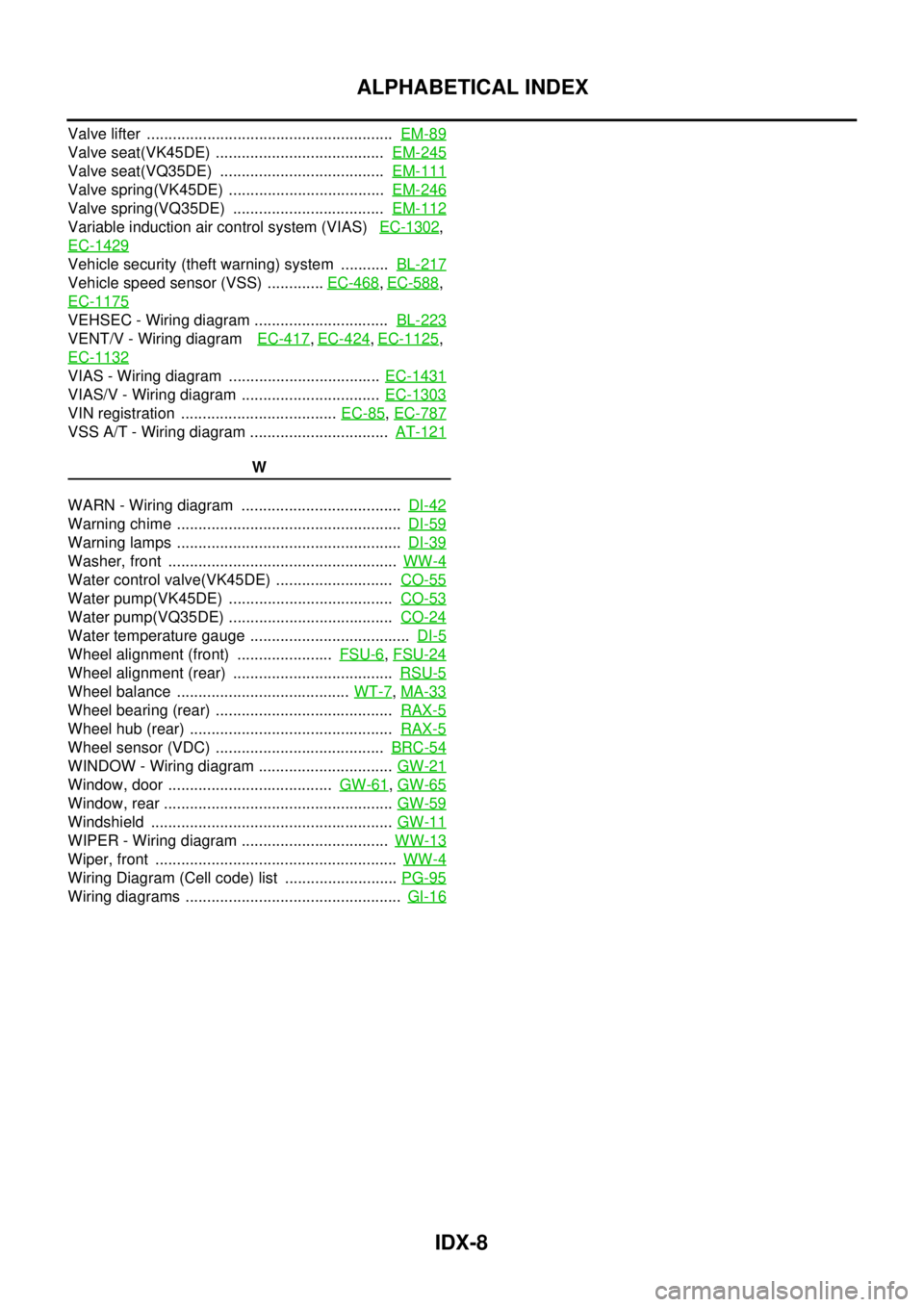
Valve lifter ......................................................... EM-89
Valve seat(VK45DE) ....................................... EM-245
Valve seat(VQ35DE) ...................................... EM-111
Valve spring(VK45DE) .................................... EM-246
Valve spring(VQ35DE) ................................... EM-112
Variable induction air control system (VIAS) EC-1302,
EC-1429
Vehicle security (theft warning) system ........... BL-217
Vehicle speed sensor (VSS) ............. EC-468, EC-588,
EC-1175
VEHSEC - Wiring diagram ............................... BL-223
VENT/V - Wiring diagram EC-417, EC-424, EC-1125,
EC-1132
VIAS - Wiring diagram ................................... EC-1431
VIAS/V - Wiring diagram ................................ EC-1303
VIN registration .................................... EC-85, EC-787
VSS A/T - Wiring diagram ................................ AT-121
W
WARN - Wiring diagram ..................................... DI-42
Warning chime .................................................... DI-59
Warning lamps .................................................... DI-39
Washer, front ..................................................... WW-4
Water control valve(VK45DE) ........................... CO-55
Water pump(VK45DE) ...................................... CO-53
Water pump(VQ35DE) ...................................... CO-24
Water temperature gauge ..................................... DI-5
Wheel alignment (front) ...................... FSU-6, FSU-24
Wheel alignment (rear) ..................................... RSU-5
Wheel balance ........................................ WT-7, MA-33
Wheel bearing (rear) ......................................... RAX-5
Wheel hub (rear) ............................................... RAX-5
Wheel sensor (VDC) ....................................... BRC-54
WINDOW - Wiring diagram ............................... GW-21
Window, door ...................................... GW-61, GW-65
Window, rear ..................................................... GW-59
Windshield ........................................................ GW-11
WIPER - Wiring diagram .................................. WW-13
Wiper, front ........................................................ WW-4
Wiring Diagram (Cell code) list .......................... PG-95
Wiring diagrams .................................................. GI-16
Page 3333 of 4647

IP-6
SQUEAK AND RATTLE TROUBLE DIAGNOSES
Revision: 2007 April2007 M35/M45
INSULATOR (Light foam block)
80845-71L00: 30 mm (1.18 in) thick, 30×50 mm (1.18×1.97 in)
FELT CLOTHTAPE
Used to insulate where movement does not occur. Ideal for instrument panel applications.
68370-4B000: 15×25 mm (0.59×0.98 in) pad/68239-13E00: 5 mm (0.20 in) wide tape roll
The following materials, not found in the kit, can also be used to repair squeaks and rattles.
UHMW (TEFLON) TAPE
Insulates where slight movement is present. Ideal for instrument panel applications.
SILICONE GREASE
Used in place of UHMW tape that will be visible or not fit. Will only last a few months.
SILICONE SPRAY
Use when grease cannot be applied.
DUCT TAPE
Use to eliminate movement.
CONFIRM THE REPAIR
Confirm that the cause of a noise is repaired by test driving the vehicle. Operate the vehicle under the same
conditions as when the noise originally occurred. Refer to the notes on the Diagnostic Worksheet.
Generic Squeak and Rattle TroubleshootingNIS0025A
Refer to Table of Contents for specific component removal and installation information.
INSTRUMENT PANEL
Most incidents are caused by contact and movement between:
1. The cluster lid A and instrument panel
2. Acrylic lens and combination meter housing
3. Instrument panel to front pillar garnish
4. Instrument panel to windshield
5. Instrument panel mounting pins
6. Wiring harnesses behind the combination meter
7. A/C defroster duct and duct joint
These incidents can usually be located by tapping or moving the components to duplicate the noise or by
pressing on the components while driving to stop the noise. Most of these incidents can be repaired by apply-
ing felt cloth tape or silicon spray (in hard to reach areas). Urethane pads can be used to insulate wiring har-
ness.
CAUTION:
Do not use silicone spray to isolate a squeak or rattle. If you saturate the area with silicone, you will
not be able to recheck the repair.
CENTER CONSOLE
Components to pay attention to include:
1. Shifter assembly cover to finisher
2. A/C control unit and cluster lid C
3. Wiring harnesses behind audio and A/C control unit
The instrument panel repair and isolation procedures also apply to the center console.
DOORS
Pay attention to the:
1. Finisher and inner panel making a slapping noise
2. Inside handle escutcheon to door finisher
3. Wiring harnesses tapping
4. Door striker out of alignment causing a popping noise on starts and stops
Tapping or moving the components or pressing on them while driving to duplicate the conditions can isolate
many of these incidents. You can usually insulate the areas with felt cloth tape or insulator foam blocks from
the Nissan Squeak and Rattle Kit (J-43980) to repair the noise.
Page 3399 of 4647
![INFINITI M35 2007 Factory Service Manual LAN-52
[CAN]
TROUBLE DIAGNOSIS
Revision: 2007 April2007 M35/M45
CAN Communication Signal ChartNKS004FV
Refer to LAN-15, "How to Use CAN Communication Signal Chart" for how to use CAN communication si INFINITI M35 2007 Factory Service Manual LAN-52
[CAN]
TROUBLE DIAGNOSIS
Revision: 2007 April2007 M35/M45
CAN Communication Signal ChartNKS004FV
Refer to LAN-15, "How to Use CAN Communication Signal Chart" for how to use CAN communication si](/manual-img/42/57024/w960_57024-3398.png)
LAN-52
[CAN]
TROUBLE DIAGNOSIS
Revision: 2007 April2007 M35/M45
CAN Communication Signal ChartNKS004FV
Refer to LAN-15, "How to Use CAN Communication Signal Chart" for how to use CAN communication signal
chart.
TYPE 1/TYPE 2/TYPE 3/TYPE 4/TYPE 5/TYPE 6/TYPE 7
NOTE:
Refer to LAN-41, "
Abbreviation List" for the abbreviations of the connecting units.
T: Transmit R: Receive
Signals
ECM
AFS
*1
BCM
LANE
*2
TCM
AV
I-KEY
M&A
STRG
TPMS
RAS
*3
PSB
ADP
ABS
ICC
*4
IPDM-E
A/C compressor request signal TR
Accelerator pedal position signal T R R R
ASCD CRUISE lamp signal T R
ASCD OD cancel request signal T R
ASCD operation signal T R
ASCD SET lamp signal T R
Battery voltage signal T R
Closed throttle position signal T R R
Cooling fan speed request signal TR
Engine coolant temperature signal T R
Engine speed signal T R R R R R R
Engine status signal T R R R
Fuel consumption monitor signal T R R
ICC brake switch signal T R
ICC prohibition signal T R
ICC steering switch signal T R
Malfunctioning indicator lamp signal T R
Power generation command value signal TR
Stop lamp switch signalTR
RT
TR
Wide open throttle position signal T R
AFS OFF indicator signal T R
A/C switch signal R T
ACC signal T R R
Blower fan motor switch signal R T
Buzzer output signalTR
TR
RT
Day time running light request signal T R
Door lock/unlock status signal T R
Door switch signal T R R R R R
Door unlock signal T R
Front fog light request signal T R R
Front wiper request signal T R R
High beam request signal T R R
Page 3402 of 4647
![INFINITI M35 2007 Factory Service Manual TROUBLE DIAGNOSIS
LAN-55
[CAN]
C
D
E
F
G
H
I
J
L
MA
B
LAN
Revision: 2007 April2007 M35/M45
TYPE 8/TYPE 9/TYPE 10/TYPE 11
NOTE:
Refer to LAN-41, "
Abbreviation List" for the abbreviations of the conne INFINITI M35 2007 Factory Service Manual TROUBLE DIAGNOSIS
LAN-55
[CAN]
C
D
E
F
G
H
I
J
L
MA
B
LAN
Revision: 2007 April2007 M35/M45
TYPE 8/TYPE 9/TYPE 10/TYPE 11
NOTE:
Refer to LAN-41, "
Abbreviation List" for the abbreviations of the conne](/manual-img/42/57024/w960_57024-3401.png)
TROUBLE DIAGNOSIS
LAN-55
[CAN]
C
D
E
F
G
H
I
J
L
MA
B
LAN
Revision: 2007 April2007 M35/M45
TYPE 8/TYPE 9/TYPE 10/TYPE 11
NOTE:
Refer to LAN-41, "
Abbreviation List" for the abbreviations of the connecting units.
T: Transmit R: Receive
Signals
ECM
4WD
AFS
*1
BCM
LANE
*2
TCM
AV
I-KEY
M&A
STRG
TPMS
PSB
ADP
ABS
ICC
*3
IPDM-E
A/C compressor request signal TR
Accelerator pedal position signal T R R R R
ASCD CRUISE lamp signal T R
ASCD OD cancel request signal T R
ASCD operation signal T R
ASCD SET lamp signal T R
Battery voltage signal T R
Closed throttle position signal T R R
Cooling fan speed request signal TR
Engine coolant temperature signal T R
Engine speed signal T R R R R R R
Engine status signal T R R R
Fuel consumption monitor signal T R R
ICC brake switch signal T R
ICC prohibition signal T R
ICC steering switch signal T R
Malfunctioning indicator lamp signal T R
Power generation command value signal TR
Snow mode switch signalTRR
RT
Stop lamp switch signalTR
RRT
TR
Wide open throttle position signal T R
AWD signal T R
AWD warning lamp signal T R
AFS OFF indicator signal T R
A/C switch signal R T
ACC signal T R R
Blower fan motor switch signal R T
Buzzer output signalTR
TR
RT
Day time running light request signal T R
Door lock/unlock status signal T R
Door switch signal T R R R R R
Door unlock signal T R
Front fog light request signal T R R
Front wiper request signal T R R
High beam request signal T R R
Page 3472 of 4647

HEADLAMP (FOR USA) - CONVENTIONAL TYPE -
LT-21
C
D
E
F
G
H
I
J
L
MA
B
LT
Revision: 2007 April2007 M35/M45
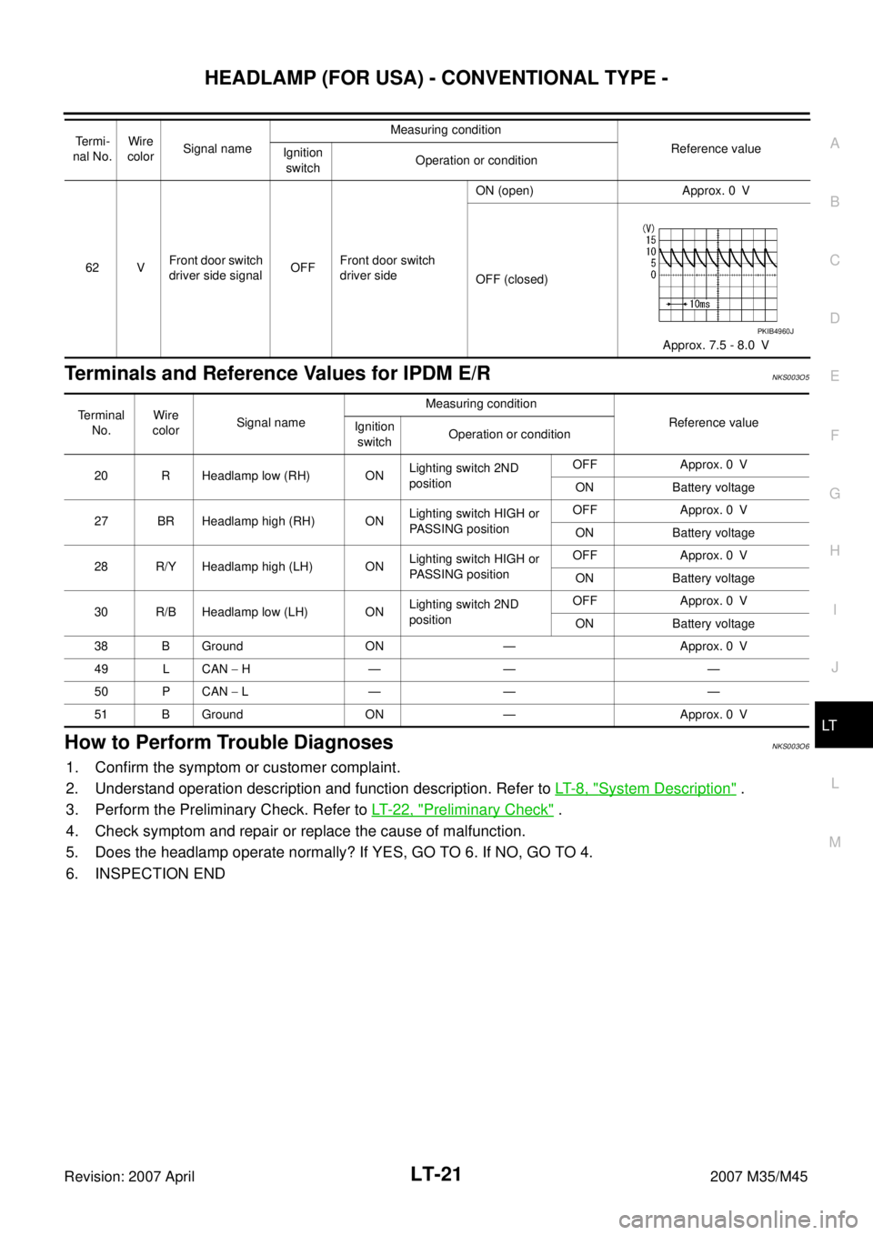
Terminals and Reference Values for IPDM E/RNKS003O5
How to Perform Trouble DiagnosesNKS003O6
1. Confirm the symptom or customer complaint.
2. Understand operation description and function description. Refer to LT- 8 , "
System Description" .
3. Perform the Preliminary Check. Refer to LT- 2 2 , "
Preliminary Check" .
4. Check symptom and repair or replace the cause of malfunction.
5. Does the headlamp operate normally? If YES, GO TO 6. If NO, GO TO 4.
6. INSPECTION END
62 VFront door switch
driver side signalOFFFront door switch
driver sideON (open) Approx. 0 V
OFF (closed)
Approx. 7.5 - 8.0 V Te r m i -
nal No.Wire
colorSignal nameMeasuring condition
Reference value
Ignition
switchOperation or condition
PKIB4960J
Terminal
No.Wire
colorSignal nameMeasuring condition
Reference value
Ignition
switchOperation or condition
20 R Headlamp low (RH) ONLighting switch 2ND
positionOFF Approx. 0 V
ON Battery voltage
27 BR Headlamp high (RH) ONLighting switch HIGH or
PASSING positionOFF Approx. 0 V
ON Battery voltage
28 R/Y Headlamp high (LH) ONLighting switch HIGH or
PASSING positionOFF Approx. 0 V
ON Battery voltage
30 R/B Headlamp low (LH) ONLighting switch 2ND
positionOFF Approx. 0 V
ON Battery voltage
38 B Ground ON — Approx. 0 V
49 L CAN − H— — —
50 P CAN − L— — —
51 B Ground ON — Approx. 0 V
Page 3475 of 4647

LT-24
HEADLAMP (FOR USA) - CONVENTIONAL TYPE -
Revision: 2007 April2007 M35/M45
NOTE:
This item is displayed, but cannot be monitored.
ACTIVE TEST
Operation Procedure
1. Touch “HEAD LAMP” on “SELECT TEST ITEM” screen.
2. Touch “ACTIVE TEST” on “SELECT DIAG MODE” screen.
3. Touch item to be tested and check operation of the selected item.
4. During the operation check, touching “BACK” deactivates the operation.
Display Item List
NOTE:
This item is displayed, but cannot be tested.HEAD LAMP SW 1 “ON/OFF”Displays status (headlamp switch 1: ON/others: OFF) of headlamp switch 1 judged from light-
ing switch signal.
HEAD LAMP SW 2 “ON/OFF”Displays status (headlamp switch 2: ON/others: OFF) of headlamp switch 2 judged from light-
ing switch signal.
TAIL LAMP SW “ON/OFF”Displays status (lighting switch 1ST or 2ND position: ON/others: OFF) of lighting switch judged
from lighting switch signal.
AUTO LIGHT SW “ON/OFF”Displays status of the lighting switch as judged from the lighting switch signal. (AUTO position:
ON/other than AUTO position: OFF)
PASSING SW “ON/OFF”Displays status (flash-to-passing switch: ON/others: OFF) of flash-to-passing switch judged
from lighting switch signal.
FR FOG SW “ON/OFF”Displays status (front fog lamp switch: ON/others: OFF) of front fog lamp switch judged from
lighting switch signal.
DOOR SW - DR “ON/OFF”Displays status of the driver door as judged from the driver door switch signal. (door is open:
ON/door is closed: OFF)
DOOR SW - AS “ON/OFF”Displays status of the passenger door as judged from the passenger door switch signal. (door
is open: ON/door is closed: OFF)
DOOR SW - RR “ON/OFF”Displays status of the rear door as judged from the rear door switch (RH) signal. (door is open:
ON/door is closed: OFF)
DOOR SW - RL “ON/OFF”Displays status of the rear door as judged from the rear door switch (LH) signal. (door is open:
ON/door is closed: OFF)
BACK DOOR SW
NOTE “OFF” —
I - KEY LOCK “ON/OFF” Displays “locked (ON)/other (OFF)” status, determined from lock signal.
OPTICAL SENSOR “0 - 5V” Displays “outside brightness (close to 5 V when light/close to 0 V when dark)” judged from
optical sensor signal.
VEHICLE SPEED “km/h” Displays vehicle speed as judged from vehicle speed signal.Monitor item Contents
Test item Description
TAIL LAMP Allows tail lamp relay to operate by switching ON-OFF.
FR FOG LAMP Allows front fog lamp relay to operate by switching ON-OFF.
DAYTIME RUNNING LIGHT
NOTE—
HEAD LAMP (HI, LO) Allows headlamp relay to operate by switching ON-OFF.
Page 3506 of 4647

HEADLAMP (FOR USA) - XENON TYPE -
LT-55
C
D
E
F
G
H
I
J
L
MA
B
LT
Revision: 2007 April2007 M35/M45
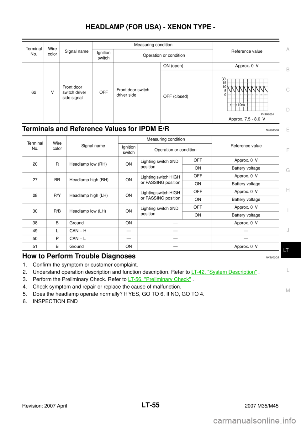
Terminals and Reference Values for IPDM E/RNKS003OR
How to Perform Trouble DiagnosesNKS003OS
1. Confirm the symptom or customer complaint.
2. Understand operation description and function description. Refer to LT- 4 2 , "
System Description" .
3. Perform the Preliminary Check. Refer to LT- 5 6 , "
Preliminary Check" .
4. Check symptom and repair or replace the cause of malfunction.
5. Does the headlamp operate normally? If YES, GO TO 6. If NO, GO TO 4.
6. INSPECTION END
62 VFront door
switch driver
side signalOFFFront door switch
driver sideON (open) Approx. 0 V
OFF (closed)
Approx. 7.5 - 8.0 V Terminal
No.Wire
colorSignal nameMeasuring condition
Reference value
Ignition
switchOperation or condition
PKIB4960J
Terminal
No.Wire
colorSignal nameMeasuring condition
Reference value
Ignition
switchOperation or condition
20 R Headlamp low (RH) ONLighting switch 2ND
positionOFF Approx. 0 V
ON Battery voltage
27 BR Headlamp high (RH) ONLighting switch HIGH
or PASSING positionOFF Approx. 0 V
ON Battery voltage
28 R/Y Headlamp high (LH) ONLighting switch HIGH
or PASSING positionOFF Approx. 0 V
ON Battery voltage
30 R/B Headlamp low (LH) ONLighting switch 2ND
positionOFF Approx. 0 V
ON Battery voltage
38 B Ground ON — Approx. 0 V
49 L CAN − H— — —
50 P CAN − L— — —
51 B Ground ON — Approx. 0 V
Page 3509 of 4647

LT-58
HEADLAMP (FOR USA) - XENON TYPE -
Revision: 2007 April2007 M35/M45
NOTE:
This item is displayed, but cannot be monitored.
ACTIVE TEST
Operation Procedure
1. Touch “HEAD LAMP” on “SELECT TEST ITEM” screen.
2. Touch “ACTIVE TEST” on “SELECT DIAG MODE” screen.
3. Touch item to be tested and check operation of the selected item.
4. During the operation check, touching “BACK” deactivates the operation.
Display Item List
NOTE:
This item is displayed, but cannot be tested.HEAD LAMP SW 1 “ON/OFF”Displays status (headlamp switch 1: ON/others: OFF) of headlamp switch 1 judged from light-
ing switch signal.
HEAD LAMP SW 2 “ON/OFF”Displays status (headlamp switch 2: ON/others: OFF) of headlamp switch 2 judged from light-
ing switch signal.
TAIL LAMP SW “ON/OFF”Displays status (lighting switch 1ST or 2ND position: ON/others: OFF) of lighting switch
judged from lighting switch signal.
AUTO LIGHT SW “ON/OFF”Displays status of the lighting switch as judged from the lighting switch signal. (AUTO position:
ON/other than AUTO position: OFF)
PASSING SW “ON/OFF”Displays status (flash-to-passing switch: ON/others: OFF) of flash-to-passing switch judged
from lighting switch signal.
FR FOG SW “ON/OFF”Displays status (front fog lamp switch: ON/others: OFF) of front fog lamp switch judged from
lighting switch signal.
DOOR SW - DR “ON/OFF”Displays status of the driver door as judged from the driver door switch signal. (door is open:
ON/door is closed: OFF)
DOOR SW - AS “ON/OFF”Displays status of the passenger door as judged from the passenger door switch signal. (door
is open: ON/door is closed: OFF)
DOOR SW - RR “ON/OFF”Displays status of the rear door as judged from the rear door switch (RH) signal. (door is
open: ON/door is closed: OFF)
DOOR SW - RL “ON/OFF”Displays status of the rear door as judged from the rear door switch (LH) signal. (door is open:
ON/door is closed: OFF)
BACK DOOR SW
NOTE “OFF” —
I - KEY LOCK “ON/OFF” Displays “locked (ON)/other (OFF)” status, determined from lock signal.
OPTICAL SENSOR “0 - 5V” Displays “outside brightness (close to 5 V when light/close to 0 V when dark)” judged from
optical sensor signal.
VEHICLE SPEED “km/h” Displays vehicle speed as judged from vehicle speed signal.Monitor item Contents
Test item Description
TAIL LAMP Allows tail lamp relay to operate by switching ON-OFF.
FR FOG LAMP Allows front fog lamp relay to operate by switching ON-OFF.
DAYTIME RUNNING LIGHT
NOTE—
HEAD LAMP (HI, LO) Allows headlamp relay to operate by switching ON-OFF.