Page 3170 of 4366
FSU-6
FRONT SUSPENSION ASSEMBLY
Revision: 2006 July 2007 FX35/FX45
FRONT SUSPENSION ASSEMBLYPFP:54010
On-Vehicle Inspection and ServiceNES000I3
Make sure the mounting conditions (looseness, back lash) of each component and component conditions
(wear, damage) are normal.
INSPECTION LOWER BALL JOINT END PLAY
1. Set front wheels in a straight-ahead position. Do not depress brake pedal.
2. Place an iron bar or similar tool between transverse link and steering knuckle.
3. Measure axial end play by prying it up and down.
CAUTION:
Be careful not to damage ball joint boot.
STRUT INSPECTION
�Check strut for oil leakage, damage and replace if there are. Refer to FSU-11, "COIL SPRING AND
STRUT" .
Wheel Alignment InspectionNES000I4
DESCRIPTION
�Measure wheel alignment under unladen conditions.
NOTE:
Unladen conditions mean that fuel, engine coolant, and lubricant are full. Spare tire, jack, hand tools and
mats are designated positions.
PRELIMINARY CHECK
�Check tires for improper air pressure and wear.
�Check road wheels for runout.
�Check wheel bearing axial end play.
�Check ball joint axial end play of compression rod, upper link, and steering knuckle
�Check shock absorber operation.
�Check each mounting part of axle and suspension for looseness and deformation.
�Check each link, rod and member for cracks, deformation and other damage.
�Check vehicle posture.
GENERAL INFORMATION AND RECOMMENDATIONS
�A four-wheel thrust alignment should be performed.
–This type of alignment is recommended for any NISSAN/INFINITI vehicle.
–The four-wheel “thrust” process helps ensure that the vehicle is properly aligned and the steering wheel is
centered.
–The alignment rack itself should be capable of accepting any NISSAN/INFINITI vehicle.
–The rack should be checked to ensure that it is level.
�Make sure the machine is properly calibrated.
–Your alignment equipment should be regularly calibrated in order to give correct information.
–Check with the manufacturer of your specific equipment for their recommended Service/Calibration
Schedule. Axial end play : 0 mm (0 in)
Page 3175 of 4366
COIL SPRING AND STRUT FSU-11
C
D
F
G H
I
J
K L
M A
B
FSU
Revision: 2006 July 2007 FX35/FX45
COIL SPRING AND STRUTPFP:55302
Removal and InstallationNES000FS
REMOVAL
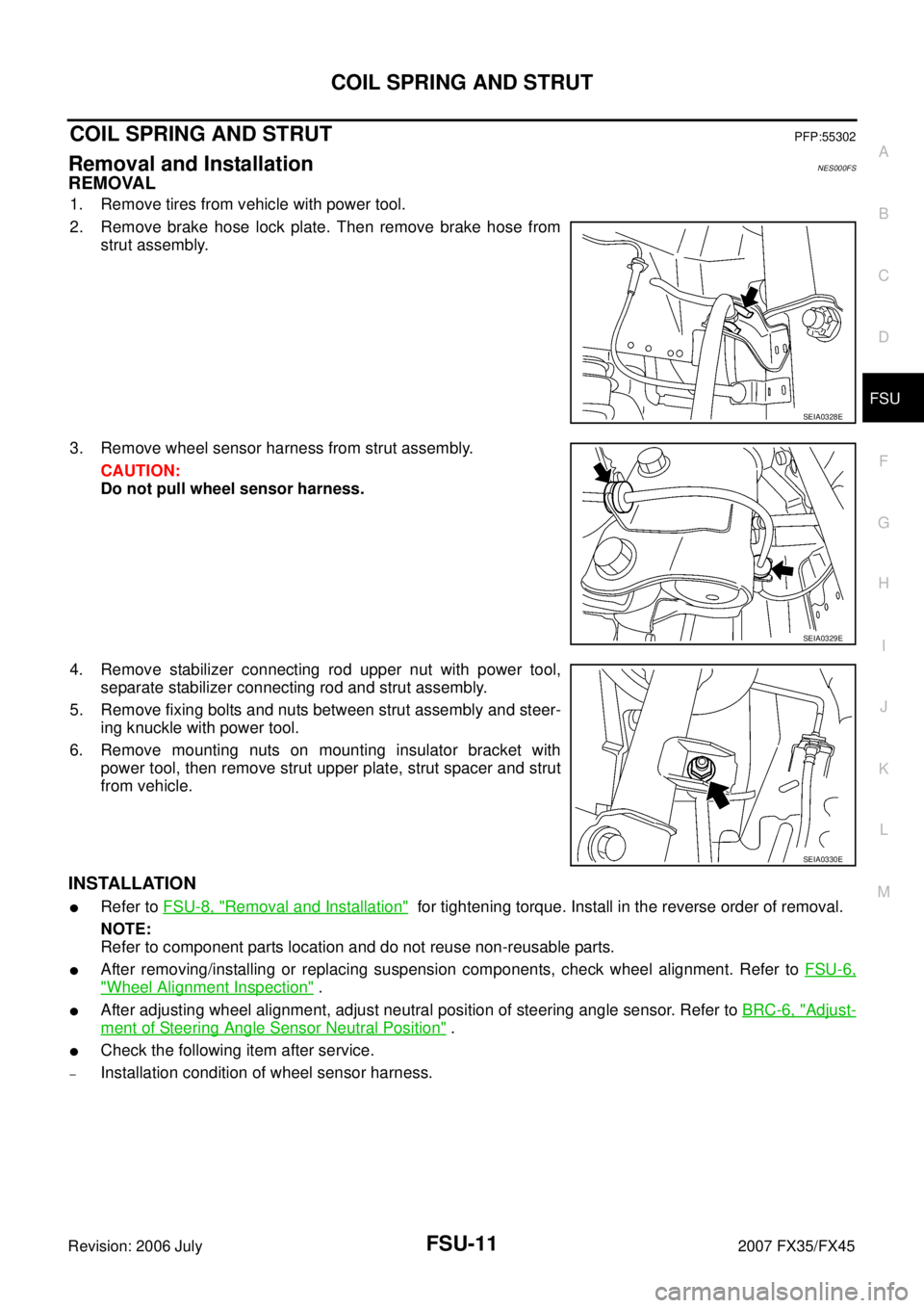
1. Remove tires from vehicle with power tool.
2. Remove brake hose lock plate. Then remove brake hose from strut assembly.
3. Remove wheel sensor harness from strut assembly. CAUTION:
Do not pull wheel sensor harness.
4. Remove stabilizer connecting rod upper nut with power tool, separate stabilizer connecting rod and strut assembly.
5. Remove fixing bolts and nuts between strut assembly and steer- ing knuckle with power tool.
6. Remove mounting nuts on mounting insulator bracket with power tool, then remove strut upper plate, strut spacer and strut
from vehicle.
INSTALLATION
�Refer to FSU-8, "Removal and Installation" for tightening torque. Install in the reverse order of removal.
NOTE:
Refer to component parts location and do not reuse non-reusable parts.
�After removing/installing or replacing suspension components, check wheel alignment. Refer to FSU-6,
"Wheel Alignment Inspection" .
�After adjusting wheel alignment, adjust neutral position of steering angle sensor. Refer to BRC-6, "Adjust-
ment of Steering Angle Sensor Neutral Position" .
�Check the following item after service.
–Installation condition of wheel sensor harness.
SEIA0328E
SEIA0329E
SEIA0330E
Page 3180 of 4366
FSU-16
STABILIZER BAR
Revision: 2006 July 2007 FX35/FX45
STABILIZER BARPFP:54611
Removal and InstallationNES000FV
REMOVAL
1. Remove tires from vehicle with power tool.
2. Remove undercover with power tool.
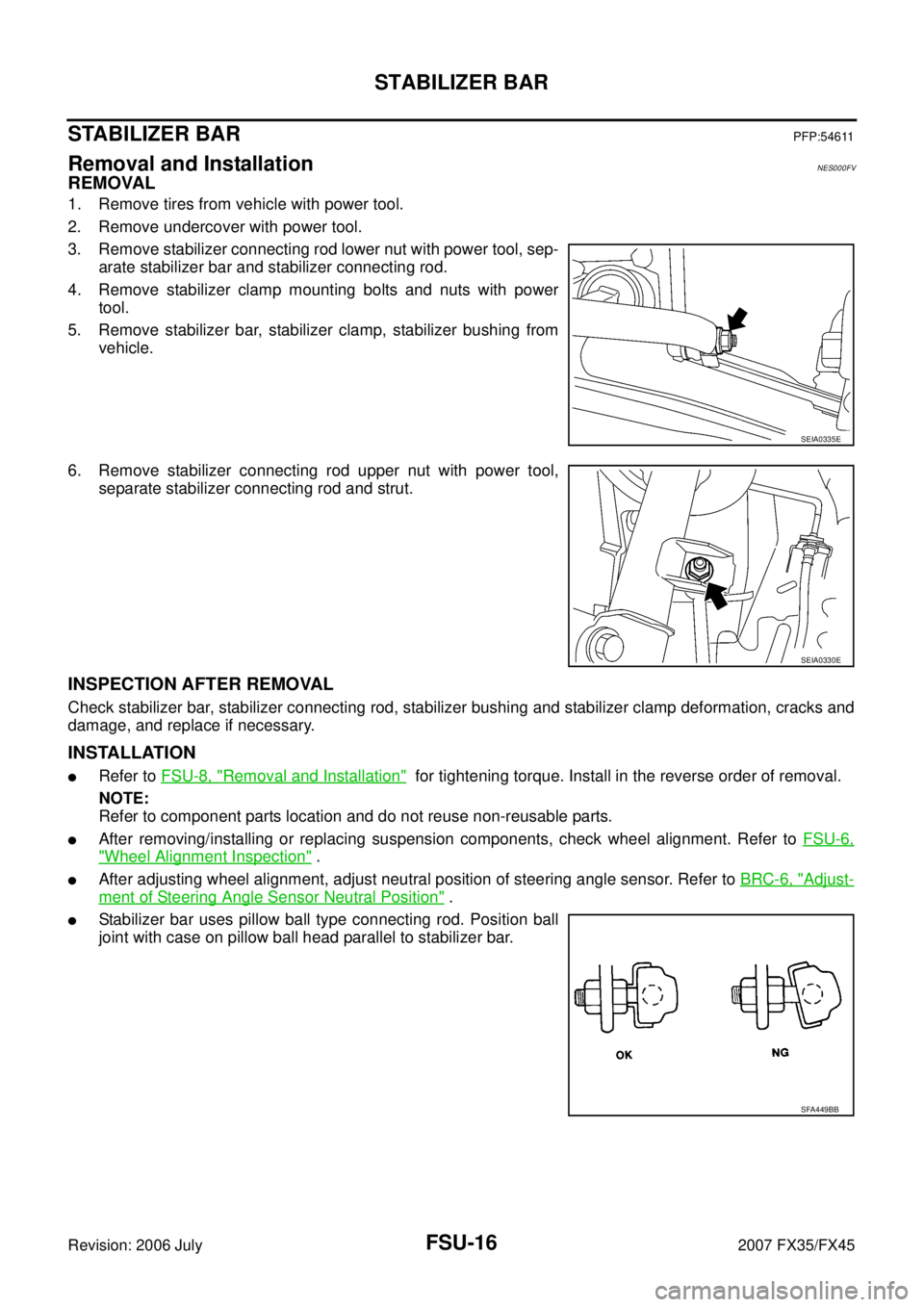
3. Remove stabilizer connecting rod lower nut with power tool, sep- arate stabilizer bar and stabilizer connecting rod.
4. Remove stabilizer clamp mounting bolts and nuts with power tool.
5. Remove stabilizer bar, stabilizer clamp, stabilizer bushing from vehicle.
6. Remove stabilizer connecting rod upper nut with power tool, separate stabilizer connecting rod and strut.
INSPECTION AFTER REMOVAL
Check stabilizer bar, stabilizer connecting rod, stabilizer bushing and stabilizer clamp deformation, cracks and
damage, and replace if necessary.
INSTALLATION
�Refer to FSU-8, "Removal and Installation" for tightening torque. Install in the reverse order of removal.
NOTE:
Refer to component parts location and do not reuse non-reusable parts.
�After removing/installing or replacing suspension components, check wheel alignment. Refer to FSU-6,
"Wheel Alignment Inspection" .
�After adjusting wheel alignment, adjust neutral position of steering angle sensor. Refer to BRC-6, "Adjust-
ment of Steering Angle Sensor Neutral Position" .
�Stabilizer bar uses pillow ball type connecting rod. Position ball
joint with case on pillow ball head parallel to stabilizer bar.
SEIA0335E
SEIA0330E
SFA449BB
Page 3181 of 4366
FRONT SUSPENSION MEMBER FSU-17
C
D
F
G H
I
J
K L
M A
B
FSU
Revision: 2006 July 2007 FX35/FX45
FRONT SUSPENSION MEMBERPFP:54401
Removal and InstallationNES000FW
REMOVAL
1. Set engine slinger to engine, then suspend an engine.
2. Remove tires from vehicle with power tool.
3. Remove undercover with power tool.
4. Remove front cross bar.
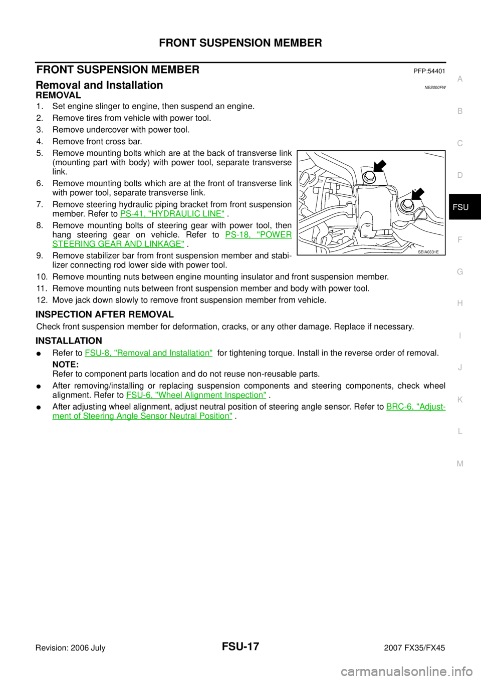
5. Remove mounting bolts which are at the back of transverse link (mounting part with body) with power tool, separate transverse
link.
6. Remove mounting bolts which are at the front of transverse link with power tool, separate transverse link.
7. Remove steering hydraulic piping bracket from front suspension member. Refer to PS-41, "
HYDRAULIC LINE" .
8. Remove mounting bolts of steering gear with power tool, then hang steering gear on vehicle. Refer to PS-18, "
POWER
STEERING GEAR AND LINKAGE" .
9. Remove stabilizer bar from front suspension member and stabi- lizer connecting rod lower side with power tool.
10. Remove mounting nuts between engine mounting insulator and front suspension member.
11. Remove mounting nuts between front suspension member and body with power tool.
12. Move jack down slowly to remove front suspension member from vehicle.
INSPECTION AFTER REMOVAL
Check front suspension member for deformation, cracks, or any other damage. Replace if necessary.
INSTALLATION
�Refer to FSU-8, "Removal and Installation" for tightening torque. Install in the reverse order of removal.
NOTE:
Refer to component parts location and do not reuse non-reusable parts.
�After removing/installing or replacing suspension components and steering components, check wheel
alignment. Refer to FSU-6, "
Wheel Alignment Inspection" .
�After adjusting wheel alignment, adjust neutral position of steering angle sensor. Refer to BRC-6, "Adjust-
ment of Steering Angle Sensor Neutral Position" .
SEIA0331E
Page 3184 of 4366
GI-2Revision: 2006 July 2007 FX35/FX45
TIGHTENING TORQUE OF STANDARD BOLTS .
... 47
Tightening Torque Table ...................................... ... 47
RECOMMENDED CHEMICAL PRODUCTS AND
SEALANTS ............................................................ ... 48
Recommended Chemical Products and Sealants ... 48
IDENTIFICATION INFORMATION ......................... ... 49
Model Variation .................................................... ... 49
IDENTIFICATION NUMBER ............................. ... 50 IDENTIFICATION PLATE .................................
... 50
ENGINE SERIAL NUMBER .............................. ... 51
AUTOMATIC TRANSMISSION NUMBER ........ ... 51
Dimensions .......................................................... ... 51
Wheels & Tires ..................................................... ... 51
TERMINOLOGY ..................................................... ... 52
SAE J1930 Terminology List ................................ ... 52
Page 3227 of 4366
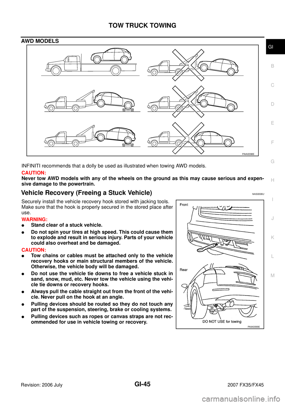
TOW TRUCK TOWING GI-45
C
D E
F
G H
I
J
K L
M B
GI
Revision: 2006 July 2007 FX35/FX45
AWD MODELS
INFINITI recommends that a dolly be used as illustrated when towing AWD models.
CAUTION:
Never tow AWD models with any of the wheels on the ground as this may cause serious and expen-
sive damage to the powertrain.
Vehicle Recovery (Freeing a Stuck Vehicle) NAS0006U
Securely install the vehicle recovery hook stored with jacking tools.
Make sure that the hook is properly secured in the stored place after
use.
WARNING:
�Stand clear of a stuck vehicle.
�Do not spin your tires at high speed. This could cause them
to explode and result in serious injury. Parts of your vehicle
could also overheat and be damaged.
CAUTION:
�Tow chains or cables must be attached only to the vehicle
recovery hooks or main structural members of the vehicle.
Otherwise, the vehicle body will be damaged.
�Do not use the vehicle tie downs to free a vehicle stuck in
sand, snow, mud, etc. Never tow the vehicle using the vehi-
cle tie downs or recovery hooks.
�Always pull the cable straight out from the front of the vehi-
cle. Never pull on the hook at an angle.
�Pulling devices should be routed so they do not touch any
part of the suspension, steering, brake or cooling systems.
�Pulling devices such as ropes or canvas straps are not rec-
ommended for use in vehicle towing or recovery.
PAIA0098E
PAIA0099E
Page 3228 of 4366

GI-46
TOW TRUCK TOWING
Revision: 2006 July 2007 FX35/FX45
AUTOMATIC TRANSMISSION
To tow a vehicle equipped with an automatic transmission, an appropriate vehicle dolly MUST be placed
under the towed vehicle's drive wheels. Always follow the dolly manufacture's recommendations when using
their product.
If the vehicle is stuck in sand, snow, mud, etc., use the following procedure:
1. Turn off the Vehicle Dynamic Control System.
2. Make sure the area in front and behind the vehicle is clear of obstructions.
3. Turn the steering wheel right and left to clear an area around the front tires.
4. Slowly rock the vehicle forward and backward. Shift back and forth between R (reverse) and D (drive).
Apply the accelerator as little as possible to maintain the rocking motion.
Release the accelerator pedal before shifting between R and D.
Do not spin the tires above 35 mph (55 km/h).
5. If the vehicle can not be freed after a few tries, contact a professional towing service to remove the vehi- cle.
Page 3233 of 4366
IDENTIFICATION INFORMATION GI-51
C
D E
F
G H
I
J
K L
M B
GI
Revision: 2006 July 2007 FX35/FX45
ENGINE SERIAL NUMBER
AUTOMATIC TRANSMISSION NUMBER
Dimensions NAS0006Y
Unit: mm (in)
Wheels & Tires NAS0006Z
PAIA0110E
PA I A 0 111 E
PAIA0054E
Overall length 4,803 (189.1)
Overall width 1,925 (75.8)
Overall height 1,672.6 (65.9)
Front tread 1,592 (62.7)
Rear tread 1,642 (64.6)
Wheelbase 2,850 (112.2)
Application Conventional Spare
Road wheel/offset mm (in) 18 X 8JJ Aluminum/40 (1.57)
20 X 8JJ Aluminum/40 (1.57) T175/90D18 110M
Tire size P265/60R18 109V
P265/50R20 106V