Page 1133 of 1226

308-0343 Manual TransmissionlTransaxle 308-03-43
DISASSEMBLY AND ASSEMBLY OF SUBASSEMBLIES
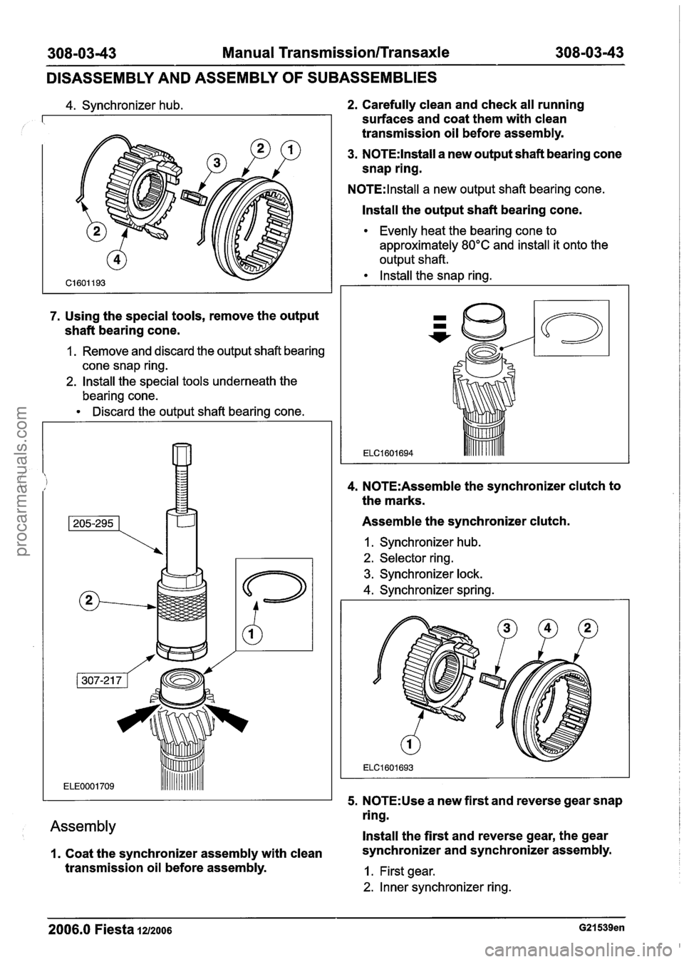
4. Synchronizer hub.
7. Using the special tools, remove the output
shaft bearing cone.
1. Remove and discard the output shaft bearing
cone snap ring.
2. Install the special tools underneath the
bearing cone.
Discard the output shaft bearing cone.
Assembly
I. Coat the synchronizer assembly with clean
transmission oil before assembly.
2. Carefully clean and check all running
surfaces and coat them with clean
transmission oil before assembly.
3. N0TE:lnstall a new output shaft bearing cone
snap ring.
N0TE:lnstall a new output shaft bearing cone.
Install the output shaft bearing cone.
Evenly heat the bearing cone to
approximately
80°C and install it onto the
output shaft.
Install the snap ring.
4. N0TE:Assemble the synchronizer clutch to
the marks.
Assemble the synchronizer clutch.
I. Synchronizer hub.
2. Selector ring.
3. Synchronizer lock.
4. Synchronizer spring.
5.
N0TE:Use a new first and reverse gear snap
ring.
Install the first and reverse gear, the gear
synchronizer and synchronizer assembly.
1. First gear.
2. Inner synchronizer ring.
2006.0 Fiesta 1212006 G21539en
procarmanuals.com
Page 1140 of 1226
308-03-50 Manual Transmission/Transaxle 308-03-50
DISASSEMBLY AND ASSEMBLY OF SUBASSEMBLIES
Selector Plate(l6 284 8)
Overview, selector mechanism
1 2 1 Selector plate I
Item Description 5. Fifth and reverse gear selector shaft guide
1 4 1 Selector shaft interlock mechanism I
1
1 5 1 Selector shaft I
Fifth and reverse gear selector shaft guide
1 6- 1 Reverse gear selector lever return sleeve.
sleeve
1 7 1 Reverse gear selector lever I
Disassembly
1. Remove the selector mechanism.
8
9
1. Fifth and reverse gear selector shaft.
2. Selector shaft.
3. Reverse gear selector lever .
Snap-ring
Fifth and reverse gear selector shaft
4. Selector plate.
Assembly
1, Install the selector mechanism.
1 . Selector shaft.
2. Reverse gear selector lever.
3. Fifth and reverse gear selector shaft guide
sleeve.
-- - - - -- --
2006.0 Fiesta 1212006 G18lllen
procarmanuals.com
Page 1143 of 1226
308-03-53 Manual Transmission/Transaxle 308-03-53
ASSEMBLY
*' ACAUTION:M~~~ sure the output shaft 2. lnstall the fifth and reverse gear selector
roller bearing is installed with the scribed shaft.
text uppermost.
Using the special tool, install the output shaft
roller bearing and the output shaft bearing
cup.
1. lnstall the oil funnel.
2. lnstall the output shaft roller bearing.
3. Using the special tool, install the differential
bearing cup.
4, lnstall the fifth and reverse gear selector
shaft, and the shift lock.
1, lnstall the shift lock.
5. lnstall the reverse gear idler.
6. lnstall the differential assembly and the
permanent magnet.
7. Prepare the input and output shaft for
installation.
1. Engage the input shaft and output shaft.
2. Move the first and second gear shift forks to
the installation position.
2006.0 Fiesta 1212006 G23119en
procarmanuals.com
Page 1144 of 1226

308-03-54 Manual Transmission/Transaxle 308-0344
ASSEMBLY
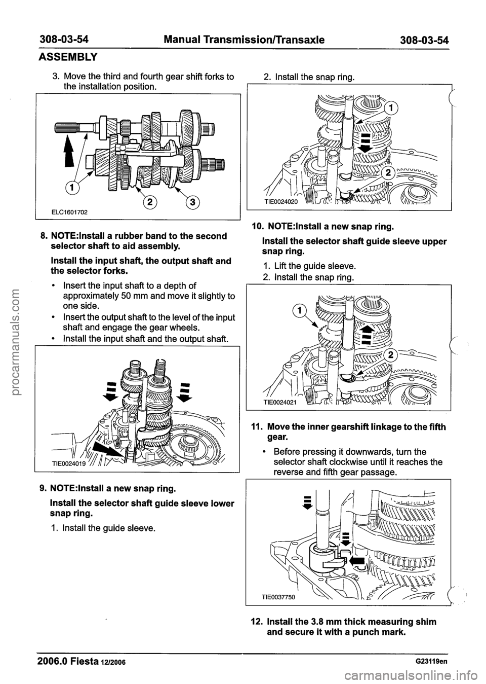
3. Move the third and fourth gear shift forks to
the installation position.
8. N0TE:lnstall a rubber band to the second
selector shaft to aid assembly.
2. lnstall the snap ring.
10. N0TE:lnstall a new snap ring.
lnstall the selector shaft guide sleeve upper
snap ring.
- lnstall the input shaft, the output shaft and
the selector forks. 1. Lift the guide sleeve.
2. lnstall the snap rina.
Insert the input shaft to a depth of I
approximately 50 mm and move it slightly to
one side.
Insert the output shaft to the level of the input
shaft and engage the gear wheels.
lnstall the input shaft and the output shaft.
9. N0TE:lnstall a new snap ring.
lnstall the selector shaft guide sleeve lower
snap ring.
1. lnstall the guide sleeve.
11. Move the inner gearshift linkage to the fifth
gear.
Before pressing it downwards, turn the
selector shaft clockwise until it reaches the
reverse and fifth gear passage.
12. lnstall the 3.8 mm thick measuring shim
and secure
it with a punch mark.
2006.0 Fiesta 1212006 G23119en
procarmanuals.com
Page 1148 of 1226
308-03-58 Manual Transmission/Transaxle 308-03-58
ASSEMBLY
29. N0TE:The transaxle housing must not Correct installation position for the selector
contact the press table. Support the input shaft interlock mechanism.
shaft splines.
Using the special tool and a suitable press,
install the fifth gear.
33. Install the selector shaft interlock
mechanism.
Apply sealant to the thread.
30. Mount the transaxle on the mounting stand.
31. N0TE:lnstall a new fifth gear snap ring.
Install the fifth gear snap ring.
1. Install the snap ring onto the special tool.
2. Install the special tool and push on the snap
ring.
34. N0TE:Align the gear synchronizer to the
marks.
Assemble the fifth gear synchronizer.
I. Fifth gear.
2. Synchronizer ring.
3. Synchronizer assembly.
32. Make sure that the selector shaft is in the 4. Retaining plate.
neutral position.
2006.0 Fiesta 1212006 G23119en
procarmanuals.com
Page 1149 of 1226
308-03-59 Manual Transmission/Transaxle 308-03-59
ASSEMBLY
35. N0TE:lnstall a new fifth gear synchronizer
assembly snap ring.
1 , N0TE:Use a new selector fork retaining pin.
lnstall the fifth gear synchronizer assembly
and the selector fork.
lnstall the retaining pin.
lnstall the snap ring.
36. Apply sealer evenly to the inside edge of
the fifth gear housing mating face.
37. lnstall the fifth gear housing cover.
38. lnstall the selector lever.
lnstall the bellows.
39. Engage the fifth gear.
Turn the selector shaft clockwise as far as
possible and push the shaft in.
40. N0TE:lnstall new halfshaft oil seals.
Using the special tools, install both halfshaft
oil seals (left-hand side shown).
2006.0 Fiesta 1212006 G23119en
procarmanuals.com
Page 1154 of 1226

308-03-64 Manual Transmission/Transaxle 308-03-64
INSTALLATION
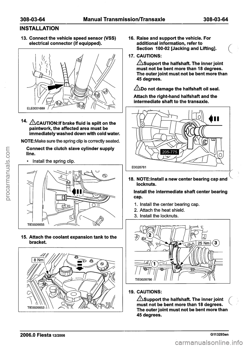
13. Connect the vehicle speed sensor (VSS) 16. Raise and support the vehicle. For
electrical connector (if equipped). additional information, refer to
Section 100-02 [Jacking and Lifting].
17. CAUTIONS:
Asupport the halfshaft. The inner joint
must not be bent more than 18 degrees.
The outer joint must not be bent more than
45 degrees.
ADO not damage the halfshaft oil seal.
Attach the right-hand halfshaft and the
intermediate shaft to the transaxle.
14' ACAUTION:~~ brake fluid is spilt on the
paintwork, the affected area must be
immediately washed down with cold water.
N0TE:Make sure the spring clip is correctly seated.
Connect the clutch slave cylinder supply
line.
Install the spring clip.
15. Attach the coolant expansion tank to the
bracket. 18.
N0TE:lnstall a
new center bearing cap and
locknuts.
Install the intermediate shaft center bearing
cap.
I. Install the center bearing cap.
2. Attach the heat shield.
3. Install the locknuts.
19. CAUTIONS:
Asupport the halfshaft. The inner joint
must not be bent more than 18 degrees.
The outer joint must not be bent more than
45 degrees.
2006.0 Fiesta 1212006 GI I 3293en
procarmanuals.com
Page 1155 of 1226
308-03-65 Manual Transmission/Transaxle 308-03-65
INSTALLATION
ADO not damage the halfshaft oil seal. 21. Install the engine support insulator.
/ / AMake sure the snap ring is correctly
seated.
N0TE:lnstall a new snap ring.
Attach the left-hand halfshaft to the
transaxle.
20m ACAUTION:M~~~ sure that the heat shield
is installed to prevent damage to the ball
joint.
N0TE:The lower arm pinch bolt must be installed ' ' from the rear of the wheel knuckle.
22. Install the accessory drive belt cover.
Attach the lower arm to the wheel knuckle
on both sides.
Vehicles without automated gearshift
23. Attach the gearshift cables to the bracket
and turn the abutment sleeves
counterclockwise.
2006.0 Fiesta 1212006 GI 13293en
procarmanuals.com