Page 1162 of 1226
308-03-72 Manual Transmission/Transaxle 308-03-72
INSTALLATION
20. Attach the gearshift cables to the bracket 23. Connect the reversing lamp switch
and turn the abutment sleeves electrical connector.
counterclockwise.
I I
24. Install the starter motor.
21. Attach the gearshift cables to the selector
levers.
22. Install the gearshift cables cover. 25.
Install the wiring harness retaining bracket. Attach the wiring harness to the retaining
bracket.
26. Lower the vehicle.
2006.0 Fiesta 1212006 G453417en
procarmanuals.com
Page 1171 of 1226
Manual Transmission/Transaxle External
Controls
REMOVAL AND INSTALLATION
Gearshift Lever(l6 524 0)
Removal
I. Remove the gearshift lever trim panel.
Disconnect the cigar lighter electrical
connector.
2. Detach the gearshift cables from the
gearshift lever.
4. Remove the gearshift lever front retaining
bolts.
5. Remove the gearshift lever.
Remove the bolts.
Installation
1. To install, reverse the removal procedure. 3. Detach the gearshift cables from the
retaining bracket. 2. Adjust the gearshift cables. For additional
information, refer to Section
308-00 [Manual Turn the abutment sleeves clockwise. Transmission/Transaxle and Clutch - General
Information].
2006.0 Fiesta 1212006 GI 86744en
procarmanuals.com
Page 1172 of 1226
Manual Transmission/Transaxle External
308-06-8 Controls 308-06-8
REMOVAL AND INSTALLATION
Gearshift Cables(l6 575 0)
Removal 6. Remove the gearshift cables cover.
I. Remove the gearshift lever.
For additional information, refer to Gearshift
Lever in this section.
2. Remove the air cleaner. For additional
information, refer to Section
303-12 [Intake
Air Distribution and Filtering].
3. Raise and support the vehicle. For additional
information, refer to Section
100-02 [Jacking
and Lifting].
4. Remove the exhaust front hanger insulator.
5. Detach the exhaust heat shield from the floor
panel.
Slide the heat shield backwards.
7. Detach the gearshift cables from the
transaxle.
I. Detach the gearshift cable and the selector
cable from the selector levers.
2. Turn the abutment sleeves clockwise and
detach the cables from the bracket.
8. Detach the gearshift cables from the
retaining clip.
2006.0 Fiesta 1212006 GI 86745en
procarmanuals.com
Page 1174 of 1226
Manual Transmission/Transaxle External
308-06-1 0 Controls 308-06-1 0
REMOVAL AND INSTALLATION
3. Raise and support the vehicle. For additional 7. Install the exhaust front hanger insulator.
information, refer to Section
100-02 [Jacking
and Lifting].
4. Attach the gearshift cables to the bracket
and turn the abutment sleeves
counterclockwise.
6. Attach the exhaust heat shield to the floor
panel.
Slide the heat shield forwards. 8.
Attach
the gearshift cables to the retaining
clip.
9. Attach the selector cable to the retaining clip.
10. Install the gearshift lever.
For additional information, refer to
Gearshift Lever in this section.
11. Install the air cleaner. For additional
information, refer to Section
303-12 [Intake (
Air Distribution and Filtering].
2006.0 Fiesta 1212006 GI 86745en
procarmanuals.com
Page 1178 of 1226

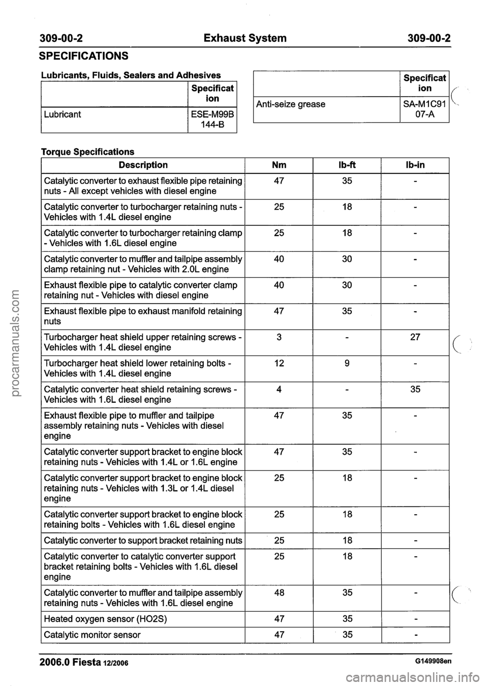
309-00-2 Exhaust System 309-00-2
SPECIFICATIONS
Lubricants. Fluids. Sealers and Adhesives I Specificat I
Specificat
I ion I
I ion I/- ,
Anti-seize grease I SA-MI C91 I 'c-
Lubricant
Torque Specifications
I Description I Nm I Ibf I Ib-in I
Catalytic converter to exhaust flexible pipe retaining
nuts
- All except vehicles with diesel engine
Catalytic converter to turbocharger retaining nuts
-
Vehicles with I .4L diesel engine
Catalytic converter to turbocharger retaining clamp
- Vehicles with 1.6L diesel engine
Catalytic converter to muffler and tailpipe assembly
clamp retaining nut
- Vehicles with 2.OL engine
Exhaust flexible pipe to catalytic converter clamp
retaining nut
- Vehicles with diesel engine
Exhaust flexible pipe to exhaust manifold retaining
1 nuts
Turbocharger heat shield upper retaining screws
-
Vehicles with I .4L diesel engine
Turbocharger heat shield lower retaining bolts
-
Vehicles with I .4L diesel engine
Catalytic converter heat shield retaining screws
-
Vehicles with I .6L diesel engine
Exhaust flexible pipe to muffler and tailpipe
assembly retaining nuts
- Vehicles with diesel
engine
Catalytic converter support bracket to engine block
retaining nuts
- Vehicles with 1.4L or 1.6L engine
Catalytic converter support bracket to engine block
retaining nuts
- Vehicles with 1.3L or 1.4L diesel
engine
Catalytic converter support bracket to engine block retaining bolts
- Vehicles with I .6L diesel engine
I Catalytic converter to support bracket retaining nuts I 25 I 18 I - 1
Catalytic converter to catalytic converter support
bracket retaining bolts
- Vehicles with 1.6L diesel
engine
Catalytic converter to muffler and tailpipe assembly
retaining nuts
- Vehicles with 1.6L diesel engine
I Heated oxygen sensor (H02S) I 47 I 35 I - I
I Catalytic monitor sensor I 47 I 35 I - I
2006.0 Fiesta 1212006 G149908en
procarmanuals.com
Page 1191 of 1226

31 0-00-5 Fuel System - General Information 31 0-00-5
GENERAL PROCEDURES
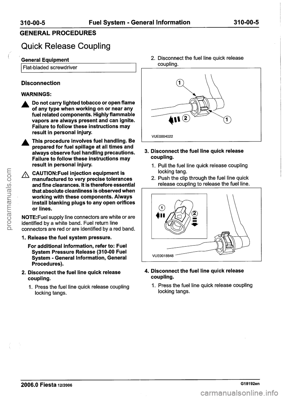
Quick Release Coupling
i 1 General Equipment 2. Disconnect the fuel line quick release
coupling.
Flat-bladed screwdriver
Disconnection
WARNINGS:
A Do not carry lighted tobacco or open flame
of any type when working on or near any
fuel related components. Highly flammable
vapors are always present and can ignite.
Failure to follow these instructions may
result in personal injury.
A This procedure involves fuel handling. Be
prepared for fuel spillage at all times and
always observe fuel handling precautions.
Failure to follow these instructions may
result in personal injury. 3.
Disconnect the fuel line quick release
coupling.
1. Pull the fuel line quick release coupling
CAUTI0N:Fuel injection equipment is locking tang.
manufactured to very precise tolerances 2. Push the clip through the fuel line quick
and fine clearances. It is therefore essential release coupling to release the fuel line.
that absolute cleanliness is observed when I
i
working with these components. Always
install blanking plugs to any open orifices
or lines.
N0TE:Fuel supply line connectors are white or are
identified by a white band. Fuel return line
connectors are red or are identified by a red band.
1. Release the fuel system pressure.
For additional information, refer to: Fuel
System Pressure Release (31
0-00 Fuel
Svstem - General Information, General
2. Disconnect the fuel line quick release 4. Disconnect the fuel line quick release
coupling. coupling.
1. Press the fuel line quick release coupling 1. Press the fuel line quick release coupling
locking tangs. locking tangs.
2006.0 Fiesta 1212006 GI 81 92en
procarmanuals.com
Page 1192 of 1226
31 0-00-6 Fuel System - General Information 31 0-00-6
GENERAL PROCEDURES
5. Disconnect the fuel line quick release
coupling.
2. Disconnect the fuel line quick release 7. Disconnect the fuel tank vent line quick
coupling. release coupling.
8. Release the fuel line quick release coupling.
-
4 =
b
.-
VUE0014718
- - Press the fuel line quick release coupling
Press the fuel line quick release coupling
locking release collar.
buttons and pull the fuel line to disconnect.
63
E38211
9. Disconnect the fuel line quick release 6. Release the fuel tank vent line quick release
coupling.
Press the fuel tank vent line quick release
coupling locking release collar.
2006.0 Fiesta 1212006 GI 81 92en
procarmanuals.com
Page 1193 of 1226

31 0-00-7 Fuel System - General Information 31 0-00-7
GENERAL PROCEDURES
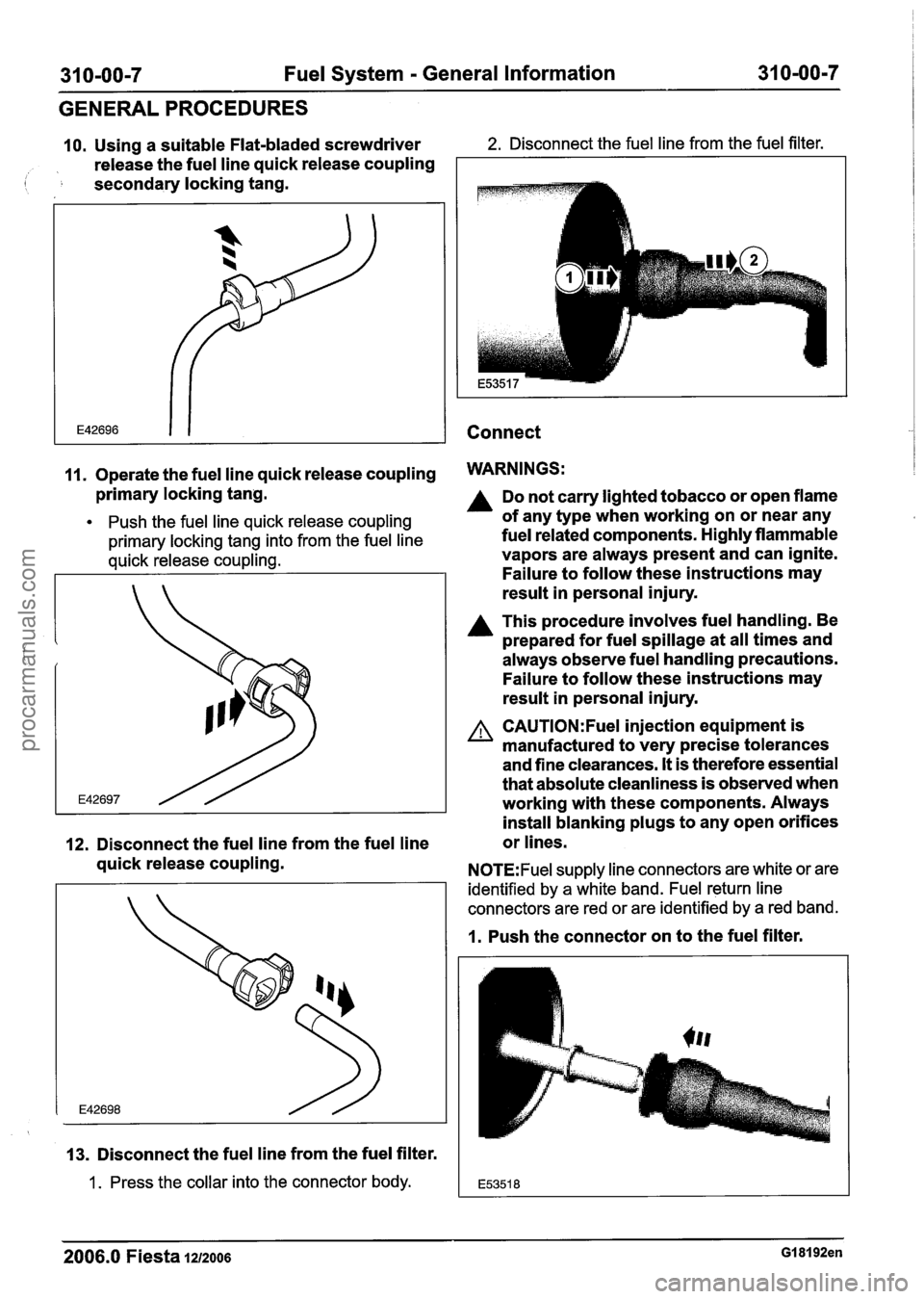
10. Using a suitable Flat-bladed screwdriver 2. Disconnect the fuel line from the fuel filter.
release the fuel line quick release coupling
( secondary locking tang.
Connect
11. Operate the fuel line quick release coupling WARNINGS:
primary locking tang.
Push the fuel line quick release coupling
primary locking tang into from the fuel line
quick release coupling.
12. Disconnect the fuel line from the fuel line
quick release coupling.
13. Disconnect the fuel line from the fuel filter.
1 . Press the collar into the connector body.
Do not carry lighted tobacco or open flame
of any type when working on or near any
fuel related components. Highly flammable
vapors are always present and can ignite.
Failure to follow these instructions may
result in personal injury.
A This procedure involves fuel handling. Be
prepared for fuel spillage at all times and
always observe fuel handling precautions.
Failure to follow these instructions may
result in personal injury.
A CAUTI0N:Fuel injection equipment is
manufactured to very precise tolerances
and fine clearances.
It is therefore essential
that absolute cleanliness is observed when
working with these components. Always
install blanking plugs to any open orifices
or lines.
N0TE:Fuel supply line connectors are white or are
identified by a white band. Fuel return line
connectors are red or are identified by a red band.
1. Push the connector on to the fuel filter.
2006.0 Fiesta 1212006 GI 81 92en
procarmanuals.com